Scanmagnetics K439-0W User manual

4(%$$8)$6)6'!+6-%84%.$%2&!-),9
7ELCOMETOTHE$$8)$6)6'!+6-%XTENDER
&AMILY
4HANKYOUFORPURCHASINGA$$8)$6)6'!+6-%XTENDERMODEL7EAPPRECIATE
YOURBUSINESSANDWETHINKYOULLAPPRECIATETHEMANYWAYSTHATYOURENHANCED
KEYBOARDVIDEOMOUSESYSTEMWILLSAVEYOUMONEYTIMEANDEFFORT
4HATSBECAUSEOUR$$8)$6)6'!+6-%XTENDERFAMILYISALLABOUTBREAKINGAWAY
FROMTHETRADITIONALEXPENSIVEMODELOFCOMPUTERMANAGEMENT9OUKNOWTHEONE
SIZEFITSALLEVENIFITDOESNTMODELTHATSAYSh/NECOMPUTERGETSONEUSERSTATION
NOMORENOLESSv7HYNOTAPAIROFUSERSTATIONSEACHOFWHICHCANCONTROLMULTIPLE
COMPUTERS7HYNOTMULTIPLEUSERSTATIONSFORTHESAMECOMPUTER
7ITHOUR$$8)$6)6'!+6-%XTENDERPRODUCTSTHERESNOREASONWHYNOT7E
CARRYABROADLINEOFROBUSTSOLUTIONSFORALLTHESEAPPLICATIONS4HE$$8)$6)6'!
+6-%XTENDERFAMILYTHEONESTOPANSWERFORALLYOUR+6-EXTENDINGNEEDS
4HISMANUALWILLTELLYOUALLABOUTYOURNEW$$8I$6)6'!+6-%XTENDERINCLUDING
HOWTOINSTALLOPERATEANDTROUBLESHOOTIT&ORANINTRODUCTIONTOTHE%XTENDERSEE
#HAPTER 4HE%XTENDERPRODUCTCODESCOVEREDINTHISMANUALARE
+7$$8I$6)6'!+6-%XTENDEROVER#ATn$6) 6'!ONLY
+7$$8I$6)6'!+6-%XTENDEROVER#ATn03
+7$$8I$6)6'!+6-%XTENDEROVER-ULTIMODE&IBREn$6)6'!ONLY
+7$$8I$6)6'!+6-%XTENDEROVER-ULTIMODE&IBREn03
+7$$8I$6)6'!+6-%XTENDEROVER3INGLEMODE&IBREn$6)6'!ONLY
+7$$8I$6)6'!+6-%XTENDEROVER3INGLEMODE&IBREn03
+5$$8I$6)6'!+6-%XTENDEROVER-ULTIMODE&IBREn53"
+5$$8I$6)6'!+6-%XTENDEROVER3INGLEMODE&IBREn53"
3CANMAGNETICSOY\&INLAND\4EL\&AX\%MLIHSE SCANMAGNETICSCOM
DDXI DVI/VGA KVM EXTENDER FAMILY
2
Copyrights and Trademarks
©2006. All rights reserved. This information may not be reproduced in any manner
without the prior written consent of the manufacturer.
Information in this document is subject to change without notice and the
manufacturer shall not be liable for any direct, indirect, special, incidental or
consequential damages in connection with the use of this material.
All trademark and trade names mentioned in this document are acknowledged to be
the property of their respective owners.
Disclaimer
While every precaution has been taken in the preparation of this manual, the
manufacturer assumes no responsibility for errors or omissions. Neither does the
manufacturer assume any liability for damages resulting from the use of the
information contained herein. The manufacturer reserves the right to change the
specifications, functions, or circuitry of the product without notice.
The manufacturer cannot accept liability for damage due to misuse of the product or
due to any other circumstances outside the manufacturer’s control (whether
environmental or installation related). The manufacturer shall not be responsible for
any loss, damage, or injury arising directly, indirectly, or consequently from the use of
this product.
Cautions and Notes
The following symbols are used in this guide:
CAUTION. This indicates an important operating instruction
that should be followed to avoid any potential damage to
hardware or property, loss of data, or personal injury.
NOTE. This indicates important information to help you make the best
use of this product.

EMPTY PAGE
3
.

DDXI DVI/VGA KVM EXTENDER FAMILY
4
EUROPEAN UNION DECLARATION OF CONFORMITY
This is to certify that, when installed and used according to the instructions in
this manual, together with the specified cables and the maximum cable length
<3m, the Units:
K439-0W, K439-1W
K437-0W, K437-1W
K438-0W, K438-1W
K442-2U, K443-2U
are shielded against the generation of radio interferences in accordance with
the application of Council Directive 89/336/EEC as well as these standards:
EN 55022: 1999 Class A
EN 55024: 1999
IEC 61000-4-2: 2001
IEC 61000-4-3: 2001
IEC 61000-4-4: 2001
EN 61000-3-2 2001
EN 61000-3-3 2002
The device was tested in a typical configuration with PC.
Oberteuringen, Wednesday, October 21
th
, 2006
The management
This equipment has been found to comply with the limits for a Class A digital device,
pursuant to Part 15 of the FCC Rules. These limits are designed to provide
reasonable protection against harmful interference when the equipment is operated
in a commercial environment. This equipment generates, uses, and can radiate radio
frequency energy and, if not installed and used in accordance with the instruction
manual, may cause harmful interference to radio communications. Operation of this
equipment in a residential area is likely to cause harmful interference in which case
the user will be required to correct the interference at his own expense.

CONTENTS
5
Safety Precautions and Installation Guidelines
To ensure reliable and safe long-term operation, please note the following installation
guidelines:
•Do not use CATx-devices to link between buildings – please use fiber devices.
•Only use in dry, indoor environments.
•If the building has 3-phase AC power, try to ensure that equipment connected to
the Local and Remote units is on the same phase.
•Try not to route a CATx link cable alongside power cables.
•Ensure that the system connected to the Local unit is connected to power
ground.
•Ensure that the monitor connected to the Remote unit is connected to power
ground and does not use an isolated power supply.
•The Remote unit, Local unit and any power supplies can get warm. Do not
locate them in an enclosed space without any airflow.
•Do not place a power supply directly on top of a unit.
•Do not obstruct a unit’s ventilation holes.
To safeguard against personal injury and avoid possible
damage to equipment or property, please observe the
following:
•Only use power supplies originally supplied with the
product or manufacturer-approved replacements. Do not
attempt to dismantle or repair any power supply. Do not
use a power supply if it appears to be defective or has a
damaged case.
•Connect all power supplies to grounded outlets. In each
case, ensure that the ground connection is maintained
from the outlet socket through to the power supply’s AC
power input.
•Do not attempt to modify or repair this product, or make
a connection from the CATx link interface (RJ45) or the
Fiber link interface (SC-Duplex) to any other products,
especially telecommunications or network equipment.
•To comply with CE regulations, it is NOT allowed, to use
CATx devices with unshielded CATx cables

DDXI DVI/VGA KVM EXTENDER FAMILY
6
Contents
1. Quick Setup 8
1.1 Video Input/Output 9
1.2 Command Summary 10
2. Overview 11
2.1 Introduction 11
2.2 Glossary 11
2.3 Features 13
2.4 Product Range 14
2.5 Compatibility 15
2.6 How to Use This Guide 16
3. Installation 17
3.1 Package Contents 17
3.2 Interconnection Cable Requirements 18
3.3 System Setup 19
3.4 Diagnostic LEDs 23
3.5 Access Switching 24
3.6 Private Mode 24
4. Device Control 25
4.1 Opening the OSD 26
4.2 Using the OSD 28
5. Monitor Setup 36
6. Extender Setup 37
6.1 Overview 37
6.2 Setup Instructions for VGA Input 38
7. Troubleshooting 40
7.1 Video 40
7.2 Keyboard & Mouse 41
Appendix A: Example Applications 42

CONTENTS
7
Appendix B: Rack Mount Options 46
Appendix C: System Upgrade & Dual Access 48
Appendix D: Video Modes and Frame Rates 49
Appendix E: USB – High Power/Low Power 51
Appendix F: Audio/Serial Upgrade 52
Appendix G: Calling Technical Support 54
Appendix H: Specifications 55
Appendix I: Connectors and Cables 58
DDXI DVI/VGA KVM EXTENDER FAMILY
8
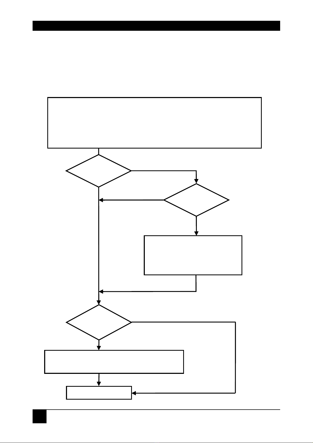
1. Quick Setup
This section briefly describes how to install your DDXI DVI/VGA KVM-Extender and
optimize the video signals. Unless you are an experienced user, we recommend that
you follow the full procedures described in the rest of this manual. Refer to the
command summary on page 10 when following this procedure.
Install system
1. Connect Remote unit to KVM.
2. Connect Local unit to CPU or switch.
3. Connect Local and Remote units with matching interconnection cable
(CATx, Multimode or Singlemode fiber).
4. Power up the system.
Carry out the Monitor Setup
procedure (please refer to its
manual and see page 36 in
this manual).
Carry out VGA Input Setup procedure
(please follow the instructions on page 38).
Done
Yes
No
Do you have a
DVI monitor?
Do you have a
DVI source?
Do you
have a flat screen
(TFT)?
No
No
Yes
Yes

QUICK SETUP
9
1.1 Video Input/Output
If possible, always use DVI output from your computer’s video card and DVI input to
a monitor. This provides the optimum video signal. If you use a VGA output from your
graphic source, the DVI-KVM Local unit must digitize the signal prior to transmission.
Similarly, if your remote TFT screen uses a VGA input, it must digitize the signal from
the Remote unit. In both cases, the built-in video processors must determine the
resolution and pixel phase for an optimized digitization. Your DVI Extender allows
you to optimize the video signal manually or automatically using its on-screen utility
(see Chapter 4). If you are using a VGA input to a TFT monitor, please follow the
manufacturer’s instructions.
You may have several possible options for video source output/monitor input. If this
is the case, for the optimum video quality, please select the highest ranked available
combination from the following table:
Video Quality Local Unit input Remote Unit output
1 DVI DVI
2 DVI VGA
3 VGA DVI
4 VGA VGA

DDXI DVI/VGA KVM EXTENDER FAMILY
10
1.2 Command Summary
The following table summarizes the ‘hot’ key command sequences used in system
configuration and video tuning on a Remote unit console.
Command
Keyboard
at Remote unit
Terminal or
Windows Utility program*
Enter OSD <Left Control>
+ <Left Shift> + <I>
<O> + <S> + <D>
+ <Enter>
Exit OSD <ESC> <X>
Select next
position <Right Arrow> <R>
Select previous
position <Left Arrow> <L>
Select Submenu <Enter> <S>
Select parameter
modification <Enter> <S>
Increase
parameter <Right Arrow> <R>
Decrease
parameter <Left Arrow> <L>
Accept and store
modified
parameter
<Enter> <S>
Back to the Menu
selection
* Commands are not case-sensitive.

OVERVIEW
11
2. Overview
2.1 Introduction
A basic KVM extension system comprises a Local unit (transmitter) and a Remote
unit (receiver). The Local unit connects directly to the computer (or a KVM switch
system) using the supplied cable(s). The user console (keyboard, mouse and
monitor) attaches to the Remote unit. The Remote and Local units communicate
video and data information along the interconnecting cable (see Figure 1). Local
units offer dual access, allowing the connection of a second user console close to the
computer. With the optional upgrade kit, you can also use DDXI DVI/VGA KVM
Extender units to communicate stereo audio and serial port signals.
DDXI DVI/VGA KVM Extender Series enables high-resolution video, PS/2 keyboard
and mouse signals to be communicated up to:
•300ft (100m) over Category 5, 5e, 6 or higher (CATx) cable.
•1200ft (400m) over Multimode fiber cable (50/125μ).
•600ft (200m) over Multimode fiber cable (62.5/125μ).
•6¼ miles (10km) over Singlemode fiber cable (9/125μ).
In a digital application (DVI input and output), there is no loss of picture quality
irrespective of extension distance and no adjustments are required. The DDXI
DVI/VGA KVM Extender Series also supports traditional analog VGA as well as
digital DVI. All combinations of DVI and VGA (graphics cards and monitors) are
supported, allowing equipment to be mixed. In a mixed analog/digital application,
some adjustment of the video signal is necessary to optimize the analog-digital signal
conversions. DDXI DVI/VGA KVM Extenders are equipped with various automatic
and manual video correction tools in an on screen utility (see page 25).
2.2 Glossary
The following terms are used in this guide:
CATx Any Category 5, 5e, 6 or higher cable.
Multimode Any multimode 2-fiber cable 50/125μ or 62.5/125μ
Singlemode Any singlemode 2-fiber cable 9/125μ
PSU The desktop power supply connected to the Local/Remote unit.
KVM Keyboard, Video and Mouse.
Console A keyboard, monitor, and mouse, plus optional serial/audio
devices.
Dual Access A system allowing connection of Local and Remote user
consoles.
Single Head An extender system that supports one monitor.
Dual Head An extender system that supports two monitors.

DDXI DVI/VGA KVM EXTENDER FAMILY
12
Figure 1 KVM extender system
Local Access
Dual Video Support
Serial/Audio and USB
extension options
KVM extension over CATx
or fiber optic cables.
LOCAL unit
REMOTE unit

OVERVIEW
13
2.3 Features
All members of the DDXI DVI/VGA KVM Extender Series offer the following features:
•Support for high video resolution over extended distances:
1600x1200@60Hz over all allowed distances - all lower resolutions with refresh
rates of at least 75Hz
•An optional available device with higher data transfer (2,5GBit/sec) allows a
resolution up to 1920x1200@60Hz
•All models come with dual access, to allow local or remote operation
(Local DVI access limited to screen resolutions up to 1280x1024).
•All control and video tuning carried out using an on screen display (OSD) with
settings stored in EEPROM memory.
•Local/Remote unit firmware and settings flash upgradeable.
•Intelligent PS/2 keyboard and mouse emulation ensures PCs do not lock-up and
allows peripherals to be hot-plugged.
•Transparent serial port (on certain models) enables any serial device to be
extended (up to 19.2K Baud). The serial port may be used to extend one device
(requiring handshaking lines), or up to three simple serial devices (no
handshaking).
•Bi-directional stereo audio (16-bit digitized) support on certain models enables
high-quality, low-noise audio extension.
•USB support on certain models; connect up to four USB devices directly to the
USB hub on the remote unit.
•Status indicator LEDs on each device.
•Small footprint chassis.
•Rack mount options available.
•CPU cables + Adapters included.

DDXI DVI/VGA KVM EXTENDER FAMILY
14
2.4 Product Range
There are eight products in the range and various upgrade kits:
DVI/VGA-only devices
K439-0W DVI Upgrade kit for additional video channel – CATx
(also as option for Dual Head)
K437-0W DVI Upgrade kit for additional video channel –
Multimode (also as option for Dual Head)
K438-0W DVI Upgrade kit for additional video channel –
Singlemode (also as option for Dual Head)
PS/2 Style Kits
K439-1W DVI-Extender Set: PS/2 Dual Access, CATx
K437-1W DVI-Extender Set: PS/2 Dual Access, Multimode
K438-1W DVI-Extender Set: PS/2 Dual Access, Singlemode
USB Style Kits
K442-2U DVI-Extender Set: USB Dual Access, Multimode
K442-2U DVI-Extender Set: USB Dual Access, Singlemode
Upgrade Kits
421-AU Audio/Serial Upgrade kit
421-TM PS/2-keyboard/mouse Upgrade kit for USB devices
437-25 2.5Gbit Upgrade for Multimode devices with a
resolution of 1920x1200 @60Hz
438-25 2.5Gbit Upgrade for Singlemode devices with a
resolution of 1920x1200 @60Hz
437 -G2 Double-width housing (for Dual Head or audio/serial
upgrades)

OVERVIEW
15
2.5 Compatibility
Interface Compatibility
•PS/2 Keyboard: Compatible with all standard keyboards. Certain keyboards
with enhanced features may also be supported with custom firmware.
•PS/2 Mouse: Compatible with all standard 2-button, 3-button and wheel mice.
•Audio: Input and output are line-level. Amplified speakers are required. A
microphone may be directly connected to the Remote unit (optional pre-
amplification).
•Serial: Transparent up to 19.2K Baud. The following serial signals are extended:
TX, RX, RTS, CTS, DTR, DSR. In rare cases, a wiring adaptor may be required
to transfer RI and DCD.
•USB: compatible to USB 1.0 and USB 1.1. Transmission fully transparent.
Some USB-CDROM or DVD burning devices may not work properly.
•Analog Video: VGA to UXGA. Separate sync, composite sync, or sync-on-
green. Maximum resolution and refresh rates depend on cable length and cable
type (see Appendix H: Specifications, page 42).
•Digital Video: DVI single link for resolution up to 1600x1200 at 60Hz. Frame
rates and colors depend on device type (CATx or Fiber – see Appendix D:
Video Modes and Frame Rates, page 49)

DDXI DVI/VGA KVM EXTENDER FAMILY
16
2.6 How to Use This Guide
This guide describes the installation and configuration of the DDXI DVI/VGA KVM
Extender Series. Although the connection and operation of the system is relatively
straightforward, you should consider the following before getting started:
Connection & Compatibility
If you have purchased an Extender Kit, this will contain all the cables required to
connect the Local unit to your PC or KVM switch. The Remote console (keyboard,
monitor and mouse) and any audio and serial equipment connect directly to the
Remote unit.
For information about connection and installation, see Installation, page 17.
Interconnection Cable
For DVI-KVM -CAT Extenders, you will need CATx (any category 5, 5e, 6 or higher)
cable, terminated with RJ45 plugs, to connect the Local and Remote units. Other
units require singlemode or multimode fibers (see Interconnection Cable
Requirements, page 18.
Adjusting Video
Due to the digital nature of the transmitted signals, there is no distortion of video
signals or skew problem even with CATx interconnection cables.
If you do not have a DVI source and a DVI monitor, you will need to adjust the
monitor and/or the Extender to the picture width and the pixel phase. You can do this
using the Auto Adjust or Manual Adjust procedures (see page 37).
•For experienced users there is a Quick Setup section at the start of this guide
(see page 8).
•For the full procedure, see Monitor Setup (page 36) and/or Extender Setup
(page 37).

INSTALLATION
17
3. Installation
For first-time users, we recommend that you carry out a test placement, confined to a
single room, before commencing full installation. This will allow you to identify and
solve any cabling problems, and experiment with the DDXI DVI/VGA KVM-Extender
more conveniently.
3.1 Package Contents
You should receive the following items in your extender package (all types):
•Extender Remote unit.
•6V DC 12W universal power supply for Remote unit.
•Extender Local unit.
•6V DC 12W universal power supply for Local unit.
•2x DVI-I to VGA adapter (DVI-I dual link male to HD15 female) connector.
•1x VGA to DVI-I adapter (HD15 male to DVI-I dual link female) connector.
•Programming cable (DB9 female to RJ11 4p4c).
•User manual.
•2x German-type power cord.
All DVI/VGA-only models are supplied with:
•DVI-I video (DVI-I dual link male-to-male) connector
All PS/2 models are supplied with:
•KVM CPU cable set (1.8m) with PS/2 (6-pin mini-DIN male-to-male) keyboard
and mouse connector and DVI-I video (DVI-I dual link male-to-male) connector
All USB types are supplied with:
•DVI-I video cable (DVI-I dual link male-to-male)
•USB cable (USB type A to type B)
•5V DC 12W universal power supply for Remote unit
(only required when connecting two or more High Power USB devices -
see Appendix E: USB – High Power/Low Power).
•1x German-type power cord (additional)
If anything is missing, please contact Technical Support (see Appendix G: Calling
Technical Support).

DDXI DVI/VGA KVM EXTENDER FAMILY
18
3.2 Interconnection Cable Requirements
To connect the Local and Remote units you will need:
•CATx Modules: S/UTP (CAT5) cable acc. to EIA/TIA 56A or TSB 36 or Digital
STP 17-03170. Four pairs AWG 24. Pinout acc. EIA/TIA 568A (10BaseT).
Screen must be connected on both ends. Please ensure that the connection is
tension-free.
•Fibre Cables:
Multimode: Two fibres 50μm or 62.5μm. E.g. I-V(ZN)H 2G50 (In
house patch cable)or I-V(ZN)HH 2G62,5 (In house Breakout cable) or
I/AD(ZN)H 4G50 (in house OR outdoor Breakout cable, stress
resistant) or A/DQ(ZN)B2Y 4G62,5 (outdoor cable, stress resistant
with protection against animal biting) All notations acc. VDE
specification.
Singlemode: Two fibres 9μm. E.g. I-V (ZN)H 2E9 (In house patch
cable) or I-V(ZN)HH 2E9 (In house Breakout cable) or I/AD(ZN)H 4E9
(in house OR outdoor Breakout cable, stress resistant) or
A/DQ(ZN)B2Y 4G9 (outdoor cable, stress resistant with protection
against animal biting) All notations acc. VDE specification.
A point to point connection is required. Having one or more patch
panels in the line is possible and allowed. Not allowed is a
connection from the fibre link interface to any other products,
especially telecommunications or network equipment.
•DVI, PS/2-Keyboard, PS/2-Mouse: Connect the supplied KVM CPU cable set
to your CPU (KVM.- Switch, etc.). Please ensure that the connection is tension-
free! Devices K455-1W + K455-2W
•DVI, USB-Keyboard, USB-Mouse: Connect the supplied KVM CPU cable set to
your CPU (KVM.- Switch, etc.). Please ensure that the connection is tension-
free! Devices K455-1U + K455-2U
•DVI: Connect the supplied DVI CPU cable set to your CPU (KVM - Switch, etc.).
Please ensure that the connection is tension-free! Devices K455-2W + K455-2U
•VGA Input: If you are using a VGA graphic source please use the delivered
DVI/VGA adapter.
•VGA Output: If you are using a VGA monitor please use the delivered VGA/DVI
adapter.
•Power Supply: Connect the supplied 6V/DC power supplies to the Plug
terminal on the rear of both Local and Remote units.
USB devices have an additional power supply. You need to attach this PSU to
the Remote unit if the total power consumption of the attached USB devices
exceeds 500mA (see Appendix E: USB – High Power/Low Power).

INSTALLATION
19
3.3 System Setup
To install your DDXI DVI/VGA KVM Extender system:
1. Switch off all devices.
2. Connect your keyboard, monitor(s) and mouse to the Remote unit as shown in
Figure 2 (K439-1W), Figure 4 (K437-1W/K438-1W) or Figure 6 (K442-2U/K443-
2U).
These ports may also be attached to the CPU side of a KVM
switch in order to have a Remote CPU. However, if you are
attempting to use the extender between cascaded KVM switches this
may not work. Please contact Technical Support to discuss your
application.
3. Connect the interconnect cable to the INTERCONNECT socket(s) as shown in
Figure 2 (K439-1W), Figure 4 (K437-1W/K438-1W) or Figure 6 (K442-2U/K443-
2U).
4. Connect the 6V power supply to power the unit.
Only use the power supply originally supplied with this
equipment or a manufacturer-approved replacement.
5. Using the supplied CPU KVM cable(s), connect the keyboard, monitor(s) and
mouse connectors on the computer (or KVM switch) to the corresponding
connectors on the Local unit as shown in Figure 3 (K439-1W), Figure 5 (K437-
1W/K438-1W) or Figure 7 (K442-2U/K443-2U).
Ensure that you attach the keyboard and mouse connectors to the correct ports.
The keyboard connector is purple; the mouse connector is green.
If your PC does not have a PS/2 mouse port, an active serial
converter will be required
6. For a dual access system, connect the keyboard, mouse and monitor for the
Local console to the appropriate ports on the Local unit. The ports may also be
used to feed into a KVM switch.
7. Connect the Interconnection cable from the Remote unit to the
INTERCONNECT socket on the Local unit as shown in Figure 3 (K439-1W),
Figure 5 (K437-1W/K438-1W) or Figure 7 (K442-2U/K443-2U).
8. Power up the system.

DDXI DVI/VGA KVM EXTENDER FAMILY
20
Figure 2 K439-1W Remote Unit
Figure 3 K439-1W Local Unit
DVI-I Connector – DVI and
VGA output – connect to
Remote console monitor
Connect to 6V
Power supply
Programming connector –
for firmware upgrades
Connect to PS/2 keyboard and
mouse using supplied cables
INTERCONNECT – carries video and
data signals – connect to Local unit
with CATx cable
INTERCONNECT – carries video
and data signals – connect to
Remote unit
Connect to Local
console keyboard
and mouse
Connect to CPU’s
keyboard and
mouse sockets
Connect to Local
console monitor
Connect to 6V
Power supply
Programming
connector – for
firmware upgrades
Connect to CPU
video card output
DVI-I Connectors
This manual suits for next models
7
Table of contents
Popular Extender manuals by other brands

Black Box
Black Box AC1081A instruction manual

AVLink
AVLink HDMI-RP user manual

Silvercrest
Silvercrest SWV 733 A2 Operating instructions and safety instructions

Wyrestorm
Wyrestorm EX-SW-0401-H2-PRO quick start guide

Black Box
Black Box ServSwitch Agility ACR1000A user manual

Vivo Link
Vivo Link VLHDMIEXT416 user manual


