Scarecrow SCARECROW 180 Operator's manual

USERS INSTRUCTION MANUAL
SCARECROW 180 ™
SCARECROW 360 ™
Scarecrow 180™ Scarecrow 360™

CONTENTS
Page 1 - Item Supplied and Available Acce orie
Page 2-3 - Practical Setup Tip
Page 4 - A embly / Fixing
Page 5-6 - Power Supply and Connection
Page 7 - Keypad Guide and Default Setting
Page 8 - Turning the Unit On/Off
Page 9-11 - Programming In truction
Page 11-12 - Other Feature
Page 13 - Pin Control / U e
Page 14 - Re-Set Default Factory Setting and Option Setting
Page 15 - Technical Support

ITEMS SUPPLIED
SCARECROW 180™
1 x fully automatic and random play bird dispersal unit, incorporating:
•10 standard distress calls.
•3 built in speakers,
•1 light sensor,
•Wall mounting bracket
•Keypad for setting controls.
1 x Po er Option; either 15V dc regulated s itch mode EU/UK po er supply, or Battery
Lead.
1 x U Clamp Pair; to mate ith built in brackets to provide pole mount option, and bolts etc.
SCARECROW 360™
1 x ‘slave’ unit to accompany the SCARECROW 180™
1 x Connection Cable; connection from 360 unit to 180 unit
SCARECROW 360™ SYSTEM
Complete 360° dispersal system comprising:
1 x SCARECROW 180™ fully automatic and random play bird dispersal unit (as above);
1 x Po er Option; either 15V dc regulated s itch mode EU/UK po er supply, or Battery Lead.
1 x U Clamp Pair; to mate ith built in brackets to provide pole mount option
1 x SCARECROW 360™ ‘slave’ unit to accompany the SCARECROW 180™
1 x Connection Cable; connection from 360 unit to 180 unit
ACCESORY ITEMS AVAILABLE
Solar Power Option
; suitable for B.I.R.D. System™, Scarecro 180™ and Scarecro
360™ System. System comprises:
•Solar Panel
•battery & regulator pack
•2m pole stand; as described belo
2m pole Non-piercing roof mount
; mounted on a 1m square base. This requires
the local purchase of four 450x450mm paving slabs, or equivalent, for stability.
1m pole Non-piercing roof Mount
; for use on flat or ridge style roof. This
requires the local purchase of four 450x450mm paving slabs, or equivalent, for stability.
Adaptor for non-piercing roof mount
; to ‘saddle’ a pitched roof peak.
Should any of the above accessories be required please contact your supplier, or Scarecrow direct, on
Page 1

PRACTICAL TIPS
Point of Broadca t
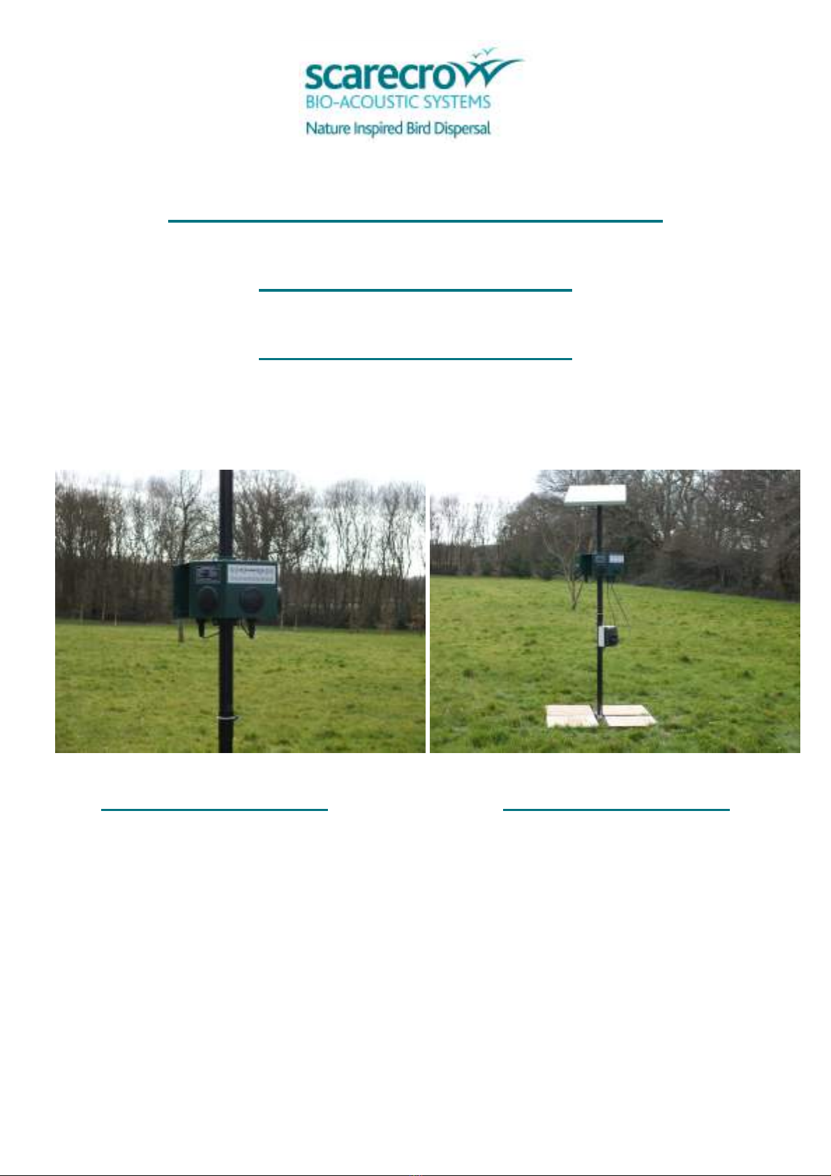
•Ideally, the point of broadcast should be from a high point – too lo to the ground ill
only limit the area covered, and therefore the success obtained.
Volume Level
•The volume of broadcast has to be at a natural level for the birds to identify the
broadcast as a natural call:
oToo loud - the broadcast ill merely appear to sound like a noise, and no
reaction is likely.
oToo quiet - they simply ill not hear the call, and again a dispersal reaction is
unlikely.
•To attain hat is perceived as a natural level for the target species, begin broadcasting
the system at the lo est volume level and then increase the volume until you see the
birds react to the call
Coverage
•The system is stated as providing coverage in each speaker direction to a distance of
100m.
•This is dependent on a number of factors such as the lie of the land, prevailing eather
conditions, strength/direction of ind, other ambient noise, air temperature and
obstructions to sound broadcast.
•As such, either a greater or lesser distance may be obtained.
•Taking this into account, it is important to remember that the broadcast needs to sound
at a natural level to the birds for greatest effect – too loud or too quiet, ill merely
either sound like a noise to the target birds and be ignored, or not heard at all.
Effect on other wildlife
•The calls broadcast are only recognisable by the target bird species, and therefore has
no lasting effect on other ildlife at all.
•That is not to say that there ill be no reaction – in some extreme cases, the broadcast
of a distress call may for example bring in a Ha k hoping to find some easy food.
Relocating the Scarecrow 180 / 360™
•One of the benefits of this system, if mounted on a pole/base unit, is that it can be
moved from location to location from time to time to enable different problem areas to
be tackled.
•Whilst this is an option, it is recommended that a system should ideally remain in situ if
an area is required to be kept free of birds.
•The concept of the system is to create the impression over time that the area is a
“threat area” and one therefore to avoid – so over time the bird numbers may even
reduce. This is achieved by the regular (but not too frequent) broadcast of the Distress
Call, hich clearly cannot be achieved if the system is relocated.
Page 2

PRACTICAL TIPS CONTINUED
•If it is decided to relocate the unit then this should not be too frequent – ideally no
more frequently than fortnightly. Having said that every location may be slightly
different, as are the reactions of different species on hearing their distress call, so it is
orth taking some time to observe ho the system orks best under your o n
circumstances.
Variable Volume
•The system incorporates a “variable volume” feature – during broadcast the volume ill
automatically vary bet een the maximum set level, and approximately 20 metres from
the unit.
•This is to provide the perception of predator movement, to aid to the overall confusion
and concern of the target specie, to improve dispersal performance.
•This feature also ensures that no matter here the target bird may be ithin the overall
coverage area during the time of broadcast, at some point the broadcast sound level
ill certainly sound as if it is at a natural level.
•This function can be disabled so the unit ill continually broadcast at the maximum set
level (please refer to page 14)
Independent Speaker Channel broadca t
•The system incorporates three independent speaker channels.
•The broadcast is made out of each channel in turn, independently, and on a randomised
basis.
•As ith the variable volume, this is to provide the perception of predator movement, to
aid to the overall confusion and concern of the target specie, to improve dispersal
performance.
•This feature orks in conjunction ith the variable volume.
Habitat Management
•Whilst the unique efficiency of SCARECROW bio-acoustic products is long established
SCARECROW GROUP LIMITED stress that they can only ork effectively as part of an
overall and planned programme of bird control.
•This ill include total hygiene management and here applicable the use of operatives
ho have been professionally trained.
•Without limitation, SCARECROW GROUP LIMITED ill not accept liability for any
consequences as a result of poor equipment maintenance, misuse, inappropriate use,
lack of operative training, failure of due diligence or through lack of prior project
consultation.
Page 3

ASSEMBLY / FIXING
•Both the Scarecro 180™ and the Scarecro 360™ are provided ith integrated
brackets at the back of the unit.
•For the Scarecro 180™ this is to facilitate either all or pole fixing.
•The Scarecro 360™ unit is fixed to the back of the Scarecro 180™, and designed to
provide full 360° broadcast by being fixed back to back and pole mounted – no U clamps
are required, but bolts are.
•If all fixing, bolts, nuts and ashers are supplied.
•If the Scarecro 180™ is to be pole mounted appropriate U clamps are provided for a
suitable standard type scaffold pole (pole not supplied).
WALL BRACKETS
U CLAMPS MOUNTED ON
POLE
Page 4

POWER SUPPLY AND CONNECTIONS
SCARECROW 180™
The standard Scarecro 180 requires just one cable connection, as supplied. One end of the
cable connection is fixed to the underside of the Scarecro 180, in the “Po er Input”
connection.
The other end is the choice made of either 15V DC regulated s itch mode EU/UK po er
supply, or Battery Lead, and is fixed to po er source.
SCARECROW 360™
When this additional unit is purchased to facilitate a full 360° broadcast, one further cable is
supplied for connecting the t o units – in both cases the connection is made by using the
“Master/Slave Connector” socket.
Page 5

SOLAR POWER OPTION
The solar po er unit is a standalone unit and has t o connectors.
The first is “Solar”, connecting the solar panel to the battery and regulator.
The second is “12V Out”, connecting the battery and regulator to the main Scarecro 180
unit, at “Po er Input”
Further instructions on the assembly of the Solar Pack and 2m stand are included ith these
accessories
Page 6

KEY PAD GUIDE AND DEFAULT SETTINGS
Standard Programmed Call :
1. Herring Gull 6. Pigeon
2. Black Headed Gull 7. Jackda
3. Starling 8. Canada Goose 1
4. Rook 9. Canada Goose 2
5. Cro 10. Birds of Prey
Standard Factory Setting :
•Unit volume is pre-set to cover a 50m distance
•Pin Disabled
•Light Sensor – Mid Point 5
•Random Broadcast Playback Timer set to Normal
When the unit is first provided from Scarecro , the system ill not have the PIN activated.
In this “unlocked state” all buttons on the keypad are operative.
Thereafter, if the User has activated the PIN, the system can be either be in a locked state or
unlocked hen first po ered up.
If locked, a PIN number is required to unlock the system and perform any functions.
Page 7

TURNING THE UNIT ON/OFF
Turn on the system.
•Press the ‘POWER’ button to s itch on.
•The red LED above the po er button ill turn on.
•If a PIN is enabled, LED’s 1-4 ill flash four times indicating that the system is locked.
•Enter the correct PIN number, if incorrect, the system ill shut do n immediately.
•The system ill also shut do n after 30 seconds if no PIN is entered.
Turn off system.
•Press and hold the po er button for 3 seconds until all number LED’s flash rapidly to
s itch off.
•If the system as in lo po er standby, the system ill po er up first, flash all number
LED’s rapidly then shut-do n hen the po er button is released.
•If a PIN is enabled, LED’s 1-4 ill flash indicating that the system is locked.
•Enter the correct PIN number, if PIN entered is correct, the system ill shut do n
immediately.
•The system ill remain on if the incorrect Pin as entered.
•If the system as in lo po er standby, the system ill po er up first, flash LED’s
1 – 4 to prompt for the PIN entry.
Lock the system.
•If PIN enabled and the system is unlocked, press the po er button briefly to lock the
system, all number LED’s ill flash and the system ill be locked.
Note:
The system ill lock itself after 15 minutes if no keys are pressed and the PIN is set and
enabled.
Unlock the system.
•Assuming the unit is on, press and hold ‘N’ for 3 seconds and LED’s 1-4 ill flash to
prompt PIN entry.
•Enter the correct PIN number hich ill be confirmed by all the number LED’s flashing
t ice. Incorrect pin ill be indicated by all number LED’s lighting for t o seconds.
Cancel IN entry mode.
•Briefly press the Po er button to exit PIN entry mode hile LED’s 1 – 4 are flashing.
Page 8

PROGRAMMING INSTRUCTIONS
Broadca t Random Timer
•The system has three main random timer functions that indicate ho long the interval
ill be bet een each call sequence broadcast. The System is automatically pre-set to
“Normal” mode – amend to “Severe” or “Re-Enforce” as required by pressing the
appropriate button briefly and LED comes on, and “Normal” LED goes out – function
mode amended.
•N = Normal = 20 to 45 minutes – This is the default setting and recommended everyday
setting
•R = Re-Enforce = 10 to 30 minutes – This setting should not be used for more than 48hrs
other ise the birds may habituate to the sound and make the system less effective
•S = Severe = 5 to 15 minutes - This setting should not be used for more than 48hrs
other ise the birds may habituate to the sound and make the system less effective
Bird Call
•Press 1-10 for the required Bird Calls.
•Press individual numbers one at a time and once the individual LED stays on, the call is
programmed.
•In the event the rong call is programmed, simply press the number again until the LED
goes off.
Volume
•The volume is set to 50m, as a factory setting default.
•Press either volume button, up or do n, to alter the volume/distance coverage as
required – very roughly, each number equates to about 10 metres.
•On pressing either volume button, the bird sequence ill start broadcasting
continuously in a “Test Mode” at the current set maximum level (i.e. the variable
volume feature ill not operate at this stage). This ill last for 10mins to enable you to
check the volume level is adequate for the required target area and then, after 10
minutes, automatically time out. If the process is completed sooner, press N, R or S as
appropriate, and the final volume setting made ill be the maximum level to hich the
system ill broadcast.
•While the volume key is pressed and for a fe seconds after, the number LED’s ill
sho the volume setting from 1 to 10.
•To override the 10 minute test mode and activate the random timer for broadcast, once
the volume is set at the correct level, re-press the required Broadcast Random Timer
Button e.g. N, R or S.
Page 9

PROGRAMMING INSTRUCTIONS CONTINUED
Light Sen or
•The light sensor tells the system to stop broadcasting at night to save po er and to
reduce noise nuisance.
•The DUSK timer runs for 1 hour at sunset to keep the system active after sunset to
discourage birds from roosting.
•The DAWN timer delays akeup of the system for 60 seconds to ensure that the system
is not triggered by passing motor vehicle headlights at night.
Light Sen or: Te t
•Briefly press one of the light sensor buttons to disable the da n / dusk timers.
•Cover the light sensor (positioned on left hand side of speaker belo keypad) ith hand
- the Amber LED should go out indicating the system is in night mode.
•Remove your hand and check the LED no goes to a solid Amber colour – this indicates
the system is no in day mode and the light sensor is orking correctly.
•During normal operation, the light sensor LED ill be on during daylight, it ill flash
hen da n or dusk timer is running and ill blink once every 5 seconds if in night mode
(to save po er).
Light Sen or: Adju tment
•Adjust Light Sensor by pressing the associated “up/do n” buttons repeatedly as
required; 1 = most sensitive to light, 10 = least sensitive.
•The light sensor level ill be sho n on the number LEDs hile operating the buttons
and for a fe seconds after release.
•Minimum setting disables the light sensor. This is achieved by adjusting the light sensor
do n until LED No 1 also goes out - this is confirmed by rapid flashing of all number
LED’s.
Light Sen or: Other
•Pressing the UP or DOWN buttons briefly ill bypass the da n and dusk timers hen in
"Da n/Dusk" Timer mode (e.g. amber LED is flashing). This allo s the system to go into
night mode immediately if dark, or day mode if daylight, ithout the delay.
Page 10

•During normal operation, the light sensor LED ill be on during daylight, it ill flash
hen da n or dusk timer is running and ill blink once every 5 seconds if in night mode
(to save po er).
Light Sen or: Typical Re ult
•The light sensor function enables the unit to be set up so it activates at da n and then
goes into night mode at dusk. Belo is an overvie of the basic results seen during
test on a partially cloudy day.
oLevel 0 = Disabled, unit al ays in day mode.
oLevel 1 = Unit deactivates 20 minutes after sunset
oLevel 2 = Units deactivates 15 minutes after sunset
oLevel 3 = Units deactivates 6 minutes after sunset
oLevel 4 = Units deactivates 2 minutes after sunset
oLevel 5 = Units deactivates 1 minute after sunset
oLevel 6 = Units deactivates at sunset
oLevel 7 = Units deactivates 1 minute before sunset
oLevel 8 = Units deactivates 2 minutes before sunset
oLevel 9 = Units deactivates 5 minutes before sunset
oLevel 10 = Units deactivates 6 minutes before sunset
Note: the system will continue broadcasting for a further 60 minutes after the times stated below, as the dusk
timer keeps the system active to prevent roosting.
Note: There is a slight delay before the sensor responds.
Note: If the light sensor is NOT enabled in the options function, all number LED’s will flash rapidly when either
button is pressed. It is enabled by default.
OTHER FEATURES
Low battery warning
•If the battery voltage falls belo 9v, the system ill shutdo n to prevent damage to the
battery.
•The next time the unit is po ered up (provided the battery remained connected) the
system ill flash code 5 and play “lo battery” through the speakers indicating that a
lo battery shutdo n had occurred.
•You must recharge the battery.
Page 11

Battery Con umption
Assuming 5 birds programmed on normal mode and volume set to mid output (8).Each bird
call ill play for an average of 80 seconds per speaker hich totals 20 minutes. The unit ill
be timing for an average of 30 minutes bet een broadcasts. (20 – 40 minutes for normal
mode)
Therefore the total dra in 24 hours ill = 1.632Ahr (1.63 Amp hours dra n per 24 hours)
Battery life expectancy assuming a fully charged battery:
6.5Ahr 6.5/ 1.63 = 4 days
40Ahr 40 / 1.63 = 24.5 days
72Ahr 72 / 1.63 = 44 days
80Ahr 80 / 1.63 = 49 days
Low Standby Mode
•The system ill go into a lo po er standby mode (if enabled) and no broadcast is
running.
•As standard each unit has lo po er standby mode activated.
•The system ill go into this mode if no buttons have been pressed for 15minutes, no
broadcast sequence is active during daylight and one hour after sunset has been
detected.
•A brief press of the po er button ill bring the system out of this mode.
•Lo standby mode is indicated by a brief flash of the light sensor LED during night time
or a brief flash of the set mode (N, R or S) during day time.
•To force lo po er standby to run, press ‘N’, ‘R’ or ‘S’ button to stop the current
broadcast then press po er button briefly, after 10 seconds the system should po er
do n into lo po er mode.
•Lo po er mode is indicated by a brief flash of the po er LED, the light sensor led (if
night) or either the ‘N’, ‘R’ or ‘S’ led’s if daytime.
LED meaning
•All number LED’s flash four times hen any button pressed = System locked by PIN,
press N for 3 seconds then enter PIN number.
•Number LED’s 1-4 flashing continuously = > PIN number entry expected.
•All number LED’s flash t ice after PIN entry = PIN number entry correct.
•All number LED’s on for 2 seconds = PIN number incorrect or timeout ERROR.
•All number LED’s scroll do n from 10 to 1 after factory reset = Confirmation of reset to
defaults.
•N,R or S LED flashing indicates that the random timer bet een broadcasts is running.
•A single number LED flashing indicates that particular bird is broadcasting.
Page 12

PIN CONTROL / USE
•PIN option factory setting is set to “Disabled” as default.
•Default PIN : 10, 10, 10, 10
Activate PIN Function and Save New Pin (u e when PIN Function not activated before)
•Press and Hold N for 3 seconds – Red LED’s 1- 4 ill no flash
•Enter the default PIN 10,10,10,10 – The N,R and S Green LED’s ill no flash
•Press S briefly and then enter ne 4 digit PIN t ice – All LED’s ill flash t ice to confirm
change. The PIN is no saved and enabled.
Di able PIN function
•Press and hold N for 3 seconds - Red LED’s 1- 4 ill no flash
•Enter the current user PIN or 10,10,10,10 if default - then press R to disable the PIN.
•The system ill no not require a PIN to operate.
Enable a previou ly di abled PIN
•Press and hold N for 3 seconds, enter the existing user PIN number
• Press N briefly. The system ill no require the user PIN to operate.
Note: After S, N or R has been pressed as above, the system reverts to normal operation
mode.
PIN number feature :
•If the system is locked by PIN, hold “N” for 3 seconds - LED’s 1-4 flash continually (these
LED’s flashing indicates “PIN entry mode”).
• If no PIN has been programmed yet, enter factory setting default PIN 10,10,10,10.
Other ise enter the saved PIN.
• LED’s 1-4 ill go out as you enter each digit.
• You should then see all LED’s flash t ice for confirmation of correct entry. System no
unlocked. (Wrong entry indicated by all lights lit for 2 seconds)
•If the PIN is active and after 15 minutes of no user input, the system ill revert to PIN
locked in hich case you ill have to press N for 3 seconds and then enter the PIN
number to unlock the system.
• If the PIN is entered incorrectly 5 times in a ro the buttons ill be locked out for 5
minutes before a retry is allo ed. All the number LEDs ill light for 2 seconds if N is
pressed for 3 seconds to try and enter a PIN number during lockout period.
• Briefly pressing the po er button ill lock the system if the PIN is enabled.
Page 13

RE-SET FACTORY SETTINGS
•If you have forgotten your PIN or ant to revert the unit back to its factory settings
please follo the belo steps:
•Press and hold N for 3 seconds until the 1- 4 Red LED’s flash enter PIN 4726
•You no have 15 seconds to complete the follo ing sequence
•Press S and hold until all LED’s flash t ice
•Press R and hold until all LED’s flash t ice
•Press N and hold until all LED’s flash t ice
•All number LED’s ill no scroll do n from 10-1 indicating the factory re-set and the
system ill s itch off.
•Please note the pin ill have no been re-set to the default 10,10,10,10
OPTION SETTINGS
Several of the features of the unit can be turned On/Off by follo ing the belo steps
To enter option setup mode, unlock system first if locked then press and hold ‘S’ for 3
seconds until all number LED’s scroll from 1 to 10;
•Use the number buttons to toggle the items listed belo .
•Press ‘POWER’ to save and quit.
•All the number LED’s ill scroll do n from 10 to 1;
Default
1. Auto timer enabled (on)
2. Enable light sensor (on)
3. Enable PIR and Remote start at night (off)
4. Enable lo po er standby mode (on)
5. Disable Variable Volume if set to on (off)
6.
7.
8.
9.
10. Test mode, short timings (off)
Page 14

TECHNICAL SUPPORT
Should you have any concerns about the installation or set up of your system, please
contact either the agent from hom the purchase as made, or Scarecro Bio-acoustic
Systems direct as follo s:
oPhone: 01825 766363
oEmail: support@scarecro .eu / sales@scarecro .eu
If an item needs to be returned to the manufacturer, the Returns Address is:
Scarecro Group Limited
The Old Dairy
Straight Half Mile
Maresfield
East Sussex
TN22 2HH
Page 15
This manual suits for next models
1
Table of contents
Popular Farm Equipment manuals by other brands

CIRTEX
CIRTEX T-RECS Installation guidelines

Teagle
Teagle Tomahawk 404M installation guide

Tatu Marchesan
Tatu Marchesan PST Plus instruction manual

Farmi Forest Corporation
Farmi Forest Corporation 90 OPERATION, MAINTENANCE AND SPARE PARTS MANUAL

Fransgard
Fransgard SV-250-09SE manual

IAE
IAE AG-fit Installation, operation & maintenance manual