SCE SCE-AC3400B460V User manual

Version No. 1-9 - 24.01.2022 Doc. No. 99571021201SG 1 / 17
Table of Content SCE-AC3400B460V
1. User manual 2 ..................................................................................................................................
2. Legal regulations 3 .........................................................................................................................
3. Safety instructions 4 ......................................................................................................................
4. Settings 5 .........................................................................................................................................
5. Functional principle 6 .....................................................................................................................
6. Technical data 7 ..............................................................................................................................
7. Mounting 8 .......................................................................................................................................
8. Mounting Principle 9 .......................................................................................................................
9. Electrical Connection 10 .................................................................................................................
10. Controller 11 ..................................................................................................................................
11. Wiring Diagram 14 ........................................................................................................................
12. Taking into Operation 15 .............................................................................................................
13. Trouble Shooting 16 .....................................................................................................................
14. Maintenance & Cleaning 16 .........................................................................................................
15. Transport & Storage 17 ................................................................................................................
16. Parts supplied / Spare parts / Accessories 17 ..........................................................................

Version No. 1-9 - 24.01.2022 Doc. No. 99571021201SG 2 / 17
1. User manual
This instruction manual contains information and instructions to enable the user to work safely, correctly and
economically on the unit. Understanding and adhering to the manual can help one:
Avoid any dangers.
Reduce repair costs and stoppages.
Extend and improve the reliability and working life of the unit.
PLEASE ENSURE TO USE THE RIGHT VERSION OF THE INSTRUCTION MANUAL SUITABLE FOR YOUR
UNIT.
Intended use
The unit is to be used exclusively for the dissipation of heat from control cabinets and enclosures (stationary,
not moving) in order to protect temperature sensitive components in an industrial environment. To meet the
conditions of use, all the information and instructions in the instruction manual must be adhered to.
General danger
Indicates compulsory safety regulations which are not covered by a specific
pictogram such as one of the following.
High electric voltage
Indicates electric shock danger.
Important safety instruction
Indicates instructions for safe maintenance and operation of the unit.
Attention
Indicates possible burns from hot components.
Attention
Indicates possible damage to the unit.
Instruction
Indicates possible danger to the environment.

Version No. 1-9 - 24.01.2022 Doc. No. 99571021201SG 3 / 17
2. Legal regulations
Liability
The information, data and instructions contained in this instruction manual are current at the time of going to
press. We reserve the right to make technical changes to the unit in the course of its development. Therefore,
no claims can be accepted for previously delivered units based on the information, diagrams or descriptions
contained in this manual. No liability can be accepted for damage and production caused by:
Disregarding the instruction manual
Operating error
Inappropriate work on or with the unit
The use of non-specified spare parts and accessories
Unauthorised modifications or changes to the unit by the user or his personnel
The supplier is only liable for errors and omissions as outlined in the guarantee conditions contained in the main
contractual agreement. Claims for damages on any grounds are excluded.

Version No. 1-9 - 24.01.2022 Doc. No. 99571021201SG 4 / 17
3. Safety instructions
Upon delivery the unit is already meeting current technical standards and can therefore be safely taken into
operation. Only authorised personnel is allowed to work on the unit. Unauthorised personnel must be prohibited
from working on the unit. Operating personnel must inform their superiors immediately of any malfunction of
the unit.
Please note that before starting to work on or with the unit, a procedure must be carried out inside the cabinet
on which the unit is to be mounted.
Before commencing work inside the cabinet, the control cabinet manufacturer's instruction must be read with
regards to:
Safety instructions.
Instructions on taking the cabinet out of operation.
Instructions on the prevention of unauthorised cabinet reconnection.
The electric equipment meets the valid safety regulations. One can find dangerous voltages (above 50 V AC or
above 100 V DC)
Behind the control cabinet doors.
On the power supply in the unit housing.
The unit has to be operated according to the type plate and the wiring diagram, and must be protected
externally from overloading and electrical faults via suitable protective devices.
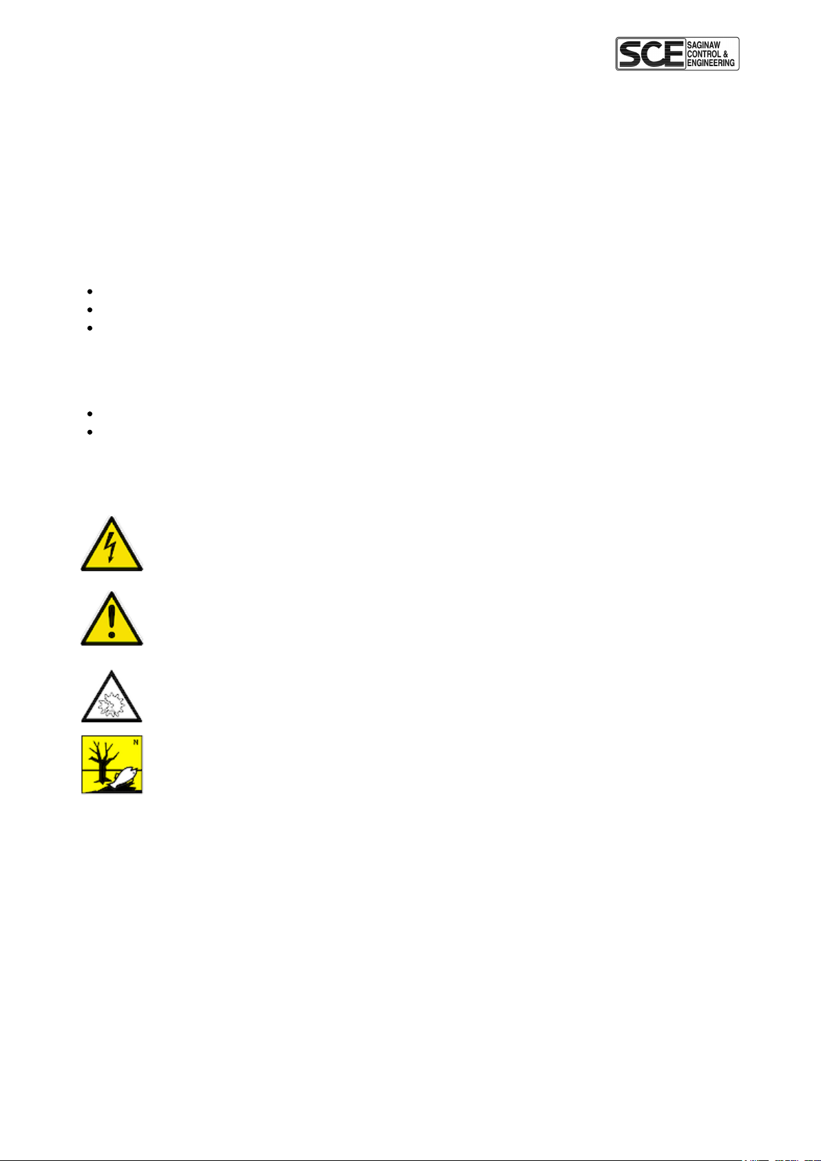
Danger through incorrect work on the unit
The unit can only be installed and maintained by technical competent and qualified
personnel, using only supplied material according to the supplied instructions.
Danger from electrical voltage
Only specialised personnel are allowed to maintain and clean the unit. The personnel must
ensure that for the duration of the maintenance and cleaning, the unit is disconnected from
the electrical supply.
Attention
Damage to the unit through the use of inappropriate cleaning materials. Please do not use
aggressive cleaning material.
Instruction
Damage to the environment through unauthorised disposal. All spare parts and associated
material must be disposed according to the environmental laws.

Version No. 1-9 - 24.01.2022 Doc. No. 99571021201SG 5 / 17
4. Settings
The cooling unit is intended to be used as a complementary accessory to larger industrial equipment. The unit
is used where heat needs to be dissipated from electrical control cabinets or similar enclosures in order to
protect heat sensitive components. It is not intended for household use.
The unit has two completely separate air circuits which ensure that the clean cabinet air does not come into
contact with the ambient air which may well be dirty or polluted.
Enclosure cooling units can dissipate large quantities of heat from sealed enclosures such as electrical
enclosures into the ambient air and at the same time reduce the cabinet internal temperature to below that of
the ambient air. The unit can function without problems in extreme ambient conditions (e.g. dusty and oily air)
with a standard operating temperature ranging between -40°C (-40°F) and +55°C (131°F).
Units can be ordered with an additional electrical cabinet heater. For the cooling capacities and evironmental
ratings please refer to the type plate data.

Version No. 1-9 - 24.01.2022 Doc. No. 99571021201SG 6 / 17
5. Functional principle
The cooling unit for enclosures works on the basis of a refrigeration circuit consisting of four main
components: compressor (1), evaporator (2), condenser (3) and expansion device (4).
The circuit is hermetically sealed and R134a refrigerant circulates inside it (R134a is chlorine free and has an
Ozone Destruction Potential [ODP] of 0 and a Global Warming Potential [GWP] of 1430). The compressor
compresses the refrigerant (thus taking it to high pressure and high temperature), and pushes it through the
condenser, where it is cooled by ambient air thus passing from the gas to the liquid state. At the liquid state it
then passes through the capillary pipe being a much lower pressure the refrigerant arrived to the evaporator
where it absorbs the necessary heat to change from liquid to gas state. The gas is then drawn back into the
compressor completing the cycle.
1. Air intake, cabinet side 7. Radial fan, ambient side
2. Radial fan, cabinet side 8. Condenser
3. Evaporator 9. Air outlet, ambient side
4. Air outlet, cabinet side 10. Filter dryer
5. Compressor 11. Capillary pipe
6. Air intake, ambient side

Version No. 1-9 - 24.01.2022 Doc. No. 99571021201SG 7 / 17
6. Technical data
Order Number SCE-AC3400B460V
Cooling capacity L35L35 3400 BTU
Cooling capacity L35L50 660 W @ 50 Hz
720 W @ 60 Hz
Enclosure heater 400 W
Compressor type Reciprocating compressor
Refrigerant / GWP R134a / 1430
Refrigerant Charge 210 g / 7.4 oz
High / low Pressure 445 / 88 psig
Operating Temperature Range -40°F - 131°F
Air flow volume (system / unimpeded) Ambient air circuit: 320 / 850 m³/h
Cabinet air circuit: 375 / 550 m³/h
Mounting Wall mounted
Housing Material Mild steel, powder coated
Dimensions A x B x C (D+E) 900 x 304 x 270 mm
Weight 87 lbs
Voltage / Frequency 400/460 V - 50/60 Hz 2~
UL Voltage / Frequency 400/460 V ~ 60 Hz 2~
Current L35L35 2.1 A @ 50 Hz
2.3 A @ 60 Hz
Starting current 9.2 A / 8 A
Max. current 2.5 A
Nominal power L35L35 770 W @ 50 Hz
830 W @ 60 Hz
Max. power 1,15 kW
Fuse (Do not use Class CC fuses) 5 A (T)
Short-circuit current rating 5 kA
Connection Connection terminal block
Ingress Protection IP 56 / Type 12, 3, 3R, 4
Approvals CE, cURus, cULus

Version No. 1-9 - 24.01.2022 Doc. No. 99571021201SG 8 / 17
7. Mounting
The power supply rating on unit rating plate must comply with mains rating.
Always disconnect the power supply before opening the unit.
The heat load to be dissipated from enclosure should not exceed specific cooling output of the unit at any
condition. At cooling unit selection always cater for a safety margin of at least 15% extra cooling output in the
worst conditions.
Ensure that flows of air leaving and entering the cooling unit, internal and external, are not obstructed. It must
also be ensured in accordance with UL, that the air outlet is not blowing air directly at an equipment
operator. Should this be the case a barrier or duct shall be provided to redirect the airflow.
Cooling unit enclosure air suction hole must be installed in the highest possible point. When installing the unit
on a door ensure it can take the weight.
Before drilling the enclosure ensure the fixing elements and couplings will not interfere with the equipment
inside the enclosure itself. Disconnect power before starting any work inside the enclosure. Following this 1:1
Scale Drilling Template drill the holes and make the required cuts on the enclosure. This template may have
been affected by storage conditions, please check this template by verifying values of the largest dimensions
before drilling. Fit the sealing strip on the cooling unit on the side connected to the enclosure and follow the
installation diagram.
This AC unit can only be mounted to a suitably Type rated enclosure to maintain it's Type rating. The Type and
IP rating of the enclosure should be the same or higher than that of the unit.

Version No. 1-9 - 24.01.2022 Doc. No. 99571021201SG 9 / 17
8. Mounting Principle
Do not use within the first 15 minutes after installation!
Use only the supplied mounting hardware
Tighten Screws to 4.5 Nm
Ensure the mounting surface does not warp after assembly and reinforce it if necessary
The bracket helps with the mounting of the cooling unit during installation
1 Screws
2 Toothed washers
3 Flat washers
4 Enclosure
5 Cooling unit
6 Mounting bracket

Version No. 1-9 - 24.01.2022 Doc. No. 99571021201SG 10 / 17
9. Electrical Connection
Door Switch
The unit can be switched on and of via a door contact switch. When delivered the door contact terminals are
bridged on the female connector. To connect the door contact switch remove the bridge and connect door
contact switch. The contact must be closed when the cabinet door is closed.
Alarm Contacts
Alarm contacts rated according to:
EN60730-1 8(4)A N.O., 6(4)A N.C., 2(2)A N.O./ N.C. @ 250Vac 100000 cycles
UL 873 8A resistive 2FLA 12LRA, pilot duty C300 @ 250Vac 30000 cycles
These contacts are not suitable for fluorescent loads (neon lights, etc.) that use starters (ballasts) with phase
shifting capacitors. Fluorescent lamps with electronic controllers or without phase shifting capacitors can be
used, depending on the operating limits specified for each type of relay.
SCCR
Refer to UL508A Supplement SB and Seifert Systems’ document Short Circuit Current Rating (SCCR) on methods
how to modify the available short circuit current within a circuit in the panel.

Version No. 1-9 - 24.01.2022 Doc. No. 99571021201SG 11 / 17
10. Controller
The display shows the temperature in the range of -50°C to +150°C (-58°F to +302°F). The temperature is
displayed with resolution of tenths between -19.9°C and +99.9°C (-3.8°F to +211.8°F). During programming, it
shows the codes and values of the parameters. The display also shows icons according to occurring events.
Display icons
Icon Function Description
1 Compressor relay active Flashes when activation is delayed or inhibited by
protection times, external disabling or other procedures
in progress
2 Alarm relay active
3 Heater relay active
4 Ambient blower relay active
Alarm Flashes when alarms are active
Heating mode Signals operation of unit in heating mode
Cooling mode Signals operation of unit in cooling mode
TEST Test mode in progress Activated only by manual procedure
Programming
The operating parameters can be modified using the front keypad. Access differs depending on the type of
parameter. Access to configuration parameters is protected by a password that prevents unwanted
modifications or access by unauthorised persons.
Setting cooling set point, St1:
1. Press “SET” and display should show St1 and then the pre-set value of St1. (default: +35°C / +95°F)
2. Reach the desired value by using ▲ or ▼.
3. Press “SET” again to save the new value of St1.

Version No. 1-9 - 24.01.2022 Doc. No. 99571021201SG 12 / 17
Setting heating set point, St2 (only for units supplied with internal heater):
1. Press “SET” twice slowly and display should show St2 and then the pre-set value of St2. (default: +5°C /
+41°F)
2. Reach the desired value by using ▲ or ▼.
3. Press “SET” again to save the new value of St2.
Setting temperature units (°C / °F), low temperature alarm and high temperature alarm:
1. Press “PRG” button for 5 seconds to reach the modifiable parameter list.
2. Use ▲ or ▼ to reach the desired parameter:
C18 for temperature unit of measure
°C = 0
°F = 1
P25 for low temperature alarm threshold (default -10°C / +14°F)
P26 for high temperature alarm threshold (default +55°C / +131°F)
3. Press “SET” on the desired parameter to display the current value.
4. Use ▲ or ▼ to reach the desired value.
5. Pressing “SET” temporarily saves the new value and returns to the parameters list.
6. Repeat steps 2-5 to set other parameters.
7. Press “PRG” for 5 seconds to permanently save the new values.
Set Point Paramter Default Range
Cooling St1 35°C / 95°F 20°C - 50°C / 68 -122°F
Heating (for units with heater) St2 5°C / 41°F -20°C - 20°C /-4°F - 68°F
Low Temperature Alarm P25 -10°C / 14°F -50°C - P26 / -58°F - P26
High Temperature Alarm P26 55°C / 131°F P25 - 150°C / P25 - 302°F
Test function
Different test functions can be used depending on the combination of keys pressed. Such tests run for the
duration of 4 minutes.
“SET+▲” tests Compressor and Ambient Blower relays.
“SET+▼” tests Alarms and Heater relays

Version No. 1-9 - 24.01.2022 Doc. No. 99571021201SG 13 / 17
Alarm Relay Operation
Both normally closed (NC) and normally open (NO) alarm contacts are provided. Under normal conditions, the
NC contact is closed and the NO contact is open. When an alarm condition is present, the NC contact will open
and the NO contact will close.
State Alarm relay Display
1 System powered OFF
2 System powered ON
- NO ALARM
- Door Contact Closed
3 System powered ON
- Door Contact Open
4 System powered ON
- ALARM STATE
Notes:
State 2: Additional icons (1,3,4, Reverse, Direct, Test) depending on operation.
State 3: The display shows “OFF” alternating with the standard display.
State 4: The display shows “EXX” alternating with the standard display – at the same time, the alarm icon
flashes.
Typical alarm codes:
Error Code Description
E01 Probe B1 fault
E02 Probe B2 fault
E04 High temperature alarm
E05 Low temperature alarm
Important Notes
Whilst programming, if no button is pressed for 10 seconds, the display starts flashing, and after 1 minute
returns to the main display without saving changes.
To increase scrolling speed, press and hold the ▲ or ▼ button for at least 5 seconds.
When pressing “PRG” for 3 seconds, the firmware revision code is displayed for 2 seconds.
When cleaning the controller panel, do not use ethanol, hydrocarbons, ammonia or their by-products.
Use neutral detergents and water.
In order to protect the unit’s components, minimum relay output on (3 or 7 minutes) and off (4 minutes)
times and minimum time (7 or 11 minutes) between activation of the same relay output are applied.
In case of digital inputs not configured, probes not fitted or configured, or St2 not enabled on the
controller the display shows ‘nO’.

Version No. 1-9 - 24.01.2022 Doc. No. 99571021201SG 14 / 17
11. Wiring Diagram
1 L1
2 LX
3 L2
4 PE
5 Alarm (NO) P1
6 Alarm (COM) P2
7 Alarm (NC) P3
8 Door Contact T1
9 Door Contact T2

Version No. 1-9 - 24.01.2022 Doc. No. 99571021201SG 15 / 17
12. Taking into Operation
Attention! The unit can be damaged by lack of lubricant. To ensure that the compressor is adequately
lubricated the oil, which has been displaced during transport, must be allowed to flow back into it. The unit must
therefore be allowed to stand for at least 30 min. before being connected to the mains and taken into
operation. The unit / system must be protected with a MCB Type D or K.
Upon connection the internal fan will start working. If the temperature inside the enclosure is higher than the
set value of the controller both the compressor and external air fan start working. Once the air inside the
enclosure reaches the set temperature the compressor and external fan will stop.
The hysteresis is 3K, the minimum ON-time is 4 minutes, the minimum OFF-time is 3 minutes, for units with a
cooling capacity of more than 1 kW is it usually 7 minutes.
The unit is pre-set at 35°C, which is suitable for most of the electronic devices.

Version No. 1-9 - 24.01.2022 Doc. No. 99571021201SG 16 / 17
13. Trouble Shooting
Failure Condition Cause Solution
Unit
doesn't
cool
Internal fan does not work Power not connected. Verify power supply
Internal fan works, external fan
and compressor don't work
Enclosure temperature is below
setting temperature (St)
Verify values of parameter
"St"
Door switch contact is open Verify door switch
Controller doesn't work Replace controller
Internal fan works, external fan
and compressor don't work.
Display shows alternating OFF
and temperature
The sequence of the phases
inside the power supply
connector is incorrect
Change phases inside power
supply connector
Unit
doesn't
cool
External and internal fan work,
compressor does not work
Compressor motor electrical
failure
Have compressor replaced
by qualified service technician
Capacitor for compressor failed Replace capacitor
Compressor works, external fan
doesn't work
External fan needs to be
replaced Replace external fan
Enclosure
temperature
too hot
Compressor and fans (external
and internal) work all the time Cooling unit undersized Enclosure needs a cooling
unit with with higher capacity
Compressor and external fan
work in alternating mode
(ON / OFF)
Thermal compressor protector
triggered
Verify if ambient temperature
is too high,clean condenser
Refrigerant leakage Contact dealer/service center
Excessive
condensate
Enclosure door open Ambient air gets into the
enclosure
Ensure door is closed, add
a door switch and connect
it to controller
Enclosure door closed
Enclosure IP protection class
is below IP54
Seal all openings of the
enclosure
Damaged or misplaced sealing
strip
Repair sealing strip
accordingly
14. Maintenance & Cleaning
Always switch power supply off before starting any maintenance on the unit.
The cooling unit is generally maintenance free and can be operated without filters in most environments. For
units with filters these should be checked, cleaned and if necessary replaced on a regular basis. In addition the
unit should have regular functional tests (approx. every 2,000 hours depending on the grade of ambient
pollution).
Disposal.
The cooling unit contains R134a refrigerant and small quantities of lubricating oil. Replacement, repairs and
final disposal must be done according to the regulations of each country for these substances.

Version No. 1-9 - 24.01.2022 Doc. No. 99571021201SG 17 / 17
15. Transport & Storage
Malfunction due to transport damage
On delivery the carton box containing the unit must be examined for signs of transport damage. Any transport
damage to the carton box could indicate that the unit itself has been damaged in transit which in the worst case
could mean that the unit will not function.
The unit can only be stored in locations which meet the following conditions:
temperature range: - 40°C to + 70°C
Relative humidity (at 25°C): max. 95 %
Returning the unit
To avoid transport damage the unit should be returned in the original packing or in a packing case and must be
strapped to a pallet. If the unit cannot be returned in the original packing please ensure that:
A space of at least 30 mm. must be maintained at all points between the unit and the external packing.
The unit must be shipped in the same position as it was mounted.
The unit must be protected by shock resistant padding (hard foam corner pieces, strips or cardboard
corner pieces)
16. Parts supplied / Spare parts / Accessories
1 x Cooling unit with individual packaging
1 x Plastic bag containing:
- Instruction manual with technical information
- CE Conformity Declaration
- Drilling template in 1:1 scale, including general information about the unit
1 x Installation pack containing:
8 x M6 Bolts
8 x A6.4 Toothed Washers
8 x A6.4 Washers
1 x Female connector with shorted wired positions for door contact
Saginaw Control and Engineering
95 Midland Road
Saginaw, MI 48638
Phone: 989 / 799-6871
Fax: 989 / 799-4524
Table of contents
Other SCE Accessories manuals
Popular Accessories manuals by other brands

Roos
Roos ELRO manual

Leuze electronic
Leuze electronic PRK3CLA Autokollimation manual

Awntech
Awntech BAHAMA Owner's Manual & Installation Instructions

ICARO paragliders
ICARO paragliders XEMA 2 manual

Notifier
Notifier FST-751 Installation and maintenance instructions

Cooper Controls
Cooper Controls Greengate OEC-U-AF Series installation instructions