Schaefer IT 1686.4 Instruction manual

77855 Achern-Gamshurst
Oststrasse 17 Germany
Tel. : (49) 78 41 / 20 52- 0 No. 70.IT1686.4 E
Fax : (49) 78 41 / 20 52-52 Rev. A Page 1/3
AC / AC Inverter
IT 1686.4
Documentation:
Page:
Specifications 2
General description 3
Safety and General Instructions 77 SI01 E
Connection diagram 73 IT1686.4 E
Dimensions outline drawing 74 16530IT E
Documentation Date Signature
Issued 13.03.2014 A. Scherer
A General description, add. Safety and General Instructions 77 SI01 E
0 First edition 07.12.2004 M. Rohrbeck
Rev. Description Date Signature

77855 Achern-Gamshurst
Oststrasse 17 Germany
Tel. : (49) 78 41 / 20 52- 0 No. 70.IT1686.4 E
Fax : (49) 78 41 / 20 52-52 Rev. A Page 2/3
Specifications IT 1686.4
Input
Voltage range
Frequency
Recommended input fuse
No-Load input power
Hold-up time
Immunity:
- ESD
- Fast transients
- Surges
220 ... 240V AC -15/+10%, unit switches off at under- and overvoltage
50 / 60Hz
6A slow, external
approx. 20W
10 ms. typical
acc. to EN 61000-4-2 (level 3)
acc. to EN 61000-4-4 (level 3)
acc. to EN 61000-4-5 (level 3)
Output
Waveform
Voltage and current rating
Power rating
Line regulation
Load regulation (10-90%)
Frequency
Efficiency at full load
Distortion
Overload protection
Surge power
Short circuit current
Crest factor
Turn-on rise time
Power factor
sinewave
115V AC
500VA
2 %
3 % typical, 4 % max.
400 Hz, crystal stabilized
85 % typical
5 % typical
current limited to approx. 1.05 I
nom
2 x P
nom
for 1 sec.
electronically limited to 3 x I
nom
approx. 3
Softstart, 100ms typical
cos
n
$
0.7 inductive / capacitive
General
Temperature coefficient
Operating temperature
Load derating
Storage temperature
Cooling
Switching frequency
Isolation resistance
Isolation test
Safety / Construction
Earth leakage
RFI-interference
Connection
Mounting instructions
0.05 %/°C typical
-20°C to +75°C
2.5 %/°C from +55°C
-40°C to +85°C
natural convection
approx. 20 kHz
> 10 M
S
at 500V DC
acc. to EN 60950-1: 2003
< 3.5 mA at 230V AC, acc. to EN 60950
acc. to EN 55022, class A
see connection diagram
cooling fins to be vertically arranged /
above and below of inverter at least 40 mm distance to neighboring parts.

77855 Achern-Gamshurst
Oststrasse 17 Germany
Tel. : (49) 78 41 / 20 52- 0 No. 70.IT1686.4 E
Fax : (49) 78 41 / 20 52-52 Rev. A Page 3/3
General Description Inverter
The figure beside shows the connection of a switchmode inverter and a transformer.
The figure below shows the circuit of the inverter:
The intermediate circuit voltage (DC-input voltage) is transformed by the power transistors T1-T4
with the parallel inverse diodes D1-D4 in a pulse-width square-wave voltage. The choke with the
windings LI and LII integrates this voltage, and at the capacitor C there is a sinusoidal output voltage.
The power transistors are controlled by opto-coupler, making sure, that not both transistors of one
branch are switched on at the same time by the control pulses. The output voltage is connected via
sense leads to the control circuit and controls after a comparison with a reference the control pulses
for the power transistors.
The output signal of the current transducer is also supplied to the control circuit and serves for current
limiting.
Alternating voltage at the output of the inverter is transformed by means of a transformer to the
requested output voltage with galvanical isolation.

Safety and General Instructions
77855 Achern-Gamshurst Tel.: +49 7841/2052-0 No.: 77 SI01 E
Oststrasse 17 Germany Fax: +49 7841/2052-52 Rev. A Page
1
of
2
The following general safety precautions must be observed during all phases of operation of the power supply. Failure to comply
with these precautions or with specific warnings elsewhere in this manual violates safety standards of design, manufacture, and
intended use of the unit. Schäfer Elektronik GmbH assumes no liability for the customer’s failure to comply with these
requirements.
GENERAL
This product is a Safety Class 1 unit (provided with a protective earth terminal). The protective features of this product may be
impaired if it is used in a manner not specified in the operating instructions.
Installation and service work must be performed only by qualified personnel who are familiar with the associated risk.
Operation of the power supply produces dangerous internal voltages. The instructions VDE 0100, 0105, 068 (T2 §5) have to be
strictly observed.
ENVIRONMENTAL CONDITIONS
The unit should only be used for its determinate purpose. The power supply is intended for indoor use in overvoltage category II,
pollution degree 2 environments, according to EN 60950. To comply with other requirements of EN 60950 in regard to stability
(mechanical and thermal), fire hazard, injury, etc., the equipment must be installed in an enclosure or cabinet.
It is designed to operate at a maximum relative humidity of 95% and at altitudes of up to 2000 meters.
Do not operate in an explosive atmosphere.
Do not operate the unit in the presence of flammable gases or fumes.
BEFORE APPLYING POWER
Establish that the input lines are voltage free before attempting to connect them. Establish that the manner of installation is in
accordance with applicable electrical regulations, before proceeding with any electrical work.
Verify that the product is set to match the available line voltage, the correct fuse is installed, and all safety precautions are taken.
Do not exceed input and output ratings. Note also the level of signal- and control cables
GROUNDING
To minimize shock hazard, the chassis and cabinet must be connected to an electrical ground (PE). For power supplies designed
to be hard-wired to the ac power lines (mains supply), connect the protective earth terminal to a protective conductor before any
other connection is made. Any interruption of the protective (grounding) conductor or disconnection of the protective earth
terminal will cause a potential shock hazard that could result in personal injury.
FUSES
Only fuses with the required rated current, voltage, and specified type (normal blow, time delay, etc.) should be used. Do not use
repaired fuses or short-circuited fuse holders. To do so could cause a shock or fire hazard.
DO NOT SERVICE OR ADJUST ALONE
Do not attempt internal service or adjustment unless another person, capable of rendering first aid and resuscitation, is present.
DO NOT SUBSTITUTE PARTS OR MODIFY INSTRUMENT
Because of the danger of introducing additional hazards, do not install substitute parts or perform any unauthorized
modifications to the power supply . Return the unit to Schäfer Elektronik GmbH for service and repair to ensure that safety
features are maintained. To avoid the risk of electrical shock, always disconnect the input voltage, any external power source and
wait until the internal capacitors are discharged, before disconnecting the device
Units that appear damaged or defective should be made inoperative and secured against unintended operation until they can be
repaired by qualified service personnel.

Safety and General Instructions
77855 Achern-Gamshurst Tel.: +49 7841/2052-0 No.: 77 SI01 E
Oststrasse 17 Germany Fax: +49 7841/2052-52 Rev. A Page
2
of
2
AIR FLOW
It is preferable that the airflow to the power supply is filtered and below 55°C. An airflow
resistivity (pressure drop) of below 20 kPa is required to comply with EN60950 pollution category
II. Diffused thermal energy is required to be exhausted and replaced by air as detailed above.
Thermal management is required where the air provided to a power
supply complies with the power supply’s design parameters. The use of fans requires an
increase in airflow to a minimum rate of 120m³/h (corresponding to 70 cfm). The airflow
resistivity and respective pressure drop should be considered when a fan is required.
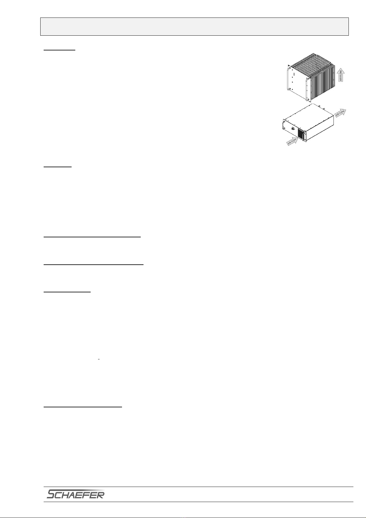
DIRECTION OF AIR FLOW
Typically, Schaefer modules and systems are cooled through air supply entering from
below and exiting above, with the exception of models of series C/B 5100, 5200, 5300,
5400, 6400 and 6600 whose airflow is from front to back. Custom designs also offer
lateral cooling. Such details however, are project specific
.
CABINET
A cabinet may be employed to enhance a module / system,.
•This may be required to fulfill the increased IP / NEMA rating, due to a negative effect of the solution on the
environment.
•Specifically, with unclean, saturated, corrosive or otherwise aggressive air quality it may be required to employ a
cabinet with a combination of features such as hermetical sealing and air exchange amongst others.
•The enclosure must be capable of sustaining the weight of the modules, specifically if module support rails are used.
•Stationary cabinets should be fastened to the ground.
•The center of gravity must be as low as possible with portable systems.
TRANSPORTATION OF MODULE
The grips on the front of the modules are to assist in module insertion into a sub-rack, and not for supporting the weight of the
module.
WALL MOUNT / CHASSIS MOUNT
Modules with a mounting plate or angle are designed for integration into the host equipment. They are not for employment
outside of an enclosure.
MAINTENANCE
Check the applied voltages and screw connections at periodic intervals in order to recognize any irregularities in the performance
of the power supply. If necessary, correct through adjustments and calibration.
Clean the power supply at certain intervals from dirt and dust which may have accumulated.
Record technical, operational and environmental data, that is to be used as a reference for evaluation.
Due to storage conditions, the following maintenance may be necessary:
a. A reforming procedure has to be done after 3 years of voltage-free storage under normal temperatures (+5° …+35°C)
b. A reforming procedure has to be done after 1 year of voltage-free storage under extended temperatures
(-40° ...+5°C and +35° ... +85°C).
Reforming procedure:
Due to increased leakage current of the internal electrolytic capacitors after voltage-free storage, the capacitors have
to be reformed. For this purpose, the rated input voltage has to be applied to the terminals.
Leave the input voltage applied for a period of 1 hour. Subsequently, the unit is stored under no voltage conditions for 12 to
48 hours at a temperature between 15°C and 35°C.
Afterwards the capacitors are reformed and meet the specified values.
STORAGE INSTRUCTIONS
Storage temperature: -40°C ... +85°C
We recommended the following conditions for storage:
- Do not store the unit at a high temperature ( at higher temperatures the ageing process is increased ) or in high humidity.
Store the unit indoors at a temperature of +5 …+35°C and a humidity of less than 75% RH.
- Keep the unit in the original package.
If the units are stored below the operating temperature, then they have to be left for at least 5 hours at operating temperature
conditions to ensure there is no condensing water present before operation.

77855 Achern-Gamshurst
Oststrasse 17 Germany
Tel.
Fax
: (49) 78 41 / 20 52- 0
: (49) 78 41 / 20 52-52
No.
Rev.
73.IT 1686.4 E
0 Page 1/1
Connection Diagram IT 1686.4
applies to:
- AC input
- AC output
The pins of the connector are rated 15 A max. At higher
currents pins internally parallel connected must also be
paralleled externally at the mating connector.
Rear view
Connector F24+H7 DIN 41612
Rear view
Connector H15 DIN 41612

Table of contents
Other Schaefer Inverter manuals
Popular Inverter manuals by other brands

RENON
RENON Xtreme LV Series user manual

ABB
ABB ACS880-07CLC Hardware manual

Immergas
Immergas 3.025469 Instruction booklet and warning

Agilent Technologies
Agilent Technologies U9391C Operating and service manual

Santerno
Santerno Sinus Penta Assembly instructions

MULTIQUIP
MULTIQUIP M1870400004 Operation manual