Schaeffler EWELLIX LIFTKIT-OM User manual

CATEGORY
MAX 2 LINES
INSTALLATION, OPERATION AND
MAINTENANCE MANUAL
LIFTKIT-OM

2
LIFTKIT-OM
2
Contents
WARNING
Please read this manual before installing, operating or
maintaining this lifting column. Failure to follow safety
precautions and instructions could cause lifting column failure
and result in serious injury, death or property damage.
Keep this manual nearby for future reference.
1.0 General information......................................................3
1.1 Information in this manual ...............................................3
1.2 Explanation of symbols and signal words ......................3
1.3 LIFTKIT designations ......................................................4
1.4 Related documents .........................................................4
1.5 Target audience...............................................................4
2.0 Safety .............................................................................5
2.1 Intended use....................................................................5
2.2 Safety elements ..............................................................5
2.3 Application notes ............................................................5
2.4 Potential risks ..................................................................5
2.5 E-Stop setup and behavior .............................................5
3.0 LIFTKIT components....................................................6
3.1 Scope of delivery.............................................................6
4.0 Mechanical installation................................................7
4.1 Tools required..................................................................7
4.2 LIFTKIT mechanical setup ..............................................7
5.0 Initialization of LIFTKIT and robot installation .........8
6.0 Hardware connection SBOX .......................................9
6.1 Hardware connection SBOX ...........................................9
6.2 Safety connection ...........................................................9
6.3 LIFTKIT connection setup............................................. 10
7.0 Software instruction for Ewellix LIFTKIT
Component for TMow ..................................................... 11
7.1 Introduction.................................................................... 11
7.2 Installation ..................................................................... 11
7.3 Command Component.................................................. 14
7.4 Error Codes ...................................................................20
7.5 Software update SBOX .................................................21
7.6 SBOX IP address setting...............................................22
8.0 Specications .............................................................24

33
1.0 General information
DANGER
Indicates a dangerous situation, which
will lead to death or serious personal
injury, if the precautionary measures are
ignored.
WARNING
Indicates a dangerous situation, which
can lead to minor or moderate injury or
property damage, if the precautionary
measures are ignored.
CAUTION
Indicates a dangerous situation, which
can lead to minor or moderate injury
the precautionary measures are ignored.
NOTICE
Indicates information considered
important, but not hazard-related (e.g.
messages relating to property damage).
NOTE
Emphasizes useful hints and
recommendations as well as information
for ecient and trouble-free operation.
1.1 Information in this
manual
This manual provides important information on how to work
with the actuator (also called device or drive) safely and
eciently.
The manual is part of the device, must always be kept in the
device’s direct proximity and should be available for person-
nel to read at any time . All personnel working with the de-
vice must read and understand this manual before starting
any work. Strict compliance with all specied safety notes
and instructions is a basic requirement for safety at work.
Moreover, the accident prevention guidelines and general
safety regulations applicable at the place of use of the de-
vice must also be complied with.
For a better representation of the circumstance of use, the
illustrations used are not necessarily to scale and may vary
from the actual design of the device.
1.2 Explanation of symbols
and signal words
Safety precautions
Safety precautions are identied by symbols and signal
words as shown to the right . The signal words indicate the
severity of the hazard and the chance it could occur.
Follow these safety precautions and act cautiously in order
to avoid accidents, personal injury and damage to property.
These installation instructions describe the setup and opera-
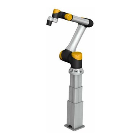
tion of LIFTKIT, a vertical lifting axis for collaborative robots.
Warning label
The box contains hazardous voltage. Disconnect the power
before opening the box.
Do not touch or change any wiring inside the box, except it
is stated in this manual.

4
LIFTKIT-OM
4
1.3 LIFTKIT designations
LIFTKIT contains a lifting column, a controller and additional
accessories enabling easy integration with a collaborative
robot. Depending on LIFTKIT typekey chosen, dierent con-
gurations of these included products are possible.
1.4 Related documents
This instruction manual does not replace the operating ma-
nuals of the included products, but adds additional instruc-
tions relevant to the setup and operation of the LIFTKIT's
system related to collaborative robots.
For general information and safety instructions please refer
to installation, operation and maintenance manuals available
at www.ewellix.com.
• TC-08023-EN-May 2020 THG-TLG-TLT operating manual
• TC-08005-EN-March 2020 SCU operating manual
1.5 Target audience
This manual is intended for qualied technical personnel
who install and use LIFTKIT in their application. This manual
and the corresponding operating manuals should be kept
available for reference at all times.
Qualied personnel is able to carry out assigned work and
to recognize and prevent possible dangers self-reliantly due
to its professional training, knowledge and experience as
well as profound knowledge of applicable regulations.
Ordering key L I F T K I T - - - 0 0 -
Robot
OM Omron
Stroke
stroke retracted length extended length
500 500 mm 525 mm 1 025 mm
600 600 mm 575 mm 1 175 mm
700 700 mm 625 mm 1 325 mm
800 800 mm 675 mm 1 475 mm
900 900 mm 725 mm 1 625 mm
A00 1 000 mm 775 mm 1 775 mm
B00 1 100 mm 825 mm 1 925 mm
C00 1 200 mm 875 mm 2 075 mm
D00 1 300 mm 925 mm 2 225 mm
E00 1 400 mm 975 mm 2 375 mm
Electrical options
11 120 V AC / US cable
22 230 V AC / EU cable
23 230 V AC / CN cable
24 230 V AC / UK cable
25 230 V AC / CH cable
Column type
601 TLT

55
2.0 Safety
2.0 Safety
This section provides safety aspects supplementary to the
safety aspects described in the relevant operating manuals
of the included devices. Failure to comply with the guide-
lines and safety instructions contained in this manual may
result in serious hazards that could cause possible serious
injury or death, or damage to the device or equipment.
The listed safety aspects must be reviewed and taken into
account in the nal application risk assessment prior to the
use of LIFTKIT.
2.1 Intended use
LIFTKIT has been designed and built for the intended use as
described in the operating manual of the column, with addi-
tional intended use dened as
• Lifting of a robot to extend its operating range.
Any use that extends beyond the intended use or a use dif-
ferent than the one described above is deemed misuse.
Any type of claims resulting from damage caused by misuse
are excluded.
2.2 Safety elements
The LIFTKIT has a range of safety elements built in to allow
its integration into a robot application, including safety relay
certied according ISO 13849-1, allowing STO up to PLe,
Cat. 4
2.3 Application notes
• Integration with an emergency-stop is required for its in-
tended use.
• Install emergency stop functions for the column and inte-
grate them into the safety chain of the complete system
prior to operating LIFTKIT.
• The emergency stop function has to be connected in such
a way that a disruption of the power supply or the activa-
tion of the power supply after a power disruption cannot
cause a hazardous situation for persons and objects.
• The emergency-stop systems must always be freely ac-
cessible.
2.4 Potential risks
The following risks during LIFTKIT operation have to be con-
sidered in an application specic risk assessment
• The column does not detect an impact automatically and
does not stop movement upon impact. This can lead to:
-Crushing of a person or an object in the path of the col-
umn, causing serious injury or death or property
damage.
-Dynamic impact to a person or an object causing serious
injury or death or property damage.
• It is possible that the column movement does not stop at
the desired position
-Movement of the robot can occur at a dierent position
than intended, causing signicant serious injury or death
or property damage.
2.5 E-Stop setup and
behavior
The LIFTKIT has two e-stop mechanisms. One is integrated
into the SBOX, the other directly into the SCU. The SCU
mechanism is software controlled and is much faster, but
only the SBOX mechanism guarantees an STO up to PLe,
Cat.4. It is recommended to integrate both mechanism into
the safety system. See the following table for comparison:
E-Stop
mechanism
Performance level
ISO 13489 -1
Stop distance Stop time
SCU Not rated 18 mm 200 ms
SBOX Up to PLe, Cat. 4 28 mm 750 ms
6
LIFTKIT-OM
6
3.0 LIFTKIT components
Screws for
mounting plates
Omron attachment plate Bottom mounting plate
3.1 Scope of delivery
The following enumerated parts are delivered and are de-
picted in Fig 1.
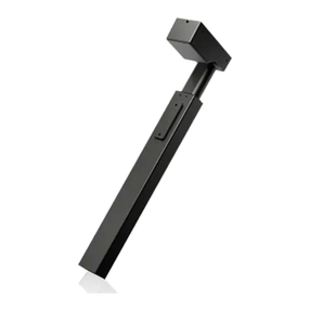
• 1 Lifting column TLT
• 1 Control unit SCU16/56/96
• 1 SBOX power cable EU/US/CH/CN
• 1 RS232 interface cable M/0133976
• 1 Controller I/O cable M/0133975
• 1 EHA3A operating handswitch
• 1 OMRON attachment plate
• 1 bottom mounting plate
• 8 M10x40 screws for mounting plates
• 4 screws M6x20 for OMRON robot
• 2 pins ᴓ 8x20 to align OMRON robot
• Quick start guide
• 1 SBOX
• 1 SBOX key
• 1 SBOX I/O cable
• 1 SBOX to controller power cable
• 1 Ethernet cable
• SBOX mounting attachments
Fig.1
Scope of delivery
*this cable is only intended to connect the Ewellix SBOX with the Ewellix SCU controller
Controller
I/O cable
RS232
cable
SBOX
I/O cable
SBOX Key Ethernet
cable
SBOX to controller
power cable *
SBOX power
cable
Lifting column
SCU Controller
SBOX
Quick start guide
LIFTKIT
QUICK START GUIDE
LIFTKIT
This QUICK START GUIDE does not replace the operating ma nuals of the included products.
Forge neral information and safety instr uctions please refer to installatio n, operation and maintenance manua ls available at
ewellix.com/products/telescopic-pillars/ liftkit .
Qualied personnel can carr y out assigned work and to recognize and p revent possible dangers self-reli antly due to its pro-
fessional training, knowledge and expe rience as well as profound knowledge of app licable regulations.
Setting up LIFTKIT
1. Mount interface plate s to
pillar (top and bottom)
2. Connectall cables
3. InitializeLIFTKIT (First use only!)
LIFTKIT-UR Others
3.1. Press both handswitch but tons at the same
time,u ntil controller beeps (5sec)
3.2.Move pillar downwards until end stop (b eep)
3.3.Move pillar upwards until end stop (be ep)
4. Screw robot to pillar and
installdedicated user
interfacesoft ware
ewellix.com
© Ewellix
All contents of this publication are the property of Ewellix, and may not be reproduced or given to third parties (even extracts) without permission. Although great care has been taken in the
production of this catalog, Ewellix does not take any responsibility for damage or other loss resulting from omissions or typographical errors. The photo may dier slightly in appearance from the
actual product. Due to continuous improvements being made in our products, the product’s appearance and specications are subject to change without notice.
PUB NUM TC-08048-EN-March 2021
Motioncontrol
Controller
Robot
attachment
plate
Electrical
230/120V AC
24V DC
Electrical
230/120V AC
Controller
Robotcontroller
(notincluded
inLIFTKIT-0S)
Robot
attachment
plate
SBOX
EHA31 operating handswitch

7
4.1 Tools required
The following tools are required for the mechanical
installation:
• Hex key size 5 and 6
• Screw driver 2 mm
4.2 LIFTKIT mechanical
setup
Refer to the numbers in 3.1 Scope of delivery, and in the
Fig. 2 for the preparation of the lifting column:
1. Take the lifting column out of the box
2. Loosen and remove 4 transport screws (1) at the bottom
of the lifting column
3. Attach the bottom mounting plate (2) using 4 M10x40
screws (screw 10) on the outer guiding of the lifting col-
umn. Ensure a tightening torque of 40 Nm on these
screws.
4. Fix the bottom (2) plate securely to the ground or a frame
using at least four ground xation holes on the plate (3)
NOTE
Alternatively, if mounting to a SLIDEKIT, attach the bottom plate
with 8x M6 screws to the LIFTKIT's attachment plate.
4.0 Mechanical installation
1
1
1. Transport screws
2. Bottom mounting plate
3. Ground xations holes
4. Top mounting plate
5. UR alignment pins
1
4
3
5
1
2
Fig. 2
Close up of transport screws (left) and the TLT (right)
5. Loosen and remove 4 transport screws (1) at the top of
the lifting column
6. Attach the top OMRON attachment plate (4) using 4
M10x40 screws (screw 10) on the inner guiding tube.
4.0 Mechanical installation

8
LIFTKIT-OM
8
5.0 Initialization of LIFTKIT and
robot installation
LIFTKIT must be initialized before its rst operation. For this,
follow the steps below:
1. Connect the LIFTKIT like the following gure 3. It is rec-
ommended to do the initialization without the robot
mounted on the column. The lifting column has to be
plugged into port 1 and 2 of the SCU.
2. Override of the emergency stop link. Short-circuit the
three wires with the provided clamp as shown in the
gure 4, in order to override the emergency stop link.
3. Press both handswitch buttons simultaneously for about
5 seconds, until the SCU rattles and beeps. Now the col-
umn will run at 50% speed and force.
4. Move the column downwards until it hits the end posi-
tion. The SCU controller beeps.
5. Move the column upwards to the top position until it hits
the end position. The SCU controller beeps.
NOTE
The identied end positions are used as virtual limits, which will
be approached by soft ramps. After successful initialization the
lifting column will move at full speed and full force. If it does
not reach its full stroke or continues to beep, then repeat the
initialization procedure again.
NOTE
If the system connections are changed, a new initialization may
be required
6. If required, insert the 2 alignment pins on the top plate
and press them in (or use a plastic hammer)
7. Align the robot with the alignment pins and x the robot
base with the four screws provided.
Fig. 4
Zoom on the safety I/O calble to override emergency stop
link with provided clamp
white
red
green
yellow/white
yellow
Controller
I/O cable
Ethernet
cable
SBOX
power
cable
SBOX front panel
SCU controller
Handswitch
yellow, congurable output (0V) N° 1
white, congurable output (0V) N° 2
green, congurable output (24V) N° 1
red, congurable output (24V) N° 2
yellow/white
Fig. 3
Digital I/O clamp in robot controller
RS232 interface cable
SBOX
to SCU
controller
power cable
Por t 17
Port 10
Port 12
Port 1 Port 2

9
6.0 Hardware connection SBOX
6.1 Hardware connection SBOX
1. K1.A1 ➞ Congurable output (24V) N°1
2. K2. A1 ➞ Congurable output (24V) N°2
3. K1.A2 ➞ Congurable output (0V) N°1
4. K2.A2 ➞ Congurable output (0V) N°2
5. K1.31 ➞ Read out* N°1
6. K1.32 ➞ Read out* N°1
7. K2.31 ➞ Read out* N°2
8. K2.32 ➞ Read out* N°2
A1 14 24 32
A2 13 23
23 24
13 14
A1 A2
31 32
31
15 16
910 11 1312 14
1
2
3
4
5
6
7
8
6.2 Safety connection
The SBOX has two integrated safety relays with forcibly guided contacts. Their coil and feedback contacts are wired directly
to the I/O connector.
9. Ethernet connector
10. On/O switch
11. Fuse
12. Power In
13. Power Out
14. I/O connector
15. RS232 connector
16. 16. USB port
6.0 Hardwre connection SBOX

10
LIFTKIT-OM
6.3 LIFTKIT connection setup
SBOX
I/O cable
Ethernet
cable
SBOX Robot controller
USB port
SCU
control unit
TLT
Lifting column
Controller
I/O cable
RS232
cable
Port 12
Port 1
Port 2
Po r t 11
Port 10
Port 7
SBOX to controller
power cable
SBOX power
cable
Handswitch
1. Standard operation
yellow (0V)
white (0V)
green (24V)
red (24V)
yellow/white
2. Initialization E-stop override
red
green
yellow/white
yellow
white
1 Out1-24V
2 Out2-24V
3 Out1-0V
4 Out2-0V
5 IN1 read out
6 IN2 read out
7 IN3 read out
8 IN4 read out
Safety
Outputs
Safety
Inputs

11
7.0 Software instruction for Ewellix LIFTKIT Component for TMflow
7.0 Software instruction for Ewellix
LIFTKIT Component for TMow
7.1 Introduction
The Ewellix LIFTKIT component allows customers to inte-
grate the LIFTKIT lifting column’s capabilities with TMow
applications. Currently, there is only one component availa-
ble for LIFTKIT integration: “Command”.
7.2 Installation
Download the zipped component le from the Ewellix web-
site: ewellix.com -> 7th axis for robots -> liftkit -> lift-
kit-om -> Software update
1. 1.Take the zipped component le and place it into a
TMROBOT-formatted USB drive or a network drive that is
mapped to the robot’s Network Service feature.
1.1. For the USB stick to be in TMROBOT format, it
needs to be on the NTFS le system and named
TMROBOT (all-caps), as shown below.
1.2. The Network Service feature looks like this:

12
LIFTKIT-OM
12
2. In the drive of your choosing, place the zipped compo-
nent le into a directory that looks like this, for example:
D:\TM_Export\RobotName\ComponentObject\
Column_Ewellix_LIFTKIT_v01_Command.zip
3. Open the Import/Export menu in TMow, then plug the
USB drive into the robot controller or select the network
drive as shown here:
4. Select “Import”, then select the correct Robot ID. In this
example, the robot ID is simply, “RobotName” based on
the directory above.
5. Select “Component”, then click on the Ewellix column
component, then click “Import”.

1313
6. Go to the Component menu in the robot settings page,
then enable the Ewellix component. Click Save when
done.
7. Now the component is ready for drag-and-drop use with
TMow projects!
7.0 Software instruction for Ewellix LIFTKIT Component for TMflow

14
LIFTKIT-OM
14
7.3 Command Component
The Command component has four primary functions, each
performed in the order listed:
1. Specify Column IP Address (does not recongure the
column’s IP)
2. Get Column Info (such as current status, current virtual
limits, and current position)
3. Set Column Info (such as column type and virtual limits)
4. Move the Column to an absolute position
Command Component & Icon
Column Ewellix LIFTKIT v01 TestProject
User Input Menu

1515
Set_IP
Set_IP Settings
In this menu, click Edit Device to adjust the IP address and
port settings of the LIFTKIT
NOTE
DO NOT select Add or Choose a dierent device, as this will
cause the component to fail.
NOTE
The default IP address of the component matches the default IP
address that the LIFTKIT uses out-of-the-box. This menu should
only needed if the LIFTKIT IP address has been recongured by
the user.
Get_Info
Get_Info Settings
var_GetInfo:
• Function: Determines whether the component will request
information from the column using the “Get” commands
such as get_position and get_type.
• Type: Boolean variable
• Default: true
NOTE
If set to true, this is the rst step that the component will
perform. This means that the information gathered during this
step will be snapshotted before any “Set” commands or motion
commands are issued.
7.0 Software instruction for Ewellix LIFTKIT Component for TMflow

16
LIFTKIT-OM
16
var_SetType:
• Function: Determines whether the component will modify
the column’s current type using the set_type command. If
set to true, this will require both the column and communi-
cation box to be power cycled for the changes to take ef-
fect, and the component will exit immediately after the
type is set.
• Type: Boolean variable
• Default: false
var_Type:
• Function: Sets the value of the column type that will be set
once the set_type command is issued. Use the get_type-
sAvailable command in the Get Info function of the compo-
nent for a list of acceptable column types.
• Type: String variable
• Default: “LIFTKIT-601”
Set_Info
Set_Info Settings
var_SetVirtualLimits:
• Function: Determines whether the component will modify
the column’s current virtual limits settings using the set_
virtualLimits command.
• Type: Boolean variable
• Default: false
var_LowerLimit:
• Function: Sets the lower virtual limit used in the set_virtu-
alLimits command.
• Type: Float variable
• Default: 0
var_UpperLimit:
• Function: Sets the upper virtual limit used in the set_virtu-
alLimits command.
• Type: Float variable
• Default: 700

1717
Move_Absolute
Move_Absolute Settings
var_MoveAbsolute:
• Function: Determines whether the component will issue
the moveTo_absolutePosition command to the column.
• Type: Boolean variable
• Default: false
var_AbsolutePosition:
• Function: Sets the absolute position to which the column
will move when issued the moveTo_absolutePosition com-
mand.
• Type: Float variable
• Default: 0
var_MoveTimeout_ms:
• Function: Sets the amount of time in ms for the column to
reach its commanded position before timing out.
• Type: Integer variable
• Default: 10000
Advanced_Settings
Advanced Settings
var_Position_Tolerance:
• Function: Sets the maximum allowable dierence be-
tween the column’s commanded position and its actual
position once its motion is complete.
• Type: Float variable
• Default: 20 (units are in mm)
7.0 Software instruction for Ewellix LIFTKIT Component for TMflow

18
LIFTKIT-OM
18
var_GetPosition:
• Function: Reports the current absolute position of the
LIFTKIT.
• Type: String Array
• Default: empty
var_GetStroke:
• Function: Reports the maximum stroke of the LIFTKIT unit.
• Type: String Array
• Default: empty
var_GetVirtualLimits:
• Function: Reports the currently congured virtual upper
and lower limits for the LIFTKIT.
• Type: String Array
• Default: empty
var_GetType:
• Function: Reports the currently congured LIFTKIT type. If
the reported LIFTKIT type is dierent from what the actual
LIFTKIT unit should be, then this can be recongured us-
ing the Set_Type command within the Set_Info function.
• Type: String Array
• Default: empty
var_GetTypesAvailable:
• Function: Reports the available types of the LIFTKIT that
can be used with the Set_Type command. If the purchased
LIFTKIT unit’s type does not exist in this list, please con-
tact Ewellix customer support.
• Type: String Array
• Default: empty
var_ErrorCode:
• Function: The error code that is output when there is an
error (See Appendix A for a list of LIFKIT component error
codes)
• Type: Integer variable, ranges from 4000-4005 (or 0 if
there is no error)
• Default: 0
var_PreviousPosition:
• Function: If the Move_Absolute function is used, this vari-
able will store the LIFTKIT’s current absolute position be-
fore moving to the commanded position.
• Type: Float variable
• Default: 0
var_WaitTime_ms:
• Function: Sets the wait time in milliseconds. Wait time is
the amount of delay time required between each serial
command sent from TMow to the column. In newer ver-
sions of TMow, this is referred to as “Extra Idle Time”.
• Type: Integer variable
• Default: 50 ms
var_MaxReceiveTime_ms:
• Function: Sets the maximum receive data time in millisec-
onds. Max receive time is the amount of time TMow will
wait for data to be received in the buer for reading before
timing out.
• Type: Integer variable
• Default: 50 ms
Imported Variables
Imported Variables
var_GetStatus:
• Function: Reports the current status of the LIFTKIT, used
in all three functions of Get_Info, Set_Info, and Move_Ab-
solute. If multiple functions are used in one component in-
stance, then the value of GetStatus will be overwritten
multiple times.
• Type: String Array

1919
Typical Usage
Initial Installation and Testing
Upon the installation of the column with the TM robot, the
Command component should be used by itself in an empty
project to troubleshoot any connection issues and to test if
the commands are working. Use the following steps to get
the column running:
1. Create a new project and drag-and-drop the component
into the ow.
2. If the column’s IP address has been changed from the
default, specify the new IP address in the component.
3. Run the project with the Get_Info function set to true
and the other functions set to false (this is the default
conguration of the component).
a. If there is an Error Code displayed, follow the error
code troubleshooting tips and repeat Step 3 until the
column gives a response. See Appendix A for a list
of LIFTKIT component error codes.
b. If there is a response from the column other than
“READY”, the connection to the column was suc-
cessfully established, but further action is required
based on the response given. Depending on the col-
umn’s current state, it may be possible to issue the
set_type and set_virtualLimits commands with the
component. Refer to the Ewellix LIFTKIT manual for
more details on the available LIFTKIT commands, al-
lowed states, and responses. After each trouble-
shooting step, repeat Step 3.
c. If the response from the column is “READY”, then it
is now possible to send it motion commands.
4. If needed, use the Set_VirtualLimits command to set the
appropriate virtual limits of the column.
5. Test the column’s motion by using the Move_Absolute
function to command the column to various positions
within the range of the virtual limits.
Regular Operation
The component can be used multiple times throughout a
TMow project to get the current column status via the Get_
Info function or to send the column motion commands with
the Move_Absolute function. The relevant imported varia-
bles will be updated as the ow moves through the
component.
NOTE
If the component is used more than once in a project for one
LIFTKIT device, then the “Inherit old component” option must
be selected when dragging and dropping each component after
the rst one into ow. This is because the LIFTKIT cannot accept
multiple connections to the same socket.
NOTE
It is not recommended to use the Set_Info function during
regular operation unless the virtual limits need to be
recongured regularly for an application.
7.0 Software instruction for Ewellix LIFTKIT Component for TMflow

20
LIFTKIT-OM
20
7.4 Error Codes
Error Code Name Description Troubleshooting
4000 Connection Error Could not connect to the column when
the ow entered the component.
Check the following:
1. Column is powered on.
2. Column is connected to TM control box Ethernet port
directly or via an Ethernet hub.
3. The correct IP address and port number were selected
in the Set_IP settings of the component.
4001 Connection Timeout Connection to the column timed out. The connection was established when the ow entered the
component, but the column did not respond to the
component commands within the timeout period. Check the
following:
1. No power or communication cables were removed from
the column during operation.
2. The Set_IP settings are set for the column and not for
another device on the network.
3. The MaxReceiveTime_ms variable values and WaitTime_
ms values are large enough for the column to nish
processing and sending the results to the TM.
4002 Invalid State Column is in an invalid state for the
specied command.
See Ewellix LIFTKIT manual for details.
4003 Error Response
Received
Column issued an error response for
the specied command.
See Ewellix LIFTKIT manual for details.
4004 Motion Timeout The motion timeout period was reached
before the column could issue the
"READY" response to indicate
completed motion.
Check the following:
1. The MoveTimeout_ms value is large enough for the
column to complete its motion.
2. The column is performing the commanded motion in the
expected way and the status of the column is "MOVING"
during the motion.
4005 Position Tolerance
Exceeded
The dierence between the
commanded position and the actual
position is greater than the specied
Position_Tolerance value.
Check the following:
1. The Position_Tolerance value is large enough for the
column to realistically handle during operation but without
hurting the application.
2. The column is performing the commanded motion in the
expected way.
Table of contents