Schako RMS User manual

Ferdinand Schad KG
Steigstraße 25-27
D-78600 Kolbingen
Telephone + 9 (0) 7 63 - 980 - 0
Fax + 9 (0) 7 63 - 980 - 200
info@schako.de
www.schako.de
Smoke detection system
Model RMS

Contents
Construction subject to change. No return possible!
Smoke detection system RMS
09/11 - 2 27.03.2019Version:
Description ........................................................................................................................................3
Application .................................................................................................................................................................................3
Advantages .............................................................................................................................................................................3
RMSII-L .....................................................................................................................................................................................
Function (special scattered light method) ..................................................................................................................................
Construction ..............................................................................................................................................................................5
Accessories ................................................................................................................................................................................5
Fastening ...................................................................................................................................................................................5
Dimensions ........................................................................................................................................5
Technic l d t ....................................................................................................................................8
Smoke detection system (-RMS) ...............................................................................................................................................8
Relay module (-RM) ..................................................................................................................................................................8
M inten nce / Inspection ..................................................................................................................... 10
Order det ils .................................................................................................................................... 11
Specific tion texts .............................................................................................................................. 11

Smoke detection system RMS
09/11 - 3
Construction subject to change. No return possible!
27.03.2019Version:
Description
Applic tion
The SCHAKO smoke detection system consists of the smoke
detector RMSII-L nd the rel y module RM V4.00 nd is used
in pl ces where, t the e rliest possible st ge of fire (upon
occurrence of cold smoke of < 72°), triggering nd switching
oper tions re to be controlled utom tic lly. It c n be fitted
to ventil tion ducts. If detected, the prop g tion of smoke in
the ir duct system is prevented for the most p rt by closing
the fire or smoke d mpers. The alarm message is transmitted
via a potential-free contact and interrupts the electric circuit to
the electric trigger devices (magnetic clamps, spring return ac-
tuators) or to pneumatic drives. The connected fire d mpers
nd smoke d mpers re closed. Only trigger devices working
by the "zero-current closed/ depressurised closed" working
principle must be connected to the RMS system. The smoke
detectors and the connected trigger and switch devices are sup-
plied jointly with power from a relay module 230 AC and a sec-
ondary 2 V DC within a protection area.
The smoke detectors remain in alarm condition after being trig-
gered, even after the normal ambient conditions have been re-
stored. The smoke detectors will not return to their monitoring
status until the relay module is reset.
The measurement takes place outside the smoke detector hous-
ing, thus not requiring ny detection ch mber. Approved for
ventilation ducts of air velocities between 1 m/s and 20 m/s.
Adv nt ges
Industrial property rights owned by SCHAKO:
Extern l monitoring is done by
the VdS Sch densverhütung GmbH Köln (VdS D m ge Pre-
vention Br nch, Cologne)
When integr ting SCHAKO components into customer f cili-
ties, ny comp tibility problems re not our responsibility
nd must be elimin ted by the customer.
Inst ll tion nd mounting
Inst ll tion in duct
Fig. front side
Fig. lateral side
The smoke detector must be installed such that it is permanently
located in the air flow (not in the inspection opening of the fire
d mper).
- As no detection chamber is required for measurements, no
medium flows through the smoke detector and deposits can
only be formed on the safety glass, allowing easy cleaning.
- Fitted flush with the duct.
- Automatic tampering detection.
- Self-function test of the transmitter and receiver sensors. A
defect is displayed.
- When a power, processor or system failure occurs, a fault
message is displayed simultaneously with an alarm message.
- Includes system monitoring (watchdog).
- Bus connection possible via potential-free contacts.
- Connection to the communicative Signalling and Switching
Bus System + Easy Bus possible.
- Maintenance required once a year
- Patent: DE 199 51 03 A1
- Registered utility model: 20023533.8
- Patent: EP 122 6 1
- VdS Approval: G209206
Air flow direction in duct
Air flow direction in duct

Smoke detection system RMS
09/11 - 4
Construction subject to change. No return possible!
27.03.2019Version:
Inst ll tion rr ngement nd mounting
The smoke detector must be fitted free of vibration if possible.
When charged with steam, disinfectant, dust, soot (exhaust
gases) or dew, an alarm or fault message is triggered.
Assembly in ducts
When fitting the RMS
ΙΙ
-L smoke detector, c re must be t ken
th t in 100 mm r dius round the detector, nothing c n re-
flect the emitted sensor sign l.
Connection
Connecting the power supply. When the output voltage is active,
the orange operating indicator lamp will flash.
Note
Before the first startup of the smoke detector, the ducts must be
cleaned so as to avoid any accidental alarm message.
The relay modules are equipped with a controller with power
limiter and thermal protection. When a short-circuit occurs, the
controller switches off the output voltage. An interruption in the
mains supply voltage or the "+" output line will restore the func-
tion of the smoke detector.
After fitting the smoke detector RMSΙΙ-L on site ready to oper-
ate, an acceptance test immediately prior to putting the fire
damper or smoke detector into operation must establish that the
installation conforms to the regulations and that the smoke de-
tector functions properly, especially that all components inter-
act correctly. The acceptance test must be documented by the
building owner of the ventilation system. The documents must
be filed by the building owner/operator of the ventilation sys-
tem.
For maintenance, service, retrofitting, etc., inspection openings
in sufficient number and size must be provided on site.
RMSΙΙ-L
Function (sc ttered light principle)
Two sensors in the smoke detector send out a light beam and
measure if the air on the front of the safety glass is contaminat-
ed with smoke or other particles. Before triggering an alarm,
various measurement cycles must be carried out, during which
the contamination in the air must be measured. If the contami-
nation is not permanently present, then the internal measure-
ment cycle counter is reset. The response sensitivity of the
smoke detector is set inalterably ex works. The alarm output is
a potential-free change-over contact. The smoke detector can be
reset to the ready-to-operate mode by remote control.
A power failure at the smoke detector can be displayed at the
central unit. In this case, the electric circuit for the release de-
vice is interrupted on the connected fire dampers, and the
dampers are closed. Tampering with the smoke detector, for ex-
ample by taping the sensors, is detected and, if required, report-
ed to the central unit via a potential-free contact (error output).
Deposits on the safety glass of the smoke detector are detected
and evaluated. When a certain degree of soiling is exceeded, it
is reported as a fault message to the switchboard via a potential-
free contact. In this way, the smoke detection system monitors
itself.
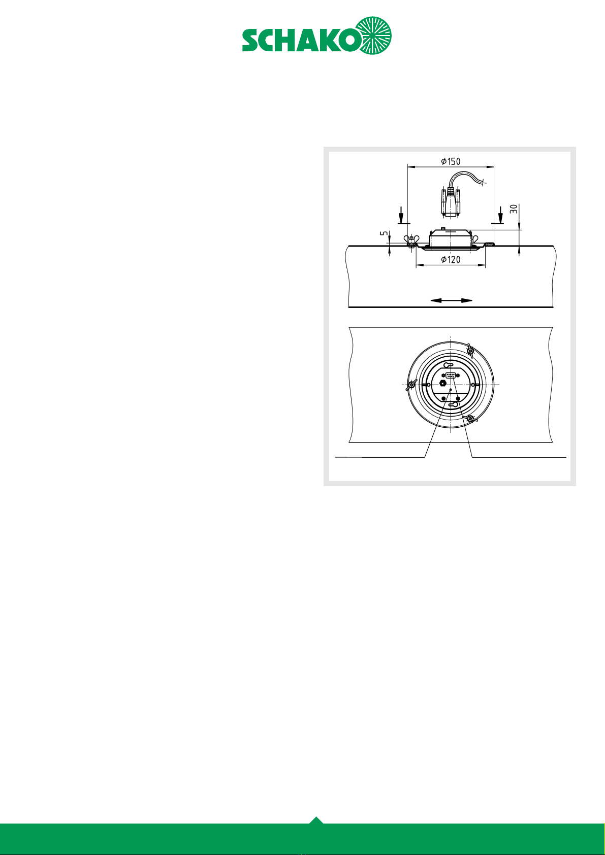
1. Establish smoke detector position (not in the inspection
opening of the fire damper), and mark the middle.
2. Cut out a hole of 120 mm in diameter.
3. Drill mounting holes (only when installed on site in the ven-
tilation duct).
. Insert the delivered insulating sleeves into the mounting
holes.
5. Fit smoke detector with mounting frame and seal, fasten with
thumb nuts or Parker screws.
6. During installation, observe air flow direction.
7. Carry out electrical wiring according to wiring diagram.
8. Before putting the RMS
ΙΙ
-L into operation, the duct system
must be cleaned completely. Care must be taken that the
glass front is sprayed again with an antistatic spray after wip-
ing it clean with a damp cloth.
Smoke detection system RMS
09/11 - 5
Construction subject to change. No return possible!
27.03.2019Version:
Construction
Accessories
F stening
Dimensions
Smoke detection system RMS
ΙΙ
-L
for installation in rectangular ducts without assembly part!
Smoke detector base
- Polycarbonate
Connecting cable
- 2.0 m with 9-pin Sub D plug. The 9-pin Sub D terminal for
the electric supply and trigger lines is located inside the
base.
Individual display
- LED on duct exterior
Mounting frame
- Sheet steel, with seal
Assembly part type EBT
- for installation flush with the duct, made of galvanised
sheet steel.
- Housing leakage according to DIN EN 1751, class B, at a
duct pressure of up to 1000 Pa.
Assembly part (-REBT / -REBTF)
- for installation in round ducts, made of galvanised sheet
steel.
- Housing leakage according to DIN EN 1751, class B, at a
duct pressure of up to 1000 Pa.
- model
- without flange (-REBT), with rubber lip seal made of
special rubber.
- with flange (-REBTF), on both sides, to EN 12220.
Screw connection
- with thumb nuts or Parker screws
SUB-D plug
9-pin + correspondence
LED for displaying
functional, fault and
alarm message
AIR FLOW DIRECTION
(Duct opening)
ca.

Smoke detection system RMS
09/11 - 6
Construction subject to change. No return possible!
27.03.2019Version:
Accessories
with ssembly p rt (-EBT), for fire damper installation
- Inst ll tion in duct topside
The smoke detector must always be assembled in the assembly
part type EBT on the operator side (trigger device, drive) (not in
the inspection opening of the fire damper).
- Inst ll tion in duct side w ll
The dimension L depends on the height H (mm).
Section A-A / off-centre ssembly
for B > 700
Duct topside
Min. space required
Section A-A / centre ssembly
for B < 700
EBT
1.) min. 100
H
(mm)
L
(mm)
200 - 750 180
800 210
Section C-C
Duct topside
EBT
1.) min. 100
Smoke detection system RMS
09/11 - 7
Construction subject to change. No return possible!
27.03.2019Version:
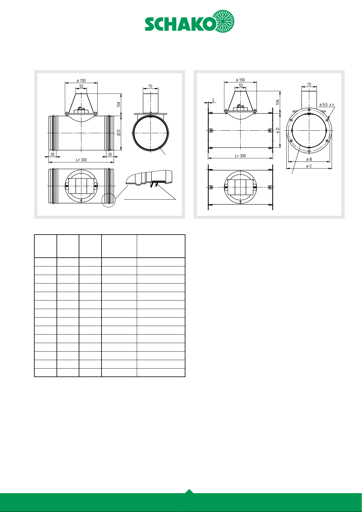
with ssembly p rt (-REBT), for installation in round ducts
- without fl nge, with rubber lip seal.
Av il ble sizes REBT / REBTF
1.) painted black matt on the inside
with ssembly p rt (-REBTF), for installation in round ducts
- with fl nge on both sides, to EN 12220.
NW øD
(mm)
øC
(mm)
øB
Bolt circle
(± 0.5mm)
n
Number of bores
ø9.5 (± 0.5mm)
100 98 150 132
125 123 175 157
140 138 190 172 6
160 158 210 192 6
180 178 230 212 6
200 198 250 233 6
224 222 27 257 6
250 2 8 300 283 6
280 278 3 0 317 8
315 313 375 352 8
355 353 15 392 8
400 398 60 38 8
450 8 510 88 8
500 98 560 538 8
with rubber lip seal as a
standard
1.)
1.)

Smoke detection system RMS
09/11 - 8
Construction subject to change. No return possible!
27.03.2019Version:
Technic l d t
Smoke detection system (-RMS)
Individu l displ y - LED displ y:
Connection ssignment of the 9-pin SUB-D plug:
The rel ys drop off when n l rm / f ult or power cut oc-
curs.
Rel y module (-RM)
The RMS
ΙΙ
-L is connected to the power supply by means of a
relay module (9-pin SUB-D socket). Moreover, the reset button
RST and the test switch have already been mounted on the relay
module. This makes it easier to check the fire damper closing
function via the test switch and/or to reset the alarm message
via the reset button RST. Additional terminal strips for spring re-
turn actuator and / or fan disconnection or other switching op-
erations will shorten the installation time and prevent wrong
wiring.
A 2 V spring return actuator can be activated via the 3-pin AMP
plug (standard Belimo BLF, BF, BFG).
RM V 4.00
Operating voltage: 2 V DC (+15% -20%)
Residual ripple: < 20%
Max. current consumption: 25 mA
Switching contacts: - 1 alarm output (potential-free
change-over contact)
- 1 fault output (potential-free
change-over contact)
Max. switching voltage: 100 V DC / 125 V AC
Max. switching current: 1.0 A
Max. switching power: 30 W / 62.5 V A
Operating temperature and
ambient temperature:
0 °C to +60 °C
Protection type according
to DIN 0050:
IP 0
Weight: 0.2 kg
Storage temperature: max. 75°C
Relative humidity: 10 - 90%
flashing orange = Function
permanently red = Alarm
permanently orange = Fault / Soiling
Assign-
ment Rel y Me ning
de-energised
oper ting
1 - - GND
2 Relay contact work contact fault
3 Relay contact centre contact fault
Relay contact rest contact fault
5 - - Test switch to GND
6 Relay contact rest contact alarm
7 Relay contact centre contact fault
8 Relay contact work contact alarm
9 - - +2 V
Operating voltage: 230 V AC, 50 Hz
Dimensioning: 23 VA
Ambient temperature: 0- 0°C
Relative humidity: 0-90%
Degree of protection: IP30
Connection
LED fault
F1 fuse
secondary
LED operation
Button reset
LED alarm
Manual release button
Smoke detection system RMS
09/11 - 9
Construction subject to change. No return possible!
27.03.2019Version:
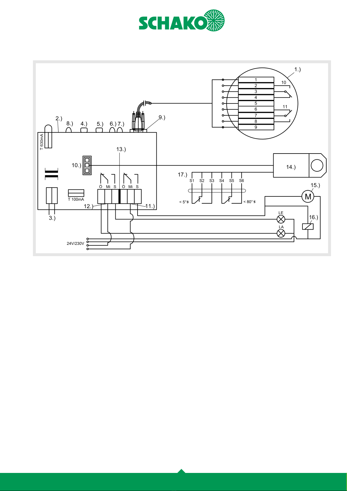
Circuit di gr m of rel y module
Cont ct ssignment RMS-L:
The de-energised state is shown. For relay module, also the
alarm or fault condition.
2 V AC/DC
2 V DC 5A
250 V AC 5 (1)A
230 V AC 50 Hz
Primary
2 V AC
230 V AC
Second-
1.) Smoke detectors
2.) Relay module
3.) Mains connection
.) Reset button
5.) Manual release
6.) LED fault
7.) LED alarm
8.) LED operation
9.) Connection RMS
10.)
AMP plug for 2 V AC/DC actuators (max. 10 VA)
11.) Selector switch 1, e.g., actuator
12.) Selector switch 2, e.g., light
13.) Contact load of the selector switches
1 .) Spring return actuator 2 V AC/DC for fire damper.
SCHAKO product or external product (for the techni-
cal data, please refer to the motor data sheet)
15.) Spring return actuator 2 V AC/DC / 230 V AC SCHA-
KO product or external product (optional) (for the
technical data, please refer to the motor data sheet)
16.) Magnetic clamp / pneumatic valve (optional)
17.) Limit switch spring return actuator
(connection is fitted in a T-piece socket on-site)
1 GND
2 Work contact
3 Centre contact
Rest contact
5 Test switch / RST
6 Rest contact
7 Centre contact
8 Work contact
9 +2 V
10 FAULT
11 Alarm
Ö = NC contact
Mi = Centre contact
S = NO contact
LA = Ventilation OFF (option)
LE = Ventilation ON (option)

Smoke detection system RMS
09/11 - 10
Construction subject to change. No return possible!
27.03.2019Version:
M inten nce / Inspection
Maintenance of the smoke detection device for fire and smoke
dampers must be carried out once a year or after a fault mes-
sage, due to contamination.
Note
Installation and wiring must be carried out by authorised elec-
tricians only. The agreed regulations of the technic, safety and
accident prevention regulations as well as the VDE guidelines,
regulations of the local EVU's and the wiring instructions and
connection plans of the manufacturer, must be adhered to when
installing, wiring and commissioning. When wiring the junction
boxes, make sure to earth the shielding. The smoke detector
must be used according to this brochure description.
M inten nce instructions
The SCHAKO smoke detector type RMS
ΙΙ
-L permanently moni-
tors itself and gives an error warning to the central unit if there
is a mechanical or electrical defect or if it is too heavily soiled.
In case of a power failure of the smoke detector, a fault message
is also sent to the central unit. This permanent self-monitoring
allows a yearly maintenance interval.
M inten nce includes the following ctions:
Inspection instructions
The SCHAKO smoke detector type RMS
ΙΙ
-L permanently moni-
tors itself and gives an error warning to the central unit if there
is a mechanical or electrical defect or if it is too heavily soiled.
When a power failure of the smoke detector occurs, a fault mes-
sage is also sent to the central unit.
1. The type of use and installation situation must be checked
for the first time during commissioning and then after mod-
ification.
2. The electrical connections must be checked for correct con-
nection and perfect condition.
3. Checking whether the diode on the fitted smoke detector or
relay module flashes orange, thus signalling ready operat-
ing state.
. Electrical functionality control
The power supply of the smoke detector must be discon-
nected by removing the 9-pin Sub-D plug or by pressing the
reset button on the relay module. This causes the smoke de-
tector to send an alarm to the connected locking device,
which will close automatically. The diode on the smoke de-
tector or relay module is no longer lit. As soon as the power
supply has been restored and the alarm has been acknowl-
edged by pressing the reset button, the smoke detector
must return to the ready operating state, and the diode on
the smoke detector and / or relay module must flash orange
5. Fault control
On the smoke detector RMS
ΙΙ
-L, the transmitter and receiv-
er sensors must be covered. The diode on the smoke detec-
tor lights up permanently in orange. The fault contact
reports a fault. After that, the cover must be removed again.
The smoke detector must again return to the ready operat-
ing state, and the fault message is reset at the central unit.
6. Functionality control using test aerosols
When the smoke detector is fitted to ducts, a test aerosol
must be applied to the smoke detector through an inspec-
tion opening.. This must be done by applying the test aero-
sol to the smoke detector increasingly in pulsed form for
about 10 sec. When the alarm threshold values is exceeded,
an alarm message will be triggered, and the connected lock-
ing devices must close automatically. The diodes on the
smoke detector and on the relay module must light up in
red. After the test aerosol components in the surrounding
air of the smoke detector have decomposed to such an ex-
tent that the value drops again below the alarm threshold
value, the alarm message is still displayed on the smoke de-
tector and on the relay module. This is why the smoke de-
tector must be activated again by pressing the reset button
on the relay module. As soon as the diode on the smoke de-
tector type RMS
ΙΙ
-L flashes in orange again and the red LED
on the relay module goes out, the smoke detector is ready
to operate again.
7. Elimination of defects
If defects have been detected during maintenance, they
must be eliminated immediately. Defective components
may only be replaced with original parts delivered by SCHA-
KO. Repair of the smoke detector and of the relay module
must be carried out only by the appliance manufacturer.
If any of the connected shut-off devices are not closing,
even when the smoke detector and the relay module operate
faultlessly, then the shut-off devices themselves must be
checked.
8. If the maintenance and inspection instructions of this tech-
nical documentation are used for the annual check of the
functioning of the SCHAKO smoke detection system (RMS),
the smoke detector can remain in use until an inadmissible
deviation is detected.

Smoke detection system RMS
09/11 - 11
Construction subject to change. No return possible!
27.03.2019Version:
Order det ils Specific tion texts
Smoke detection system type RMS, with annual maintenance,
for installation flush with the duct or fire damper installation
with assembly part type EBT (extra charge), with maintenance
cover. Consisting of a housing, base, cover plate, similar to RAL
9010 (white), a mounting frame made of sheet steel with seal
and with connecting cable 2.0 m long with Sub-D 9-pin connec-
tion. For use on fire and smoke dampers, with electric or pneu-
matic release devices working by the zero-current closed /
depressurised closed functional principle, and with magnetic
clamp and lifting magnet.
Two sensors self-monitoring permanently for correct function-
ing measure the air contamination due to smoke with a special
scattered light procedure outside the housing, without using a
detection chamber. They measure the degree of contamination
at two points on the surface of the safety glass. Alarm and fault
messages each take place via a potential free change-over con-
tact. Manual triggering of the smoke detector possible via a re-
set button (at an extra charge).
Fastening with screw mounting (SM) (with thumb nuts or Park-
er screws).
Includes relay module (-RM) for supplying power and for alarm
transmission incl. test switch and reset button
- with transformer for connection to 230 V AC, 50 Hz
Connection 2 V DC.
Product: SCHAKO type RMS
Accessories:
Accessories:
Order ex mple
RMS
ΙΙ
-L-RM
Unless st ted otherwise, the thick-fr me model will be
delivered!
Assembly part
for duct installation
-EBT
Relay module
-RM
incl. RST
Smoke detection system
Type RMS
ΙΙ
-L
without flange
with rubber lip seal
-REBT
Assembly part
for duct connection
with flange, on both sides
according to EN 12220
-REBTF
- Assembly part (-EBT) for simple duct installation in front of
the fire damper. Consisting of galvanised sheet steel with
connection flanges. Housing leakage according to DIN EN
1751, class B, at a duct pressure of up to 1000 Pa
- Assembly part (-REBT / -REBTF) for simple installation in
round ducts in front of the fire damper. Consisting of galva-
nised sheet steel. Housing leakage according to DIN EN 1751,
class B, at a duct pressure of up to 1000 Pa.
- without flange (-REBT), with rubber lip seal made of spe-
cial rubber.
- with flange (-REBTF), on both sides, to EN 12220.
This manual suits for next models
1
Table of contents
Popular Smoke Alarm manuals by other brands


Interlogix
Interlogix CDX-135Z installation manual

Tyco
Tyco DSC FSD-210 Series Installation and operating instructions

Smartek
Smartek NUBI 4.0 manual

Ei Electronics
Ei Electronics Ei 105B instructions

Teletek electronics
Teletek electronics SensoIRIS T110IS installation instructions

Honeywell
Honeywell 5800COMBO Installation and setup guide