The JA-82ST wireless combined smoke and heat detector MZZ57307
c. The control panel confirms the enrollment with a flashing of the “A“
LED on the system keypad at the corresponding position.
d. Exit the Enrollment mode by pressing #.
5. Insert the detector into the plastic base. The detector can be inserted into
the plastic base only in one position, which is marked with arrows (4) on
both plastic parts, provided that all three batteries are inserted. Close the
detector cover by turning it clockwise (2). When the detector is fully
secured to the base, a control LED lights up (3), which indicates an
automatic detector test. During this period of time, the detector doesn’t
detect anything. The test ends when the LED shuts down (3), the detector
becomes fully operational. A possible detector fault may be indicated, see
the Fault indication chapter.
Note: The detector can also be enrolled into the system by entering its
serial number (5) in the O-Link program. (Enter the last 8 digits under the
bar code).
Detector setting
The detector properties can be set in the Detectors window in the
O-Link program and with the configuration terminals.
You can choose a type of reaction, to which the system will react upon
the detector’s activation, in the Reaction option in the Detectors tab.
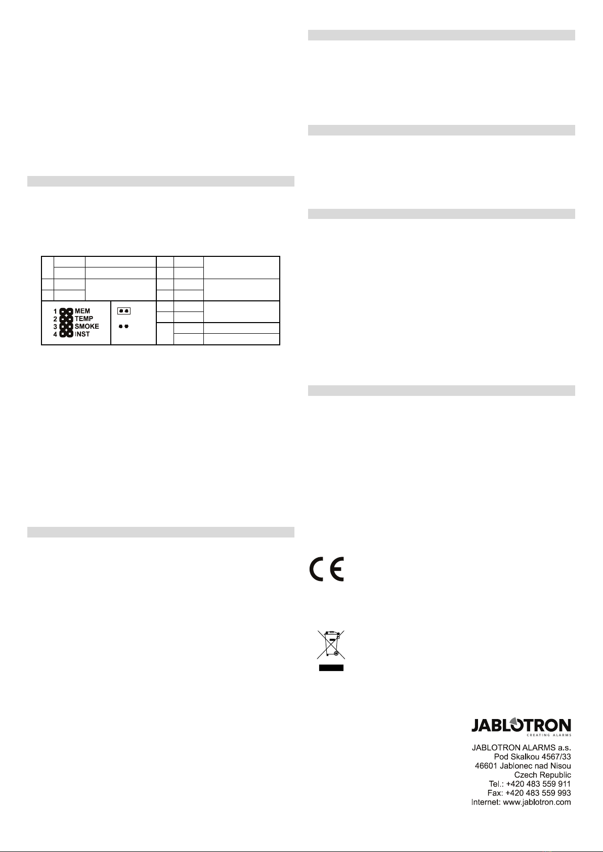
The terminals in the detector can set other options:
1
Memory disabled
Smoke(EN 54-7) or
heat (EN 54-5)
Memory enabled
Smoke only (EN 54-
7), (not heat)
Heat only (EN 54-5)
(not smoke)
2 ON
conditions at the same
4
Instant alarm
Fire alarm
Jumper 1 MEM - Signaling the alarm memory. The signaling LED remains
active for 24 hours after the reason for the alarm ceases to exist.
Jumper 2 and 3 TEMP and SMOKE - The combination of these
configuration jumpers defines how the detector will react to smoke or heat.
Jumper 4 INS jumper sets the reaction of the system when activated:
•FIRE = alarm is triggered no matter if the system is set or unset
•INST = alarm is triggered only when the system is set. This is
used in places where we usually expect smoke to appear
(fireplaces, cigarettes…). Warning – when unset, the system
doesn’t monitor for a fire hazard
The jumper only has an effect if the detector has a natural reaction
assigned to its address in the Oasis control panel. It also has no effect
when used with a UC-8x or AC-8x receiver.
Warning: This device cannot be considered a fire detector when it’s
configured to the INST reaction. The control panel signals an alarm only
when it’s set. The detector signals an alarm with a quickly flashing red
LED (approx.8 times/s) regardless of the control panel status.
Fire alarm
Optical detector: When smoke enters the detector, an alarm is triggered,
and it is signaled with a rapidly flashing red LED light (approx. 8 times per
second). The indication lasts until the room is ventilated (thus also ventilating
the detector’s detection chamber).
Heat detector: When the temperature rises above a set limit, an alarm is
triggered, and it is signaled with a rapidly flashing red LED (approx. 8 times
per second). The indication lasts until the temperature drops (e.g. when the
room is ventilated).
Alarm memory: If enabled, LED alarm indication continues flashing
slowly (approx. 4 times per second) for a further 24 hours after the alarm
stops. The indication can be terminated by opening the detector cover by
turning it anti-clockwise and activating the tamper sensor.
WARNING! The control panel must be switched to Service or Maintenance
mode otherwise a Tamper alarm will be triggered.
Tamper alarm: When the detector cover is opened, the detector sends a
tamper signal, unless the control panel is in Service or Maintenance mode.
Detector testing and maintenance
The functionality of the optical part of the detector can be tested with a test
spray for smoke detectors. Functionality of the heat sensor can be tested with
a hairdryer. In case the detector is configured to both conditions, it’s
necessary to conduct both spray and hairdryer tests at the same time. The
test should be carried out once in 30 days. The detector’s cover should be
cleaned regularly from cobwebs and dust. No additional maintenance is
necessary.
Warning: never test the detector with fire inside a building.
Battery replacement
The system sends a report automatically when the battery is low. Optical
indication then flashes briefly once every 30 seconds. Remember to switch
the system to Service mode before changing the batteries (otherwise a
tamper alarm will be triggered). It is always essential to replace all three
batteries. Use the same type and the same brand for all of them. Wait for 30
seconds in order to let the detector’s circuitry discharge before inserting new
batteries.
Fault indication
The detector checks its functionality. When a fault is detected, LED
indication immediately flashed 3 times and then briefly 3 times every 30
seconds (a failure of the automatic functionality test is signaled the same way,
see the Installation chapter). The error found may be caused by a fault of the
detection chamber, the temperature of the environment being out of the
operating temperature range or other faults of the detector.
An operating temperature range fault will disappear the moment the
temperature of the environment turns back to normal.
Other faults found are indicated as a fault even after their cause has gone.
The fault indication can be stopped by the functionality test. The functionality
test is triggered by opening the detector cover (fig 6-1), removing the lower
plastic part and putting it back (fig 6-2). If this test results in a fault, send the
detector to the repair service.
WARNING! The control panel must be switched to Service mode otherwise
a Tamper alarm will be triggered
The detector will alert you in case of low batteries by an LED flashing briefly
once every 30 seconds.
Technical specifications
Power 3 x alkaline battery type LR6 (AA) 1.5 V
Warning: Batteries are not included
Typical lifetime approx. 3 years
Communication frequency 868.5 MHz, OASiS protocol
Communication range approx. 300 m (unrestricted area)
Dimensions diameter 126 mm, height 50 mm
Weight 140 g (without batteries)
Smoke detection optical light scattering
Smoke detector sensitivity m = 0.11 - 0.13 dB/m according to EN 54-7
Heat detection class A2 according to EN 54-5
Alarm temperature +60 °C to +70 °C
Operating temperature range -10 °C to +80 °C
Complies with EN 54-5, EN 54-7, EN 54-25,
Also complies with ETSI EN 300220, EN 50130-4
EN 55022, EN 60950-1
Can be operated according to ERC REC 70-03
15 1293-CPD-0250
JABLOTRON ALARMS a.s. hereby declares that the JA-82ST is in a compliance with
the relevant Union harmonisation legislation: Directives No: 2014/53/EU, 2014/35/EU,
2014/30/EU, 2011/65/EU. The original of the
conformity assessment can be found at
www.jablotron.com - Section Downloads.
Note: Although this product does not contain any harmful materials
we suggest you return the product to the dealer or directly to the
producer after use.


