Schaudt LAS 1218-2 Specification sheet

Date: 06.11.2014
ESchaudt GmbH, Elektrotechnik und Apparatebau, Planckstraße 8, 88677 Markdorf, Germany, Tel. +49 7544 9577-0, Fax +49 7544 9577-29, www.schaudt--gmbh.de
810.523 BA / EN
Instruction Manual and Installation
Instructions
LAS 1218-2 Battery Charger
Table of contents
1 Instruction manual 2......................................
1.1 Safety information 2......................................
1.2 Introduction 3............................................
1.3 Operation 4..............................................
1.4 Maintenance 7...........................................
2 Installation instructions 8..................................
2.1 Introduction 8............................................
2.2 Mechanical installation 8...................................
2.3 Electrical connection 9....................................
2.4 Initial use 16..............................................
2.5 Technical details 17........................................
2.6 Storage - Packaging - Transportation 18......................
Appendix 19..............................................

Instruction Manual and Installation Instructions LAS 1218-2
2
Date: 06.11.2014 810.523 BA / EN
1 Instruction Manual
1.1 Safety Information
1.1.1 Meaning of safety symbols
Y
DANGER!
Failure to heed this warning may result in death or serious injury.
Y
WARNING!
Failure to heed this warning may result in personal injuries.
Y
ATTENTION!
Failure to heed this warning may result in damage to the device or connec-
ted consumers.
1.1.2 General safety information
The device is state-of-the-art and complies with approved safety regulations.
Nonetheless, personal injuries or damage to the device may occur if the sa-
fety instructions contained herein are not followed.
Ensure that the device is in perfect working order before use.
Any technical faults which may impact personal safety or the safety of the
device must be rectified immediately by qualified personnel.
Y
DANGER!
230V mains voltage carrying parts.
Danger of death due to electric shock or fire:
F
The electrical system of the motorhome or caravan must comply with
current DIN, VDE and ISO regulations.
F
Connect devices rated at 230V to the 230V supply in line with national
installation regulations.
F
Never modify the device.
F
Only carry out electrical work once the 230V supply has been discon-
nected.
F
Never try to start the device using a defective mains cable or with a
faulty connection.
F
Never carry out maintenance work on live devices.
F
Ensure proper electrical connections are made.
F
Ensure correct electrical fuses are used.
F
The mains connection line may only be replaced by an authorised cu-
stomer service department or by qualified persons.

Instruction Manual and Installation Instructions LAS 1218-2
3
Date: 06.11.2014
810.523 BA / EN
Y
WARNING!
Hot components!
Burns:
F
Only change blown fuses when the device is completely de-energised.
F
Only replace blown fuses once the cause of the fault has been identi-
fied and rectified.
F
Never bypass or repair fuses.
F
Only use original fuses rated as specified on the device or in these in-
structions.
F
The rear of the device may become hot during operation. Do not
touch.
F
Never store heat sensitive objects close to the device (e.g. tempera-
ture sensitive clothes if the device has been installed in a wardrobe).
1.2 Introduction
1
2
3
45
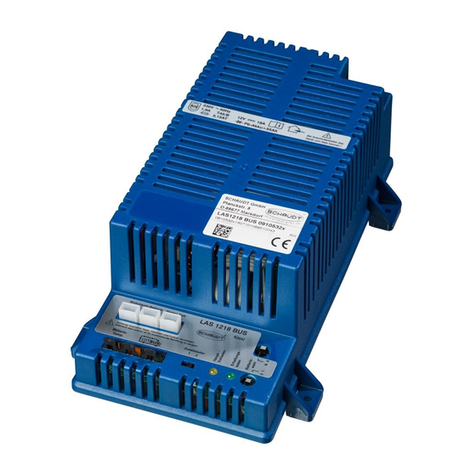
Fig. 1 LAS 1218-2 battery charger
1 Living area and start battery connectors
2 Battery selector switch
3 Indicator lamps for charging cycle
4 Installation feet
5 Mains cable with earthing type plug or WAGO
®
-connector (optional)
Y
This device is not intended to be used by persons (including children)
with limited physical, sensory or mental aptitude or lack of experience
and/or knowledge unless they are supervised by a person responsible for
their safety or have received instruction from this person as to how the
device is used.
Y
Children are to be supervised so as to ensure they do not play with the
device.
Y
This device is intended for installation into a vehicle.

Instruction Manual and Installation Instructions LAS 1218-2
4
Date: 06.11.2014 810.523 BA / EN
The LAS 1218-2 battery charger is for charging suitable batteries during
230V operation or supplying 12V consumers without connected battery with
power.
The device is a primary controlled switch-mode power supply unit. This mo-
dern switching technology achieves high charging performance at a compact
size and low weight.
The battery charger can be used:
F
as a battery charger for charging the living area battery and for re-
charging a connected starter battery
F
as an additional charger for charging the living area batteries having a
higher capacity which match every Schaudt electroblock with a type
LAS charger module
F
as a power supply unit (up to 18 A) for the 12V consumers connected.
No battery is required here.
1.3 Operation
1.3.1 Controls and indicator lamps
The device has no controls which need to be used on a day-to-day basis.
The battery selector switch need only be set correctly on initial use and for a
change of battery.
Y
DANGER!
Risk of explosion!
F
An incorrect battery selector switch setting poses a risk of explosion
due to the formation of electrolytic gases.
Y
ATTENTION!
F
An incorrectly set battery selector switch damages the living area bat-
tery.
F
Disconnect the battery charger from the mains before adjusting the
battery selector switch.
³Batteries may only be replaced by qualified personnel.
³Follow the battery manufacturer’s instructions.
³Charging unsuitable types of battery may damage them beyond repair.
It is possible to swap lead acid batteries for lead gel batteries.
Given the lack of ventilation options within the vehicle, changing from lead
gel to lead acid batteries is not possible without additional overhead.
Ask your dealer for advice.
The switching option provided by the battery selector switch ensures opti-
mum charging of the two battery types, lead gel and lead acid. The switch
must be set to the correct battery type -- lead acid or lead gel.
Battery selector switch
Changing the battery

Instruction Manual and Installation Instructions LAS 1218-2
5
Date: 06.11.2014
810.523 BA / EN
Use a thin object (e.-g.- a ballpoint pen cartridge) to move the battery selec-
tor switch.
Y
Suitability must be checked on a case-by-case using specifications from
the battery supplier and the charging parameters of Schaudt equipment.
The charging parameters are specified in the operating and installation
instructions.
³Setting lead gel battery: Set the battery selector switch to ”Lead-gel”.
³Setting lead acid battery: Set the battery selector switch to ”Lead-acid”.
³If the battery charger is used to supply 12V consumers without connec-
ted battery with power, the battery selector switch must be set to ”Lead-
acid”.
The indicator lamps on the front of the battery charger show the current
charging phase.
This indicator lamp lights up yellow in the ”Hauptladen” (Main charge) phase.
This indicator lamp lights up yellow in the ”Vollladen” (Full charge) phase.
This indicator lamp lights up green in the ”Erhaltungsladen” (Trickle charge)
phase.
Y
If the batteries are totally discharged, indicator lamp ”Erhaltungsladen”
(Trickle charge) or ”Volladen” (Full charge) may light up for a while before
the main charging phase begins.
1.3.2 System faults
A fault in the power supply system is usually caused by a blown fuse.
Please contact our customer service department if you are unable to rectify
the fault using the following table.
If this is not possible, e.g. if you are abroad, you can have the battery char-
ger repaired at a specialist workshop. Please note that the warranty beco-
mes void if incorrect repair work is carried out. Schaudt GmbH cannot ac-
cept liability for any damages resulting from such repairs.
Main charge
Full charge
Trickle charge
Flat vehicle fuses

Instruction Manual and Installation Instructions LAS 1218-2
6
Date: 06.11.2014 810.523 BA / EN
Fault Possible cause Remedy
Living area battery is not
charged during 230V
o
p
e
r
a
t
i
o
n
(
b
a
t
t
e
r
y
v
o
l
t
a
g
e
No mains voltage Switch on the circuit
breaker in the vehicle
operation (battery voltage
continuously less than
13.3V)
Have the mains voltage
checked
Battery charger is
defective
Contact the customer
service department
Battery charger fuse or
wiring is defective
Check the fuse and wiring
Living area battery is
overcharged during 230V
operation (battery voltage
continuously greater than
14.5V)
Battery charger is
defective
Contact the customer
service department
Starter battery is not
charged during 230V
o
p
e
r
a
t
i
o
n
(
b
a
t
t
e
r
y
v
o
l
t
a
g
e
No mains voltage Switch on the circuit
breaker in the vehicle
operation (battery voltage
continuously less than
13.0V)
Have the mains voltage
checked
Battery charger is
defective
Contact the customer
service department
1
2
V
p
o
w
e
r
s
u
p
p
l
y
i
n
t
h
e
D
e
f
e
c
t
i
v
e
f
u
s
e
o
r
w
i
r
i
n
g
C
h
e
c
k
t
h
e
f
u
s
e
a
n
d
w
i
r
i
n
g
12V power supply in the
l
i
i
d
t
k
De
f
ective
f
use or wiring Check the fuse and wiring
living area does not work
g
(when the battery charger
is being used as a power
supply device)
Battery charger is
defective
Contact the customer
service department
s
u
p
p
l
y
d
e
v
i
c
e
)
No mains voltage Switch on the circuit
breaker in the vehicle
Have the mains voltage
checked
The ”Volladen” (Full
charge) indicator lamp
does not light up despite
several hours of ”Main
charge” (duration
dependent on battery
type)
Defective battery Contact the customer
service department
The ”Erhaltungsladen”
(Trickle charge) indicator
l
a
m
p
d
o
e
s
n
o
t
l
i
g
h
t
u
p
Defective battery Contact the customer
service department
lamp does not light up
despite several hours of
full charge
If the battery is not
defective:
Battery charger defective
Contact the customer
service department
Y
The charging current is reduced automatically if the device becomes too
hot due to excessive ambient temperature or lack of ventilation. Always
prevent the device from overheating nevertheless.

Instruction Manual and Installation Instructions LAS 1218-2
7
Date: 06.11.2014
810.523 BA / EN
1.4 Maintenance
The battery charger is maintenance-free.
Clean the battery charger with a soft, slightly damp cloth and mild detergent.
Never use spirit, thinners or similar substances. Do not allow liquids to enter
the device.
Cleaning

Instruction Manual and Installation Instructions LAS 1218-2
8
Date: 06.11.2014 810.523 BA / EN
2 Installation instructions
2.1 Introduction
These installation instructions are aimed at trained personnel.
They contain important information on the connection and safe operation of
the device. The safety information provided must be observed.
Always follow the relevant instruction manual in addition to the installation in-
structions.
The following applications are described for the electrical connection (with
the appropriate deliverables):
F
Auxiliary charger on electroblock (section 1.1.1.1)
F
Direct connection to living area and starter battery (section 1.1.1.2)
F
Connection to additional battery (e.g. when using in conjunction with
an inverter) (section 1.1.1.3)
2.2 Mechanical installation
2.2.1 LAS 1218-2 battery charger
Y
This device is intended for installation into a vehicle.
The device was designed for floor installation.
³Install in a dry, sufficiently ventilated location. No condensation is allowed
to form on the device. To prevent a build-up of heat, ventilation holes fa-
cing the living area must be provided in the upper and lower areas of the
place of installation. Its cross-section is based on the size and average
temperature of the place of installation.
³Keep a minimum clearance to the surrounding fixtures and fittings:
F
Maintain a gap of at least 5cm on all sides (except mounted side).
F
Whilst in operation, the ambient temperature must not exceed +40 °C,
measured 2.5 cm away from the sides of the device.
³Screw the battery charger onto a firm, flat base with four screws (5mm
diameter).
Environment
Minimum clearance
Fitting

Instruction Manual and Installation Instructions LAS 1218-2
9
Date: 06.11.2014
810.523 BA / EN
134,2
147,2
118,1
80
90
163,5
247,5
Flat pins 6.3 x 0.8
in the insulation housing
4 x attachment-
holes, ø4.5
Fig. 1 Dimension diagram of LAS 1218-2 battery charger (dimensions in mm)
2.2.2 Fuse holder
For applications that require one or two additional fuses (see sections
1.1.1.2 and 1.1.1.3 for example), fuse holders from the connector set must
be installed.
³Determine the place of installation of the fuse holder(s). The place of in-
stallation must be in the direct vicinity of the corresponding battery.
³Drill a hole 8mm in diameter for every fuse holder.
³Lock the fuse holder into place in the drillhole.
2.3 Electrical connection
The battery charger connection is established in the following order:
1. All connections on the front panel of the battery charger
2. Battery lines to the battery terminals
3. 230V mains connection
Disconnect in the reverse order.
2.3.1 Connections on the front panel
Y
ATTENTION!
Short circuits!
Damage to the battery charger or fire damage to cable:
F
To protect the supply lines in the event of a short circuit, connect the
fuses directly to the positive terminal of battery.
Connection sequence
Disconnecting

Instruction Manual and Installation Instructions LAS 1218-2
10
Date: 06.11.2014 810.523 BA / EN
Select cable cross-sections in line with EN 1648-1/-2. The maximum current
load must not exceed 90% of the individual fuse rating.
Recommended cable cross-sections:
Line length*
(sum of supply and return lines)
Cable cross-section
Upto4m 2,5 mm
2
Up to 8 m (only for living area battery) 4,0 mm
2
Up to 12 m (only for living area battery) 6,0 mm
2
³Fuse the supply lines as follows:
F
with 1.5 mm
2
cable cross-section 10 A
F
with 2.5 mm
2
cable cross-section (or greater) 20 A
1.1.1.1 Connection as for auxiliary charger to the electroblock
The LAS 1218-2 battery charger can also be used as an auxiliary charger for
a Schaudt electroblock. Suitable for use here are all Schaudt electroblocks
that include the LAS charger module and have the 2-pin MN connector (e.g.
EBL 99) or Minifit connector (e.g. EBL 220) for an auxiliary charger. See the
instruction manual for the electroblock, ”Suitable accessories”.
The following parts are supplied for this application:
F
Item number 999.085 with MNL connector
F
Item number 999.161 with Minifit connector
1
2
3
Fig. 2 Connector set deliverables
Pos. Qty Name
1 1 LAS 1218-2 battery charger, earthing type plug
connection example
21* Connector cable, 1.7m with Minifit connector
31* Connector cable, 1.7m with MNL connector
* Pos. 2 and 3 as an alternative depending on electroblock to be connected
Fusing
Auxiliary charger
Deliverables

Instruction Manual and Installation Instructions LAS 1218-2
11
Date: 06.11.2014
810.523 BA / EN
The connector cable (Pos. 2 or 3) is required to connect the LAS 1218-2
battery charger to the electroblock.
An additional fuse is not required as there is already one integrated in the
electroblock. You only have to check if the fuse is fitted and if it complies
with the fuse rating on the label.
The battery charger is connected to the electroblock with a 2-pin charger ca-
ble. Other lengths are available on request.
A connection to the starter battery is not required, because the electroblock
already has the start battery recharge module.
3
45
X
X
1
2
Fig. 3 Connection Diagram of LAS 1218-2 Battery Charger -- on Electroblock
1 Flat push-on contacts, 6.3 x 0.8, red cable
2 Flat push-on contacts, 6.3 x 0.8, brown cable
3 not assigned
4 + Living area battery (red)
5 Negative battery (brown)
³2-pin charger cable: LAS 1218-2 to electroblock connection
F
+ terminal of LAS 1218-2 living area battery: Flat push-on contact, 6.3
x 0.8; (Fig.3; Pos. 1)
F
-- terminal of LAS 1218-2: Flat push-on contact, 6.3 x 0.8; (Fig.3;
Pos. 2)
F
MNL connector (view X, Fig. 3; Pos. 4/5) or Minifit connector on elec-
troblock, base ”auxiliary charger” ; see also instruction manual for
electroblock
Fusing

Instruction Manual and Installation Instructions LAS 1218-2
12
Date: 06.11.2014 810.523 BA / EN
1.1.1.2 Direct connection to living area and starter battery
For this type of connection, there is a direct connection between the
LAS 1218-2 battery charger and the two motorhome batteries (or also only
one battery, e.g. for a caravan).
The following parts are supplied under item number 999.086 for this applica-
tion:
1
234
56
7
Fig. 4 Connector set deliverables
Pos. Qty Name
1 1 LAS 1218-2 battery charger
2 7 Flat push-on contacts, 6.3 x 0.8 (blue)
3 3 Ring terminal, 1 ... 2.5 mm
2
M6
4 3 Ring terminal, 1 ... 2.5 mm
2
M8
5 2 Fuse holder for flat vehicle fuse
6 1 Flat vehicle fuse, 20A
7 1 Flat vehicle fuse, 10 A
The connector set (Pos. 2 to 6) is required to connect the LAS 1218-2 bat-
tery charger to up to two batteries.
Y
The length of the line to the starter battery may not exceed 4 m (supply
and return lines together) for a cable cross-section of 2.5mm
2
(see also
table on page 10).
Deliverables

Instruction Manual and Installation Instructions LAS 1218-2
13
Date: 06.11.2014
810.523 BA / EN
3 4
1
2
Fig. 5 Connection Diagram, LAS 1218-2 Battery Charger to Living Area and Starter Battery
1
Fuse F1
2FuseF2
3 Living area battery
4 Starter battery
³+ terminal of LAS 1218-2 living area battery (flat push-on contact 6.3 x
0.8) to F1 (flat push-on contact 6.3 x 0.8)
³F1 (flat push-on contact 6.3 x 0.8) to + terminal of living area battery (ring
terminal, M6 or M8)
³+ terminal of LAS 1218-2 starter battery (flat push-on contact 6.3 x 0.8)
to F2 (flat push-on contact 6.3 x 0.8)
³F1 (flat push-on contact 6.3 x 0.8) to + terminal of starter battery (ring
terminal, M6 or M8)
³Connection, LAS 1218-2 to living area or starter battery
F
-- terminal of LAS 1218-2 (flat push-on contact 6.3 x 0.8)
F
-- terminal of battery (ring terminal, M6 or M8)
³Label the two fuses with stickers ”F1 -- living area battery” and ”F2 -- star-
ter battery”.
Y
The negative terminal (-- Pol) of the living area battery must be connec-
ted externally to the negative terminal (-- Pol) of the starter battery.

Instruction Manual and Installation Instructions LAS 1218-2
14
Date: 06.11.2014 810.523 BA / EN
1.1.1.3 Connection to additional battery (such as when using in
conjunction with inverter)
With this type of connection, the LAS 1218-2 battery charger is used for loa-
ding an additional battery.
The following parts are supplied under item number 999.086 for this applica-
tion:
1
234
56
7
Fig. 6 Connector set deliverables
Pos. Qty Name
1 1 LAS 1218-2 battery charger
2 7 Flat push-on contacts, 6.3 x 0.8 (blue)
33* Ring terminal, 1 ... 2.5 mm
2
M6
43* Ring terminal, 1 ... 2.5 mm
2
M8
52* Fuse holder for flat vehicle fuse
6 1 Flat vehicle fuse, 20A
71* Flat vehicle fuse, 10 A
* Pos. 3 and 4 each only required 2 x, Pos. 5 only 1 x, Pos. 7 not used.
The connector set (Pos. 2 to 6) is required to connect the LAS 1218-2 bat-
tery charger to the additional battery.
The application shown in Fig. 7 is based on articles ”Connector sets for integra-
tion of an inverter” (article nos 798.023 and 999.208) available from Schaudt. In
principle, such a connection is always suitable when an addition battery is char-
ged.
Y
The length of the line to the additional battery may not exceed 4 m (sup-
ply and return lines together) for a cable cross-section of 2.5mm
2
(see
also table on page 9).
³+ terminal of LAS 1218-2 (flat push-on contact 6.3 x 0.8) to F4 (flat push-
on contact 6.3 x 0.8)
Deliverables

Instruction Manual and Installation Instructions LAS 1218-2
15
Date: 06.11.2014
810.523 BA / EN
³F4 (flat push-on contact 6.3 x 0.8) to + battery terminal (ring terminal, M6
or M8)
³LAS 1218-2 to additional battery connection
F
-- terminal of LAS 1218-2 (flat push-on contact 6.3 x 0.8)
F
-- terminal of battery (ring terminal, M6 or M8)
³Label the additional fuse with sticker ”F4 -- additional battery”.
+--
230 V
G
B
D+
EBL ...
DT ... /
LT ...
LAS 1218-2
230 V
12 V
+--
G1
G2
G3
12 V
LRS
F1
F2
F3
F4 DC/AC
230 V
K1
Fa
Fb
Shunt
+--
+--
Fig. 7 Example circuit diagram, inverter installation
(grey background: LAS 1218-2 battery charger with connector set)
Pos. Name Pos. Name
DC/AC Inverter F4 Fuse, additional battery charge current
DT.../LT... DT ... or LT ... control and display pa-
nel in the vehicle
GVehicle alternator (higher rating)
EBL ... Electroblock G1 Starter battery
Fa Fuse, EBL ... charge current for starter
battery
G2 Living area battery
Fb Fuse, EBL ... charge current for living
area battery
G3 Additional battery
F1 Fuse, starter battery -- cut-off relay K1 Cut-off relay, starter battery -- additio-
nal battery
F2 Fuse, cut-off relay -- additional battery LAS 1218-2 Battery charger
F3 Fuse, inverter supply LAS Charger module of electroblock

Instruction Manual and Installation Instructions LAS 1218-2
16
Date: 06.11.2014 810.523 BA / EN
2.3.2 Mains connection
Y
DANGER!
230V mains voltage carrying parts.
Danger of death due to electric shock or fire:
F
Only carry out electrical work once the 230V supply has been discon-
nected.
³The mains must be connected as follows:
F
to a insulated distribution unit with protective contact
F
to a socket with protective contact (isolated ground or suitable plug
connector from WAGO
®
, depending on LAS 1218-2 variant).
The power cord must be of type H05VV-F 3x1.5.
³The mains cable must have a strain relief where required.
2.4 Initial use
2.4.1 Checks prior to initial use
³Ensure that the batteries are connected properly (only for initial use, ope-
ration without battery is possible in general).
2.4.2 Setting battery type
³Establish battery type.
Y
DANGER!
Incorrect setting of the battery selector switch.
Risk of explosion from build-up of electrolytic gas, defective battery, defec-
tive battery charger or as a result of too high a battery operating tempera-
ture (above 30 °C):
F
Move the battery selector switch to the correct position.
F
The battery charger is to be used solely for connecting to the 12V
power supply with rechargeable 6-cell lead-gel or lead-acid batteries.
Do not use any unsuitable battery types.
³Store batteries in a place with adequate ventilation (or provide integrated
ventilation). Follow the instructions provided by the battery manufacturer.
lead-gellead-acid
Fig. 8 Battery selector switch lead-gel-/lead-acid battery.
Mains connection
Before starting up

Instruction Manual and Installation Instructions LAS 1218-2
17
Date: 06.11.2014
810.523 BA / EN
³Disconnect the battery charger from the mains before moving the battery
selector switch.
³Move the battery selector switch (see Fig. 8) into the correct position
using a thin object, such as a ballpoint pen:
F
Lead gel battery: Move the battery selector switch to ”Lead-gel”.
F
Lead acid battery: Set the battery selector switch to ”Lead-acid”.
³Re-check that the battery selector switch is set correctly for the type of
battery used.
Y
Suitability must be checked on a case-by-case using specifications from
the battery supplier and the charging parameters of Schaudt equipment.
The charging parameters are specified in the operating and installation
instructions.
2.4.3 Starting up the system
³Ensure that the battery is connected correctly (or all if more than one is
available).
³230V mains supply must be connected to vehicle.
³Power on the electrical system of the vehicle (e.g. power on 12V main
switch on the switch panel, see instruction manual for switch panel con-
nected).
³230-V- mains cable of the LAS 1218-2 charger must be connected (the
charger does not have its own mains switch).
³Check whether the batteries are being charged (display on the battery
charger).
2.5 Technical details
2.5.1 Mechanical details
ca. 90 x 148 x 248 (H x W x D in mm), including attachment feet
1.0 kg
Polyamide blue, similar to RAL 5010
2.5.2 Electrical details
230 V AC voltage +10%, 47 -- 63 Hz sinusoidal, protection class I
1.9 A
6-cell lead acid or lead gel batteries, 55 Ah and above
approx. 0.3 mA
Conditions for the measurement:
F
approx. 10 min after mains isolation without mains connection
F
with battery connected (battery voltage 12.6V)
12V outputs A maximum of 90% of the nominal current of the
relevant fuse may be drawn.
Dimensions
Weight
Housing
Mains connection
Current consumption
Suitable batteries
Standby current from
living area battery
Current-carrying
capacity

Instruction Manual and Installation Instructions LAS 1218-2
18
Date: 06.11.2014 810.523 BA / EN
Living area battery
Charging curve IUoU
Final charging voltage 14.3 V
Charge current 18 A in the entire mains voltage range,
electronically limited, minus the
charge current into the vehicle battery
Voltage for float charge 13.8 V with automatic switchover
New charge cycle, with battery voltage below 13.8 V
Switchover to main charging with approx. 5 seconds delay
Main charge
I
Full charge
Uo
Float charge
U
4hwithleadacid
16 h with lead gel
Time
14,3
13,8
Solar
charging
V
Fig. 9 Example of the charge voltage behaviour with the LAS 1218-2 battery charger
I Main charge with maximum 18 A charging current, electronically limi-
ted, up to final charging voltage. Start of charge also for totally dischar-
ged batteries.
Uo Automatic changeover to full charge with constant 14.3 V. The duration
of the full charge phase depends on the type of battery and is configu-
red on the device: Lead-acid batteries, 4 hour, lead-gel batteries, 16
hours.
U Automatic changeover to trickle charge with constant 13.8V. In the
trickle charge phase, the voltage at the output of the charging module
is constant. The battery is now fully, or virtually fully, charged.
Start of a new charging cycle by switching over to main charge, if the battery
voltage falls below 13.8 V for more than 5 seconds when loaded. Start of
charge also for totally discharged batteries.
For mains operation, the starter battery is also charged (with maximum
charge current of 3A). The final charge voltage is 14.1 V.
Output current 18 A, connection of a battery not required
Output voltage 14.3V/13.8V,
suitable for 12V consumers, smoothed DC voltage
2.5.3 Environmental parameters
-20 °Cto+45 °C
-20 °Cto+70°C
Operation in dry environment only
CE mark
2.6 Storage - Packaging - Transportation
Only transport and store the battery charger if the packing is suitable and
ambient conditions are dry.
No part of this manual may be reproduced, translated or copied without ex-
press written permission.
Battery charging via
mains connector
Battery charging of the
starter battery
Operation as
power supply unit
Operating temperature
Storage temperature
Humidity
CE
E

Instruction Manual and Installation Instructions LAS 1218-2
19
Date: 06.11.2014
810.523 BA / EN
Appendix
A EC Declaration of Conformity
Schaudt GmbH hereby confirms that the design of the LAS 1218-2 battery
charger complies with the following relevant regulations:
F
EC-Low Voltage Directive: 73/23/EEC edition with modifica-
tions
from 22.07.93
F
Directive on Electromagnetic 89/336/EEC with modification
Compatibility 92/31/EEC
F
Norms and technical specifications applied, in particular:
-- DIN EN 60335-1: 1994 + A11 + A1 + A12 + A13 + A14
-- DIN EN 60335-2-29: 1996 + A11
-- DIN EN 50081-1: 3.1993
-- DIN EN 50082-1: 3.1993
-- DIN EN 61000-3-2: 2000
The original EC Declaration of Conformity is available for reference at any
time.
Schaudt GmbH, Elektrotechnik & Apparatebau
Planckstraße 8
88677 Markdorf
Germany
B Accessories
Suitable connector cable (MNL or Minifit) to Schaudt eletroblock.
Connector set with fuse holders and connector material
C Customer service
Schaudt GmbH, Elektrotechnik & Apparatebau
Planckstraße 8
D-88677 Markdorf
tel.: +49 7544 9577-16 email: kundendienst@schaudt-gmbh.de
Office hours Mon to Thurs 08.00 -- 12.00, 13.00 -- 16.00
Fri 08.00 -- 12.00
Returning a defective device:
³Fill in and enclose the fault report, see Appendix D.
³Send it to the addressee (free of charge).
Manufacturer
Address
Additional charger
As a standalone device
Customer service
address
Send in the device

Instruction Manual and Installation Instructions LAS 1218-2
20
Date: 06.11.2014 810.523 BA / EN
D Fault report
In the event of damage, please return the defective device together with the
completed fault report to the manufacturer.
Device type: _______________________
Item no.: _______________________
Vehicle: Manufacturer: _______________________
Model: _______________________
Own installation? Yes -No -
Upgrade? Yes -No -
Following fault has occurred (please tick):
-Electrical consumers do not work -- which?
(please specify below)
-Switching on and off not possible
-Persistent fault
-Intermittent fault/loose contact
Other remarks:
Other manuals for LAS 1218-2
1
Table of contents
Other Schaudt Batteries Charger manuals
Popular Batteries Charger manuals by other brands
Sterling Power Products
Sterling Power Products Pro Charge Ultra Installation instructions manual
DIC
DIC 711 Mounting and operating instructions

PowerBase
PowerBase 620674 instruction manual
Nikon
Nikon MH-62 instruction manual

Dynamite
Dynamite Prophet P1 Mini instruction manual
Jarv
Jarv JRV-DTC3000 user guide
