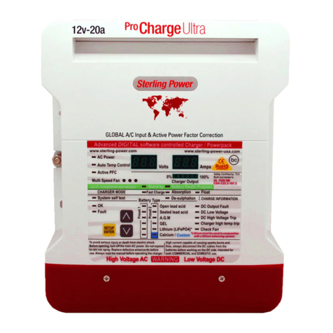
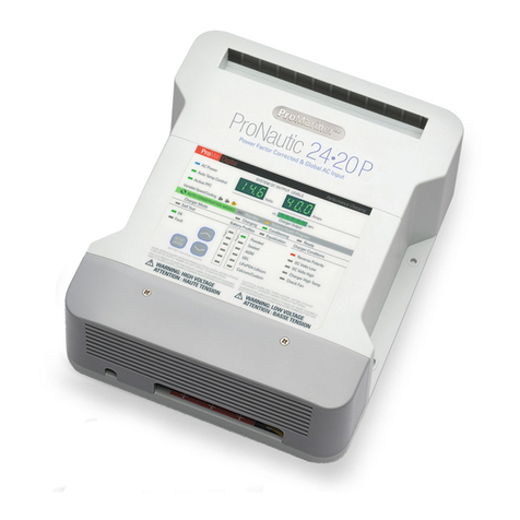
Sterling Power USA Pro Charge Ultra Lite User manual

Pos
in
STERLI G
POWER
Reading this paragraph should be sufficient for 90% of
installers. Connect the Bat 1 and Bat 2 DC outputs to
the respective battery banks, use an appropriate fuse
(40A fuse). Then wire up the negatives (all should be
common). All DC cables should be at least AWG 10-8
(6-10 mmSq). Wire a plug to the AC Live|Earth|Neutral
cable and plug it to a 80V-270VAC (40Hz-70Hz) AC
supply. The charger should turn on and begin charging
both Bank 1 and Bank 2 at the default charging profile
of a sealed lead acid battery (14.4V abs. and 13.6V
float). This profile shall be adequate for most batteries
(please ensure). The charger does not need to be
turned off.
If users wish to install the temperature sensor for a
more accurate seasonal charging rate and for battery
temperature warnings then install onto the negative
terminal of the bank you wish to sensor (typically the
House / Service bank - as depicted).
Basic Installation
fuse fuse
Live
Earth
Neutral
AC input
80V-270VAC
40Hz-70Hz
AC input
(pre-wired cable)
Bank 1
(starter)
Bank 2
(House / Service)
Pro Charge Ultra Lite
30A AC to DC Battery Charger
USER’S MANUAL.
All negatives
are common
Copyright © 2017 Sterling Power V 2.6 August 2017
RoHS
compliant
Features
- Global Voltage 80-270V AC 40-70 Hz
- 6 stage progressive Battery Charger.
- Extremely efficient, up to 90%.
- Synchronised rectification.
- Fully Active PFC.
- Custom Battery Charge Selection + 8 presets.
- 2 isolated outputs.
- 18 LED front panel for user information.
- Perfect for generator use.
- Night time settings to reduce fan noise.
- Power pack mode - does not require a 12V battery to provide power.
- Daisy chain enabled (optional), temp sensors linked across multiple
batteries.
If one of the batteries exceeds 50/60/70 DegC the unit shall trip.
Sterling Power Products
H Charge Float
In / Unit Out / Rem
Batt.
V12.2
Temp
Menu
Change
Volts
Select
Audible alarm on/off
hold > 3 sec
On / Off
hold>3 sec
Fault
Absorption
Cond.
Optional parts available for this product
1) Analogue battery temperature monitor / trip with
10m off cable. TSAY
2) Digital temperature trip, can be daisy chained and
available in various temperatures. TSD50 TSD60 TSD70
3) Remote control unit. LPCUR 13
2
optional extra

Sterling Power Products
Copyright
STERLI G
POWER
Contents Page
Product Specifications
The Pro Charge Ultra Lite (LPCU1230) is an AC to DC battery charger
designed to charge up to 2 battery banks at a charging current of 30A.
Standards
Tested to CE standards
EN61000-3-2
EN61000-3-3
EN55014-1
EN 55014-2
EN60335-2-29
EN ISO 13297
EN 6100-3-2 Class
LPCU1230
Input Voltage (V AC) 80 - 270
Input Frequency (Hz) 40 - 70
Efficiency 94.40%
Total Harmonic Distortion 2.4% voltage
Total Harmonic Distortion 2.4% current
Ripple noise (rms) 12mV
Ground Leakage 0.5 mA
Voltmeter accuracy 1%(+/-)
IP rating IP21
Ignition Protected Yes
Quiescent Current (W) 1
Weight (Kg) 1.5
Dimensions (LxWxD) mm 190 x 160 x 50
Generator / main power (W) 500W
Page 3 - Legal and Safety.
Page 4 - Front Panel and Dimensions.
Page 5 - Installation Diagram / procedure.
Page 6 - Features and Force Options.
Page 7 - Battery Type / Chemistry Select.
Page 8 - Customising Battery Type.
Page 9 - Other features | BMS trip | Temp sensor | Daisy chain.
Page 10 - Fault finding
Page 11 - Remote Control Features
Page 12 - Customer Service & Warranty
Fill with more product specs
2

Using the Instruction Manual
This manual must be read throughout before installing
this electronic device. Do not lose these instructions -
keep them safe. The most up to date instructions can
be found on the Sterling Power website. Please refer to
the latest instruction manual before contacting Sterling.
At Sterling, we endeavour to include all of the product
information that we can think of into the manual.
Installation of the electronic device must be carried out
by a qualified and trained personnel only. The
personnel must be familiar with the locally accepted
guidelines and safety measures.
Sterling Power’s warranty statement
A comprehensive warranty statement is provide at the
back of the instruction manual. A comprehensive
warranty statement can also be found on sterling-
power.com.
Copyright and plagiarism
Copyright © 2016 Sterling Power. All rights reserved.
Reproduction, transfer, distribution or storage of part or
all of the contents of this document is strictly prohibited.
If you wish to use all of this document, or excerpts from
it, Sterling Power must be contacted.
Liability
Sterling Power can not accept liability for:
Ÿconsequential damage due to use of this device
Ÿpossible errors in the manuals and the results
thereof
Device modification
Please do not modify the device unless you have been
instructed to do so by Sterling Power, directly. Product
modification shall be done at Sterling, when needed.
Warranty shall be voided if personal attempts are made
to modify the device, without Sterling’s approval.
Use the battery charger only:
ŸFor AC to DC conversion.
ŸFor DC charging limiting.
ŸWith fuses protecting the DC cables.
ŸIn a well ventilated, dry, dust-free and condensation
free environment.
ŸWhen instruction manual has been read through.
Safety Symbols
ŸExample - WARNING. Never use the device in
situations where there is danger of gas / dust
EXPLOSION or potentially flammable products.
General maintenance and repair
The device must be switched off during maintenance. It
must also be protected against unexpected switching
off. Remove battery connections and ensure unit is off.
If repair is required, only use original parts.
General safety and installation precautions
ŸInstall device in well ventilated space. Do not
expose device to: Rain, snow, spray, moisture,
pollution, condensation. Do not cover or obstruct
ventilation openings.
ŸDevice connects to common negative. Common
negative must be earthed.
ŸIn case of fire use a fire extinguisher.
ŸEnsure reverse polarity and short circuiting is
avoided - to prevent damage to battery.
ŸProtect DC wires with the appropriate sized fuse.
ŸCheck cabling annually- fix where needed.
ŸAvoid contact with device with damp hands.
ŸEnsure the device is adequately and securely
mounted to prevent the unit from displacement.
ŸUse a professional to install device.
Battery safety
Excessive charge or discharge and high voltages can
cause serious damage to batteries. Never exceed the
recommended limits. If battery acid contacts skin or
clothing, wash immediately with soap and water. If acid
enters the eye(s), immediately flood the eye(s) with
running cold water for 20 minutes and seek medical
attention.
Give extra care to not drop metal tools or jewellery on to
the battery terminals as short circuiting can take place.
Refrain from charging battery up to 4 hours prior of
installation to avoid the formation of explosive gases.
Never smoke / generate a spark around batteries.
CAUTION
WARNING
EXPLOSION
Legal and Safety
3

96
10
11
13
8754
3
2
1
12
14
15
16
17
18
19
20
21
22
23
24
25
26
27
1) Remote control socket
2) Battery temperature sensor connector
3) Daisy chain link for multiple temp sensors
4) Positive DC battery outputs 1 & 2
5) SELECT function button B
6) Fuse 40A
7) Enter / select function button A
8) BMS 1 and 2 port or remote shut down
9) Negative DC
10) Secondary high voltage trip, critical fault.
11-18) Information LEDs
- On start up they show chosen battery type.
- After 30s these shall display DC output
voltage.
- Also used during the custom voltage setup.
19) Solid - Night Mode, 8 hours at half power +
reduced fan speed.
Flashing - reduced power.
20) Solid - High unit temp. trip.
Flashing - High battery temp trip.
21) Temp sense is fitted (solid) all okay.
22) Solid - daisy chain trip LED
High DC Voltage trip LED (1 flash)
BMS trip LED (2 flash)
23) Solid - Float mode.
Flash - Energy saving.
24) Conditioning mode.
25) Absorption mode.
26) Fast Charge / Bulk.
27) Unit active power to internal electronics.
Front Panel
4.60
73.00
4.60
158.00
198.51
43.13
158.00
5.50
10.60
4.60
112.13
4.00
199mm(H)
158mm(W)
70mm(D)
Pro Charge Ultra Lite Dimensions
units in millimetres (mm)
Refer to Page 10 for more information
regarding these LEDs and for fault finding.
NOT TO SCALE
4

Sterling Power Products
Copyright
Pos
in
Installation Diagram
AC input
80V-270VAC
40Hz-70Hz
AC input
(pre-wired cable)
+
_
12V starter bank +
_
12V domestic bank
DC fuse
40A fuse
DC fuse
40A fuse
+
_
12V domestic bank
AC circuit breaker
Ensure you read the Legal and Safety before
installation. We recommend hiring a professional
to fit this charger. Above is a wiring guide.
Mount vertically in a well ventilated, dry
environment.
1) Connect DC cable to the negative (black) and
the positive Bat 1 / Bat 2 output (red).
2) Then connect the negative to the common
negative of the DC system.
3) Then connect the positive outputs via the
relevant fuse to the battery banks.
4) (Temp sensor optional) connect the exposed
wire end of the temperature sensor to the Batt
Temp Sen. port on the circuit board (as depicted
by the grey wire). Connect the yellow sensor to
the negative terminal of the battery you wish to
sense (typically the domestic / house bank).
5) Connect remote (optional) to the remote port.
6) Finally, connect the AC lead cable to NON-live
mains / circuit breaker. Ensure 80V-270VAC (40-
70Hz). Shall also run from 130VDC - 320VDC.
7) When AC is live, charger should turn on.
Ground / bonding / earthing points:
1) The earth wire (AC input, the ground).
2) The chassis / bonding ground (going to a vehicle
body / boats bonding system).
3) The DC negative.
In most installations all these will end up at the same
point. The AC power source should be connect to the
boat/vehicle chassis (for safety). The chassis earth will
also go there and the DC negative should also go
there. In effect, bonding the total system together
ensuring any fault to the chassis will blow a fuse. This
could vary for steel/aluminium boats.
Installation Procedure
Fuses and Cabling
Grounding / Earthing
Model
110VAC
Cable
Breaker
Rating
230VAC
Cable
Breaker
Rating
LPCU12302
3 Core
1.5mm2
11A
3 Core
1.5mm2
7A
AC installation - use ring or captive spade connections
and a proper crimping tool to attached AC cables to the
breaker. Support the cable every 50cm and protect from
sharp edges when passing through bulkheads. The table
below is rating for cabling up to 15m.
DC installation - each of the positive outputs from the
charger must be fused. Place fuse approximately 18cm
(ABYC standard) from the +ve terminal of the designated
battery. Rate fuse to 20% higher than charger amp rating.
Fuse protects your cabling, not the charger.
Model
1m DC
Cable
3m DC
Cable
5m DC
Cable
Fuse
LPCU12302
AWG10
5mm2
AWG8
8mm2
AWG6
14mm2
40A
Battery Temp Sensor
connect to negative
of domestic bank
DC of 130-320VDC
1
2
BMS
off
Drawing shows twin battery bank installation. For single
bank, simply use one output. Both outputs are capable
of carrying the full current, albeit, not simultaneously.
remove the red end cap at the bottom
of the PCU Lite to reveal the circuit
board:
For BMS instructions refer to page 9
For Daisy Chain refer to
page 9
5

20+
30+
Toggle 1/2 and 1/1 (full) power
Energy saving mode 1 (not Lithium)
A BUTTON
Force to 1/2 power
This will reduce the units power by about 50% and reduce
noise. Hold A button only for 5-9 seconds. To confirm, the
half power LED shall flash 5 times. 1/2 power remains
indefinitely. To return to full power, press the setup button
again, for 5-9 seconds.
Force to Float modes
Float - mode 1.
Hold both buttons down for 2-10 seconds and let go. This
shall put the charger into float. The charger shall now
remain in float UNTIL the charger is restarted (off and on).
The charger shall then revert back bulk/abs.
Float - mode 2.
Hold both buttons down for 20-30 seconds and let go. This
shall lock the charger into float, indefinitely. If the charger is
restarted the charger shall go into float mode and remain
there.
To get out of these modes, repeat the procedures.
Energy saving mode 2 (not Lithium)
Energy saving modes
What is Energy Saving?
Energy Saving puts the charger’s DC output to that of
a charged battery:
ŸGel I, Gel II, AGM I and AGM II = 12.8V.
ŸSealed lead acid and open lead acid = 12.6V.
ŸCalcium = 12.7V.
ŸLiFePO4 = 13.4V.
The charger shall not go above this voltage and shall
be a power supply if the voltage drops below. This is
an attempt to make sure the batteries are kept
topped up, yet, preserves AC power. Allows for
utilization of renewable energy charging, like solar or
wind and takes the burden off the charger.
Mode 1
Hold A button down for 10-19 seconds. The charger
will enter ‘Energy Saving’ mode for the duration of the
charger being turned on. Once the charger is turned
off and on again the charger reverts back to
bulk/absorption voltages.
Mode 2
Hold A button down for 20-29 seconds. The charger
will enter ‘Energy Saving’ mode indefinitely. If the
charger is turned off and on again the charger
remains at 12.8V.
Force to Night Mode
This will reduce the unit’s power by around 50% for about 8
hours and reduce fan noise. Hold B only for 5-9 seconds.
The Night Mode LED shall come on solid. Please note that
night mode has to be set every single time you wish to use it.
It can NOT be set to come on at a certain time daily. Repeat
procedure
Battery type select
See overleaf.
Features and Force Options
Both the Enter (A) and Select (B) buttons are required
when modifying the force options on the Pro Charge
Ultra Lite. The ‘Night mode’ LED shall flash every 1
seconds to denote the pressing of Button A. The
‘12.4V Custom’ LED shall flash every 1 second to
denote the pressing of Button B. Night mode (s) 12.4 V Custom
A B
A B
A
B
A B
A
A
Action
Press Length
(seconds)
5 - 10
10 - 20
20+
Press to display battery type
Night Mode - 1/2 power for 8Hrs
B BUTTON
Display software version
B
Action
Press Length
(seconds)
<1
5 - 10
10+
A + B BUTTON
Action
Force unit to float (mode 1)
Battery type select
Force unit to float (mode 2)
Reset unit to default
6

Battery Chemistry Chart
Bulk / Abs. Cond. Float Min | Abs. | Max
Volts
14.00
14.10
14.40
14.40
14.60
14.80
15.10
15.50
14.40
Custom Charging Profile
Volts
13.70
13.40
13.60
13.80
13.70
13.30
13.60
--------
13.80
Mins
60
60
120
720
60
60
60
240
30
Mins
600
480
480
1440
480
480
360
240
30
Volts
13.85
13.75
14.15
14.00
14.10
14.00
14.30
--------
13.80
Options
1) Gel I
2) AGM I
3) Sealed
4) Gel II
5) AGM II
6) Open
7) Calcium
8) De-sulph.
9) LiFePO4*
10) Custom
If battery temperature sensor is connected then all
voltages are based on 20DegC. If sensor senses less
than 20DegC = increased voltage. Higher than 20DegC
= decrease voltage. The further from 20DegC in either
direction leads to proportional increase or decrease in
the voltage (x2 for 24V | x3 for 36V | x4 for 48V).
Remember it is the voltages that are more important
than our battery types. After installation, test the voltage
from the unit is the desired voltage. Ensure you
remove at least 1 wire from the battery temperature
sensor as the product voltage may be higher ( if in
cold climate ) or lower ( if in warm climate ) than the
preconceived voltage. The voltage requirements of
the battery company will override our recommendations
as it is them who are supporting the battery warranty.
*Lithium profile has reverse polarity protection
disabled. **All voltages shall be 0.1V higher for
the first 3 minutes of the chargers operation.
Adjusting Battery Chemistry
Changing charging profile during startup.
While the unit is running, simply hold down the A and B
buttons for 10-20 seconds and let go. All LEDs on the
column shall now flash. The Sealed LED (yellow) shall
come on solid. Press the B button to go up the column
and the A button takes you down the column. The LED
shall light up demonstrating which profile you have
selected. When the LED has illuminated at your
desired profile simply hold both buttons for a couple of
seconds or simply just leave the charger alone for 30
seconds and it will change. The chosen profile LED
shall then flash. The unit shall then restart and go
through the starting cycle again.
N.B. if you wish to select Gel II or AGM II the respective
LEDs shall flash.
Default profile
LiFePO4
Desulphation
Calcium
Open / Flood
AGM / AGM II(fl)
GEL / GEL II (fl)
Sealed
Custom
Secondary high....
A B
7
Return to Factory Defaults
If you have made a mistake or your charger is behaving in a way that you were not expecting, please put
your charger through a factory reset.
Return to factory default: This shall irreversibly erase all previously entered settings. Press and hold
both buttons for 30 seconds+ and let go. The LED columns shall alternatively flash. To confirm factory
default press BOTH buttons again for 2 seconds. Once confirmed, 4 green LEDs on the left flash. The unit
should then reboot with the default settings. To reject factory default settings, simply let the LED columns
continue alternatively flashing.
A B

Sterling Power Products
Copyright
What can be customized?
1) Boost / bulk / absorption (V) ______
2) Conditioning (V) ______
3) Float (V) ______
4) Absorption Time Factor (0-14) ______
5) Absorption Minimum (0-720 minutes) ______
6) Absorption Maximum (0-720 minutes) ______
Opportunity to adjust Fast Charge / Bulk /
Absorption voltage.
Yellow Absorption LED will flash (section 2 on graph).
Adjust Fast Charge voltage by using the A and B
buttons to go up and down the voltage LED column to
select the correct Fast Charge voltage. Once content,
wait 30 seconds, or press both buttons to confirm. The
unit shall then proceed to Conditioning charge voltage
(next below).
Opportunity to adjust Conditioning charge
voltage
Green Conditioning LED will flash (section 2 on
graph). Likewise, adjust the conditioning voltage by
using the A and B buttons to go up and down the right
LED column to select the correct Conditioning
voltage. Once content, wait 30 seconds, or press both
buttons to confirm. The unit shall then proceed to float
voltage set (next below).
Opportunity to adjust float charge voltage
Blue Float LED will flash. Likewise, adjust the float
voltage by using the A and B buttons to go up and
down the LED column to select the correct Float
voltage. Once content, wait 30 seconds, or press both
buttons to confirm. The unit shall then proceed to float
voltage set (next below).
Opportunity to adjust absorption time factor
Blue Float LED continues flashing. This time, adjust
the time factor by using the A and B buttons to go up
and down the LED column (refer to the 0-blue scale
14) to select the correct time. Once content, wait 30
seconds, or press both buttons to confirm. The unit
shall then proceed to minimum absorption time factor
(next below).
Opportunity to adjust minimum absorption time.
Blue Float LED continues flashing. This time, adjust
the minimum absorption time by using the A and B
buttons to go up and down the LED column (refer to
the orange scale) to select the correct time. Once
content, wait 30 seconds, or press both buttons to
confirm. The unit shall then proceed to maximum
absorption time (next below).
Opportunity to adjust minimum absorption time.
Blue Float LED ing. This time, adjust continues flash
the maximum absorption time by using the A and B
buttons to go up and down the LED column (refer to
the orange scale) to select the correct time. Once
content, wait 30 seconds, or press both buttons to
confirm.
Customising Battery Chemistry
A B
8
Setting Boost/Cond./Float voltages.
Set voltages by using this column of LEDs.
The respective LED(s) shall illuminate to
denote the voltage you have chosen. If you
want a voltage in between then both LEDs,
either side, shall illuminate. To select 14.2V,
for example, both the 14.0V LED and 14.4V
LED shall come on solid. If you want 14.1V,
then the 14.0V LED shall come on solid and
the 14.4V LED shall flash.
Setting Absorption Time Factor (ATF).
ATF is simply a number (0-14) that can be used
to multiply by the length of time the charger
takes to reach the bulk/boost voltage from
start. For example, if the bulk voltage is
reached in 10 minutes with the ATF at 4, then
10mins x (ATF 4) = 40 mins of absorption. Like
above, if you need a number in between both
LEDs, either side shall illuminate solid.
Setting Min/Max absorptions times (mins)
Use this column of LEDs to pick the minimum
and maximum absorption times. There is no in
between selections, simply what is ascribed. If
there is a contradiction with the absorption
time factor (ATF) then the ATF value takes
precedence. If ATF is set to 0 and you have set
a minimum absorption time of 30 mins - 0 mins
shall be the absorption time.
Operating procedure
Press and hold both A and B buttons for 10-20
seconds.
Press the A or B buttons to move LED down to
custom (Yellow LED). Hold both buttons for 2
seconds to confirm. Now refer to the column of text to
the right hand side --->
The bottom column of LEDs have multiple functions in
the customising procedure, here is a breakdown:

+
_
12V domestic bank
Other features
Battery Management System (BMS) - for lithium battery users.
Remote Trip - for any users.
Only use one of these 2 ports, do not use both.
1
2
BMS
Use BMS 2 - if your BMS trips to a +ve voltage (2V-17V), then use
BMS 2. This shall result in the PCUL turning off when this voltage is
received. Once the BMS removes this trip status, i.e. the +ve signal
goes back to 0V signal, the PCUL shall start charging again. The
time delay is 30 seconds.
BMS 1
status:
operational: 2-17V
trip voltage: 0V
BMS 2
status:
operational: 0V
trip voltage: 2V-17V
or
Use BMS 1 - if your BMS trips and provides a 0V (ground signal), then
use BMS 1. This shall result in the BBC turning off. Once the BMS
removes this trip status, i.e. the 0V signal goes back to a +ve signal,
the PCUL shall start charging again. The time delay is 30 seconds.
Remote trip - the BMS connector can also be used as a basic remote trip. Simply apply the
correct trip signal voltage to the relevant BMS connector for the desired effect.
Connect the temperature sensor
(TSAY) to the negative terminal of
the battery bank. It is imperative
that the sensor is put on the
negative terminal.
The temp sensor has two
cables at the end. Place one
in each of the two connectors.
The polarity does not matter.
The Daisy chain link should
come with a bridging link, as
depicted. If you have no use
for this feature, leave this link
in place.
If this link is removed, the
charger shall stop. Reconnect
the link and turn off charger at
the mains and turn on again to
resume charging.
Wiring example for daisy chain with the PCU Lite.
Starter Battery
Domestic battery
generic busbar
TSD60 is the Sterling part
number of the 60Deg trip
temp. sensor.
Wire up all of the temp.
sensors in series with each
other. A busbar is shown to
make it look neater, albeit
not necessary.
TSD60
TSD60
Install TSD onto negative
terminal of battery.
Daisy Chain Link
Temperature Sensor
Battery Management System (BMS) / or simple Remote Trip
If a temp. sensor trips the circuit the charger shall turn off immediately. It shall
have to be turned off at the mains and turned on again to resume charge.
The PCU Lite shall trip if the temperature sensor reads
56 Deg C or over. The charger shall have to be turned
off at the mains and turned on again to resume charge.
9

Fault Finding
96
10
11
13
8754
3
2
1
12
14
15
16
17
18
19
20
21
22
23
24
25
26
27
8) BMS 1 and 2 port - ensure you do not have connections to both ports. Only use one port or no ports. BMS1 must
be connected to a signal that goes to ground (0V) under trip conditions. BMS2 must be connected to a signal with a
positive voltage (2-19V) under trip conditions.
9) Negative DC - ensure your negatives are common throughout your DC circuitry.
10) Secondary high voltage trip, critical fault. Worth calling Sterling Power.
19) Power reduce. % (fl) - table:
The charger’s power output
reduces based on internal
temperature. If your charger
is not putting out full power
then refer to this table.
20) Solid - High unit temp. trip. The charger’s temperature has reached 96DegC+. The ambient temperature is too
high for the PCUL to operate. Turn off at mains, move to cooler environment, turn on.
High Batt. Temp (fl). This LED shall only be flashing if you have the temp sensor connected to port 2. If your battery’s
temperature has exceed 55DegC then this LED shall flash.
22) Solid LED - daisy chain trip LED - check the daisy chain link connector - you either have a trip signal from your
daisy chain or the link connector has fallen out.
1 x Flash LED - High Voltage trip - The DC voltage across the battery has exceeded 16V. You may have solar power
- it is worth getting a solar regulator to bring this voltage down.
2 x Flash LED - BMS trip - if you have a BMS trip cable going to the BMS connector the signal has tripped the
charger. Wait for the BMS trip signal to go. BMS connector can also be use as a signal trip to an on/off style switch,
ensure this switch is in the correct position.
Temperature (DegC) Power Reduction LED flashes
75 -20% 1
80 -30% 2
85 -50% 3
88 -75% 4
90 -90% 5
1) Remote control socket - if the remote
control is not working properly, check for
loose connection at this port.
2) Battery temperature sensor connector -
the temperature sensor (Sterling part number
TSAY) has two wires, one wire must go into
one of connector and the other wire into the
remaining connect. Polarity does not matter.
3) Daisy chain link - ensure there is a bridge
between these two slots. If there is no bridge
connector, the PCUL shall not charge. If you
have reconnected the bridge connection -
you will need to turn off charger + on again.
4) Positive DC battery outputs 1 & 2 - ensure
you have battery voltage at both of these
terminals. If you have 0V then your batteries
are either not connected or you have
continuity issues between PCUL and battery.
If you are using on one output, please link the
other output up to it.
6) Fuse - 40A fuse. If blown, please replace.
Ensure good contact between fuse and fuse
holder.
The primary test the user can do before calling Sterling is to check
what your AC input voltage is going into the PCUL. Ensure it is
between 80-270VAC. Do the LEDs on the PCUL display then come
on? If they do, then measure the DC voltage across the negative and
positive terminals of the PCUL. If you are getting battery voltage (10-
12V) then check the PCUL has not been turned off or put into energy
saving mode (check page 6). If you are getting 0V here, please
check you have got continuity between the batteries and the
charger. Possible fuse blown, possible poor contact, loose cable etc.
10

Sterling Power Products
Copyright
Sterling Power Products
H Charge Float
In / Unit Out / Rem
Batt.
V12.2
Temp
Menu
Change
Volts
Select
Audible alarm on/off
hold > 3 sec
On / Off
hold>3 sec
Fault
Absorption
Cond.
6
7
5
1
2
3
4
8
9
Volts Select Button (left)
> 4 sec. => unit standby / unit charger.
> 2 sec. => buzzer on/off
> 0 sec. => change display
1) Volts select button.
2) Voltage displayed is voltage into product.
3) LCD screen with backlight.
4) Fast charge led indicator.
5) Condition battery stage.
6) Charge complete on float.
7) Voltage displayed is volts out of product.
8) Scroll menu button.
9) Screen display showing a unit fault.
Temp Menu Change (right button)
> 4 sec. => menu
> 2 sec. => night mode on/off
Both Left and Right buttons
Volts
Select
When max. value reached it will start with lowest value. Press
“select” again to confirm setting. Press “change” button to
increase value. Hold “change” button to accelerate. When max.
value reached it will start with lowest value. Press “select” again
to confirm setting.
“b9b” change voltage from green to blue backlight 12.4 - 16.0V *
(default 13.4V). Press “select” .First the lowest and the hightest
value will be displayed. Then the actual value. Press “change”
button to increase value. Hold “change” button to accelerate.
When max. value reached it will start with lowest value. Press
“select” again to confirm setting.
“Led” change LED on time 1 - 600 seconds, 0 = always on,
(default = 60). Press “select”. First the lowest and the highest
value will be displayed. Then the actual value. Press “change”
button to increase value. Hold “change” button to accelerate.
When max. value reached it will start with lowest value. Press
“select” again to confirm setting.
“uId” display Unit ID. Press “select”. Value will be displayed for 5
sec.
“uSW” display unit software version. Press “select”. Value will
be displayed for 5 sec.
“rSW” display remote software version. Press “select”. Value
will be displayed for 5 sec.
“Loc” Unit lock code = 1 to 999 (default = 00 = unlocked).
WARNING This mode shall lock menu setting options of the unit
by virtue of a pass code, be careful. Press “select” to enter “Loc”
setting. Press “change” button to increase value, hold to
accelerate. Stop when on the number you require and press
“select” button to confirm. The software shall store this number,
then the display shall read: loc -> on -> #. # = number you have
stored. To remove loc, return to loc and re-enter the number,
Press “select” button and the display should read: loc -> off
(green back light). Please make a note of this loc code
here:_______.
“rSt” Resets remote to default values*. Press “select”. “NO” will
be displayed. Press “change” to toggle between “YES” and “NO”.
Confirm by pressing “select”. rSt will display if resetting.
“rSu” Resets the battery charger to default settings. Press
“select”. “NO” will be displayed. Press “change” to toggle
between “YES” and “NO”. Confirm by pressing “select”. rSt will
display if resetting.
“rt” displays remaining absorption or conditioning
time Press “select” button to see value.
“btY” displays battery profile type (0-9). This
number denotes which charging profile the charger
is set to. Press “select” to see value. (Ref: table
labelled ‘Battery Chemistry Selection’ on).
“ou” displays output voltage DC.
“FL2” switches PCUL into float mode continuous
mode.
“EN2 ” switch to energy saving continuous mode .
“ou” displays output voltage DC.
“CL” set current limit to 1/2 or 1/1 (full). Press
“select” button to see actual setting. Press “change”
(right) button to change setting. Press “select” to
confirm setting.
“buC” turn Buzzer on / off (default = on). Press *
“select” to see actual setting. Press “change” button
to change between settings. Press “select” again to
confirm setting.
“Asc” Autoscroll on / off (default = off). Press
“select” to see actual setting. Press “change” button
to change between settings. Press “select” again to
confirm setting.
“con” change contrast value from 0 to 7 (default *
= 3). Press “select”. First the lowest and the
hightest value will be displayed. Then the actual
value. Press “change” button to change settings.
Press “select” again to confirm setting.
change backlight colour . off <- auto -> “bLc” *
green -> red -> blue (default = auto). Press
“select” to see actual setting. Press “change”
button to change between settings. Press “select”
again to confirm setting.
“bLt” change backlight time . 1 - 600 seconds, 0 = *
always on, (default = 60). Press “select”. First the
lowest and the hightest value will be displayed. Then
the actual value.
“br9” change remote display colour red to green
voltage threshold.* 8.0V-13.3V (default 12.4V).
When below 12.4V display is red and when 12.4V or
above the remote goes green. When Press “select”.
First the lowest and the highest value will be
displayed. Then the actual value. Press “change”
button to increase value. Hold “change” button to
accelerate.
Temp
Menu
Change
Remote Control
Volts
Select
Temp
Menu
Change
>2 sec. = force to float. FL1 shall appear.
>2 sec. = force to energy save. EN1 shall
appear.
>2 sec. = reverts to normal. rST shall appear
To get to energy save
mode, you must go to
float mode first. Then
jump to EN1. Then
jump to reset.
SEL
Temp
Menu
Change
press 4+ seconds
Remote Menu
r t
When SEL appears
let go of the button
‘rt’ is the first option
in the menu’s list.
Temp
Menu
Change
Use this button to toggle through the options.
Toggling is uni-directional only.
Remote Error Codes
E00 = high case temp.
E01 = high batt. temp.
E02 = daisy chain trip.
E03 = BMS shutdown.
E04 = High output voltage.
E05 = Unit failure. 11

Sterling Power Products
Copyright
Your 100 % satisfaction is our goal. We realise that every customer and circumstance is unique. If you
have a problem, question, or comment please do not hesitate to contact us. We welcome you to contact us
even after the warranty and return time has passed.
Product Warranty:
Each product manufactured by Sterling Power comes with at least a 2 year limited factory warranty. Certain
Products have a warranty period of time greater than 2 years. Each product is guaranteed against defects in
material or workmanship from the date of purchase. At our discretion, we will repair or replace free of
charge any defects in material or workmanship that fall within the warranty period of the Sterling Power
product. The following conditions do apply:
- The original receipt or proof of purchase must be submitted to claim warranty. If proof cannot be
located a warranty is calculated from the date of manufacture.
- Our warranty covers manufacture and material defects. Damages caused by abuse, neglect,
accident, alterations and improper use are not covered under our warranty.
- Warranty is null and void if damage occurs due to negligent repairs.
- Customer is responsible for inbound shipping costs of the product to Sterling Power either in the
USA or England.
- Sterling Power will ship the repaired or warranty replacement product back to the purchaser at
their cost.
If your order was damaged in transit or arrives with an error, please contact us ASAP so we may take care
of the matter promptly and at no expense to you. This only applies for shipping which was undertaken by
our company and does not apply for shipping organised by yourself. Please do not throw out any shipping
or packaging materials.
All returns for any reason will require a proof of purchase with the purchase date. The proof of purchase
must be sent with the returned shipment. If you have no proof of purchase call the vendor who supplied you
and acquire the appropriate documentation.
To make a claim under warranty, call our customer care line at ( USA 1-(207)-226-3500, England 01905
771771). We will make the best effort to repair or replace the product, if found to be defective within the
terms of the warranty. Sterling Power will ship the repaired or warranty replacement product back to the
purchaser, if purchased from us.
Please review the documentation included with your purchase. Our warranty only covers orders purchased
from Sterling Power. We cannot accept warranty claims from any other Sterling Power distributor. Purchase
or other acceptance of the product shall be on the condition and agreement that Sterling Power USA LLC
and Sterling Power LTD shall not be liable for incidental or consequential damages of any kind. Some states
may not allow the exclusion or limitation of consequential damages, so, the above limitations may not apply
to you. Additionally, Sterling Power USA and Sterling Power LTD neither assumes nor authorizes any
person for any obligation or liability in connection with the sale of this product. This warranty is made in lieu
of all other obligations or liabilities. This warranty provides you specific legal rights and you may also have
other rights, which vary from state to state. This warranty is in lieu of all other, expressed or implied.
Customer Service & Warranty
Sterling Power USA
Warranty Service Center
www.sterling-power-usa.com
Sterling Power Products Ltd
England
www.sterling-power.com
STERLI G
POWER
12
Table of contents
Other Sterling Power USA Batteries Charger manuals
