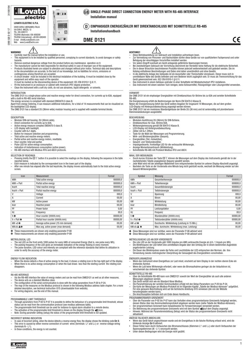
Doc: I305PLGB0510_DMED120T1 30/05/2010 s. 2 / 6
Wybór pomiarów
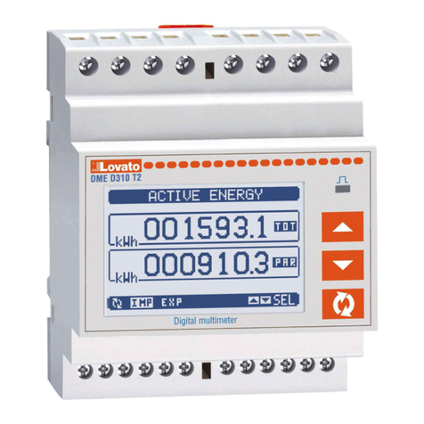
Wcisnąć na chwilęprzycisk co umożliwi wybór odczytów na
wyświetlaczu, w kolejności przedstawionej w tabeli poniżej.
Każdy pomiar jest określony odpowiedniąikonąw górnej części
wyświetlacza.
Po upływie jednej minuty, od momentu użycia przycisku po raz ostatni,
licznik automatycznie przechodzi do wyświetlania licznika energii czynnej.
Ikona Pomiar Format
kWh Całkowita energia czynna 000000,0
kWh + Par
Częściowa energia czynna 000000,0
kvarh Całkowita energia bierna
000000,0
varh + Par
Częściowa energia bierna 000000,0
Napięcie 000,0
A Prąd 00,00
Moc czynna 00,00
va
Moc bierna 00,00
PF Współczynnik mocy 0,00
Hz Częstotliwość 00,0
h
Licznik godzin (hhhhh.mm) 00000,00
h
+ Par
Częściowy licznik godzin
(hhhhh.mm) 00000,00
W +
Średnia moc czynna (zapotrz. z 15 min) 00,00
kW+
d +▲Max średnia moc czynna
(max zapotrz.) 00,00
Selection of readings
Pressing briefly the button it is possible to select the readings on
the display, following the sequence in the table reported below.
Each measure is indicated by the correspondent icon in the lower part of
the display.
After one minute has elapsed after the last keystroke, the display moves
automatically back to the total active energy screen.
Icon
Measure
Format
kWh
Total active energy 000000,0
kWh + Par
Partial active energy 000000,0
kvarh
Total reactive energy 000000,0
varh + Par
Partial reactive energy 000000,0
Voltage
000,0
A
Current
00,00
ctive power 00,00
va
Reactive power 00,00
PF
Power factor 0,00
Hz
Frequency
00,0
h
Hour counter (hhhhh.mm) 00000,00
h
+ Par
Partial hour counter (hhhhh.mm) 00000,00
W +
verage active power (15 min demand)
00,00
W+
+
Max avg. active power (max demand)
00,00
Te pomiary sąwyświetlane tylko przy włączonym parametrze P-08
Te pomiary sąwyświetlane tylko przy włączonym parametrze P-09
These measurements are shown only enabling parameter P-08
These measurements are shown only enabling parameter P-09
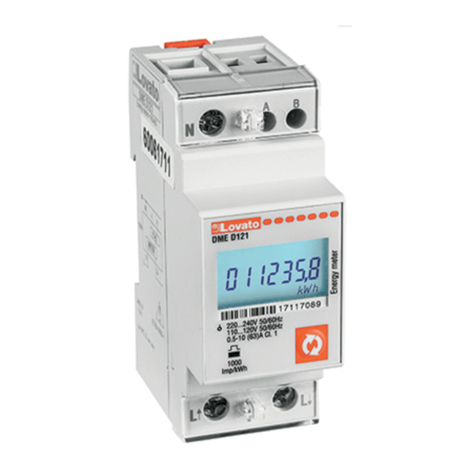
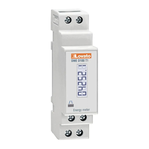
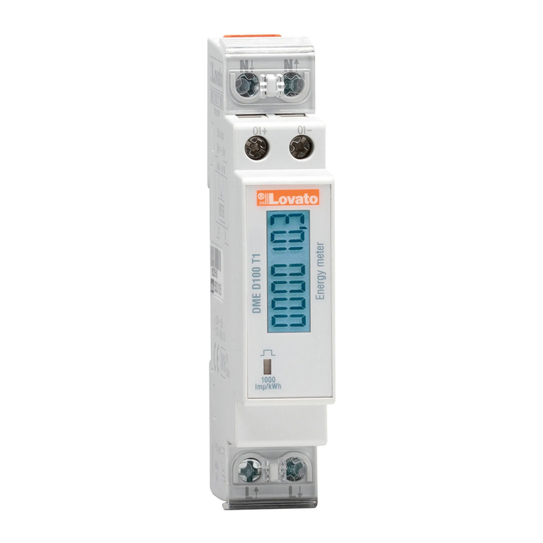
Dioda metrologiczna LED
Czerwona dioda LED na panelu przednim emituje 1000 impulsów dla
każdej zużytej kWh (jeden impuls dal każdej Wh).
Częstotliwość pulsowania diody LED wskazuje chwilowy przepływ energii
w każdym momencie.
Czas trwania impulsu, kolor diody LED i jej intensywność sązgodne
z odpowiednimi standardami, które definiująużytkowanie umożliwiające
weryfikacje dokładności licznika energii.
Metrological LED
The red LED on the front emits 1000 pulses for every kWh of consumed
Energy (that is, one pulse every Wh).
The pulsing frequency of the LED gives an immediate indication of the
energy flowing in every moment.
The pulse duration, LED colour and intensity are compliant with the
reference standards that define its utilization in order to verify the
accuracy of the energy meter.
Wskaźnik poboru energii
Kiedy urządzenie wykrywa przepływ energii do obciążenia na ekranie
wyświetlana jest obracająca sięikona po prawej stronie u góry ekranu.
Kiedy natomiast nie ma poboru energii czynnej lub kiedy prąd obciążenia
jest mniejszy niżprąd uruchomienia urządzenia obracająca sięikona znika.
Energy flow indication
When the device detects a flow of active energy to the load, it shows a
rotating icon in the top-right part of the display.
When there is no active energy consumption or when the load draws
less than the starting current the rotating icon disappears.
Programowalne izolowane wyjście statyczne
Wyjście statyczne umieszczone u góry licznika może byćwykorzystane
jako wyjście impulsowe lub jako wyjście alarmowe, po przekroczeniu
pewnych progów.
Podłączenie może byćwykonane w trybie PNP lub NPN. Zobacz schemat
podłączeńi dane techniczne w celu uzyskania większej ilości informacji
o podłączeniu i zakresach.
Aktywacja wyjścia statycznego oznaczona jest na ekranie ikoną.
Kiedy wyjście zaprogramowane jest generator impulsów możliwe jest
podłączenie licznika energii do:
Zewnętrznego rejestratora danych (jak np. DME CD)
Zdalnego licznika elektromechanicznego
Do sterownika PLC lub innego typu urządzenia.
Kiedy natomiast wyjście pracuje jako wyjście alarmowe to może byćużyte
do:
Odłączenia obciążenia nie-priorytetowego
Sygnalizacji alarmu
Uwaga: Podczas ustawiania parametrów (setup) status wyjścia statycznego
nie jest odświeżany.
Programmable insulated static output
The static output on the upper terminals can be used either as a pulse
output or as a measure threshold output.
The connection can be done in PNP or NPN mode. See schematic
diagrams and technical characteristics for details on the wiring and on
the rating.
The activation of the static output is shown on the display through the
icon.
When the output is programmed as a pulse generator, it allows
connecting the energy meter to:
An external data concentrator (like DME CD)
A remote electromechanical counter
A PLC or other device
When it works as an alarm threshold, it can be used for:
Disconnection of non-priority loads
Alarm signalling
Note: During parameter setting (setup) the status of the static output is
not updated.
Wskaźnik niewłaściwego podłączenia
W przypadku niewłaściwego okablowania, kiedy urządzenie wykryje
odwrotny przepływ energii, na ekranie pokaże sięmigający kod Err 3.
Ten błąd spowodowany jest przez odwrotne podłączenie przewodów
prądowych (zaciski Li L) lub przez odwrotne podłączenie przewodów
napięciowych (zaciski N - L).
W tych warunkach energia nie jest zliczana.
Incorrect wiring
indication
In case of incorrect wiring, when the device detects a reverse energy
flow, the display shows the blinking code Err 3.
This error is caused by either reverse connection of current wires
(terminals Land L) or reverse voltage wiring (terminals N - L).
In these conditions the energy is not counted.


