8
2. Installation
2.1 General criteria
A planned installation will make both fitting and operation of your Modular 100 watermaker easier.
Details below need to be taken into account with your installation:
An appropriate seawater intake with necessary fittings.
Positioning of Pump & Watermaker units .
Pipework and cable laying.
A good installation needs to be easy to use, easy to access for maintenance and filter changes. All
Watermaker components have been designed to achieve all of this. Draw a schematic electric and hy-
draulic connection diagram when the installation plan is complete and keep it with this manual for
reference.
2. Installation
2.2 Components mounting
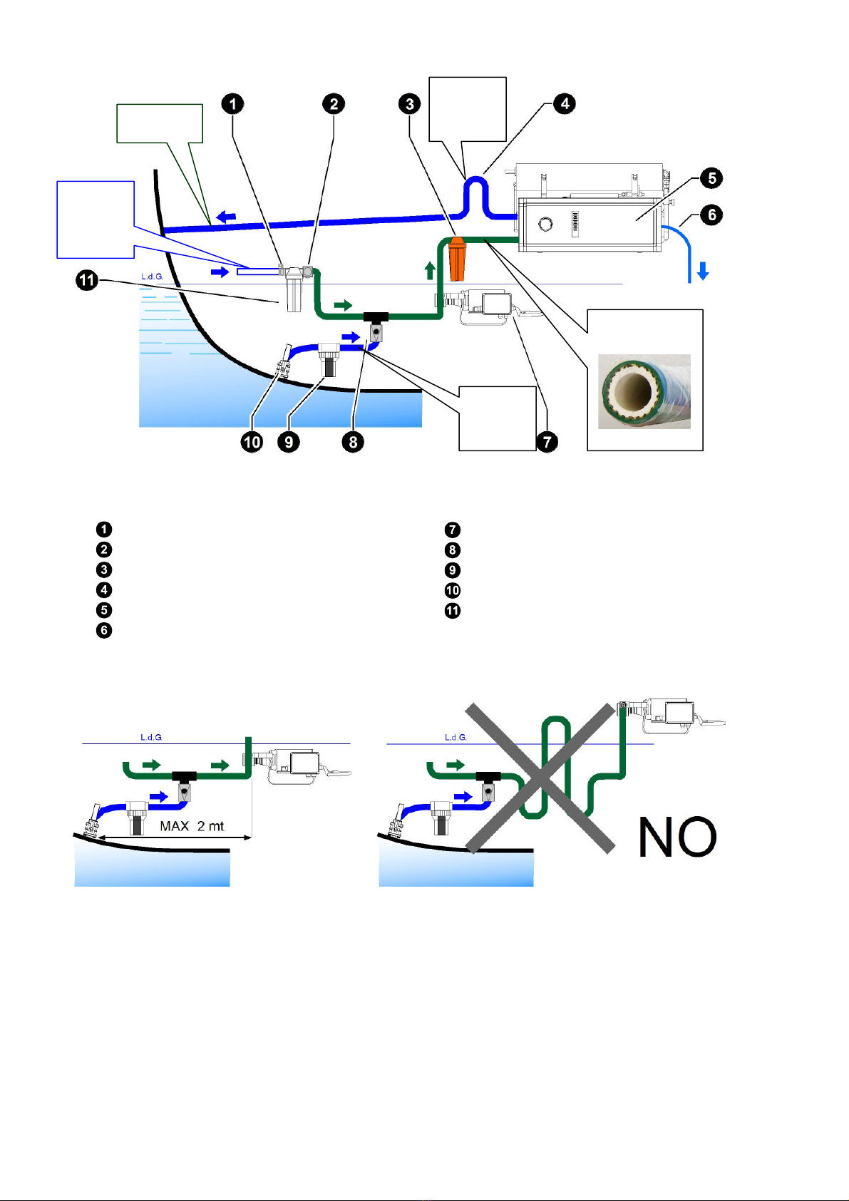
Pump group.
The pump is partially self-priming. Anyway it is strictly recommended to install the pump below the
watermaker, and as low as possible respect the sea level, and as close as possible respect the sea
water intake.
The pump cannot run dry. Therefore it is very important avoid to start the system if the intake valve is
closed or if inlet filters are clogged.
The pumps need to be installed in an adequately ventilated area to allow cooling and avoiding con-
densation.
Do not install the pumps unit close to inflammable liquids, as the pump surfaces can become warm.
Avoid locating the pump where a loss of water can cause damage or jeopardi e its safety.
The pump must be installed hori ontally on a suitable base strong enough to support its weight when
the filter housing is full of water.
It may be necessary to create a suitable wooden or fiberglass structure for the unit if an existing one
not available. The base of the pump is equipped with vibration-damping devices, but avoid installing
it on a surface susceptible to vibration.
The pumps unit can be a little noisy in operation. Possible areas for siting are: sink closets, under
berth lockers, wardrobe bases (creating a false floor above it.)
The max. allowed room temperature must be 40°C.
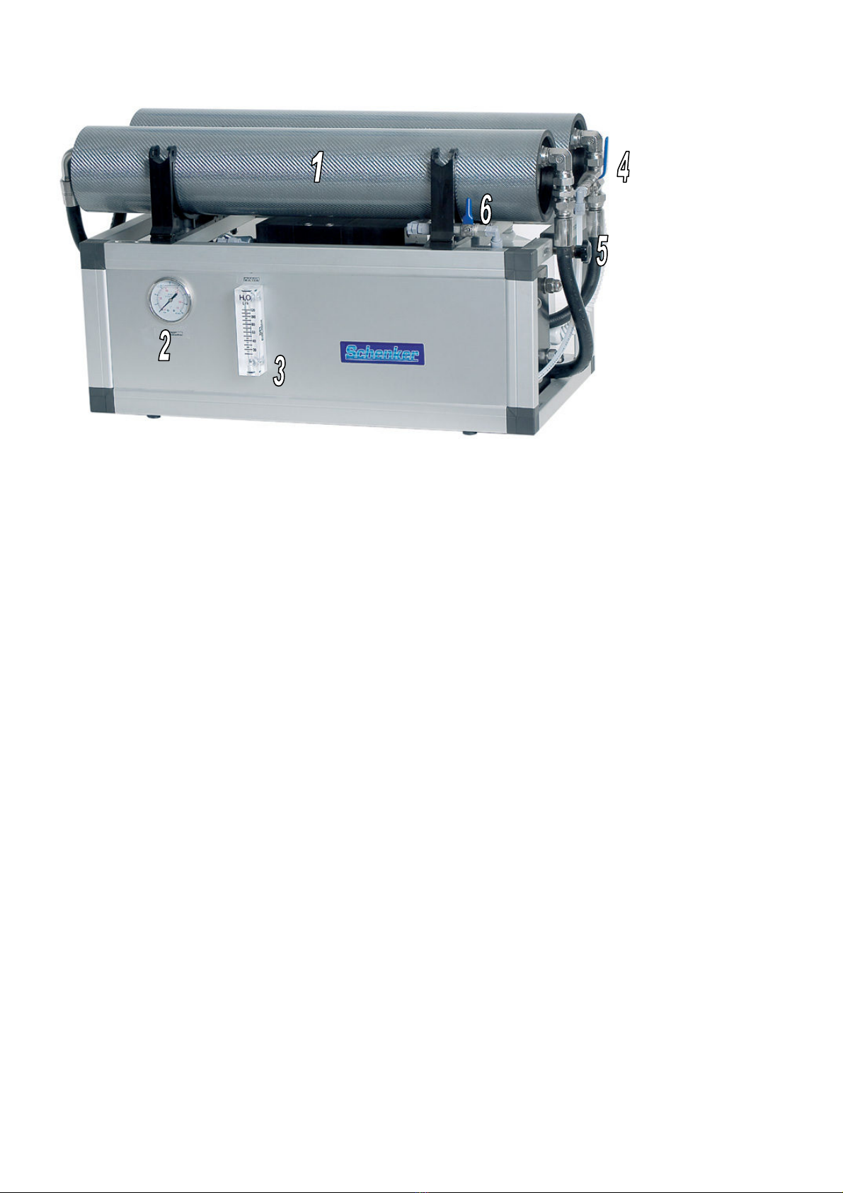
Watermaker group.
Concerning the watermaker unit installation there are not height limits in comparison to the seawater
level. Avoid to install the system wherever any possible leak may cause damages to the boat or jeop-
ardi e its safety, since possible leaks due to accidental causes (pipe bursting, hose clamp loosening,
equipment failure, etc.) may cause water losses.
The hydraulic intake and outlet connections are positioned, in the standard version, on the left of the
unit. Therefore, it is necessary to foresee a minimum distance of 20 cm. to allow the pipes laying. The
watermaker unit must be installed on a base sufficiently hori ontal, suitable to sustain the weight of
the group (approx. 55 Kg). It could be necessary to reali e a suitable wooden or fiberglass structure if
an hori ontal support is not available. The watermaker unit is equipped with vibration-damping de-
vices, but however it is preferable to not install the unit on a plan particularly subject to vibrations.
Possible locations of the watermaker group are: engine compartment, closets, and peak tank. It is ad-
visable to install the unit in such position to make the instrumentation easily visible, and make the
valves (located on the right of the unit) easily accessible.