Schenker xirios d301 User manual


Preface
V
Preface
Instructions for Care and Operation
The notebook computer is quite rugged, but it can be damaged. To prevent this, follow these suggestions:
1. Don’t drop it, or expose it to shock. If the computer falls, the case and the components could be damaged.
2. Keep it dry, and don’t overheat it. Keep the computer and power supply away from any kind of heating element. This
is an electrical appliance. If water or any other liquid gets into it, the computer could be badly damaged.
3. Follow the proper working procedures for the computer. Shut the computer down properly and don’t forget to save
your work. Remember to periodically save your data as data may be lost if the battery is depleted.
Do not expose the computer
to any shock or vibration.
Do not place it on an unstable
surface.
Do not place anything heavy
on the computer.
Do not expose it to excessive
heat or direct sunlight.
Do not leave it in a place
where foreign matter or mois-
ture may affect the system.
Don’t use or store the com-
puter in a humid environment.
Do not place the computer on
any surface which will block
the vents.
Do not turn off the power
until you properly shut down
all programs.
Do not turn off any peripheral
devices when the computer is
on.
Do not disassemble the com-
puter by yourself.
Perform routine maintenance
on your computer.

Preface
VI
Preface
4. Avoid interference. Keep the computer away from high capacity transformers, electric motors, and other strong mag-
netic fields. These can hinder proper performance and damage your data.
5. Take care when using peripheral devices.
Power Safety
The computer has specific power requirements:
• Only use a power adapter approved for use with this computer.
• Your AC adapter may be designed for international travel but it still requires a steady, uninterrupted power supply. If you are
unsure of your local power specifications, consult your service representative or local power company.
• The power adapter may have either a 2-prong or a 3-prong grounded plug. The third prong is an important safety feature; do
not defeat its purpose. If you do not have access to a compatible outlet, have a qualified electrician install one.
• When you want to unplug the power cord, be sure to disconnect it by the plug head, not by its wire.
• Make sure the socket and any extension cord(s) you use can support the total current load of all the connected devices.
• Before cleaning the computer, make sure it is disconnected from any external power supplies.
Use only approved brands of
peripherals.
Unplug the power cord before
attaching peripheral devices.
Do not plug in the power
cord if you are wet.
Do not use the power cord if
it is broken.
Do not place heavy objects
on the power cord.
Power Safety
Warning
Before you undertake
any upgrade proce-
dures, make sure that
you have turned off the
power, and discon-
nected all peripherals
and cables (including
telephone lines). It is
advisable to also re-
move your battery in
order to prevent acci-
dentally turning the
machine on.

Preface
VII
Preface
Battery Precautions
• Only use batteries designed for this computer. The wrong battery type may explode, leak or damage the computer.
• Do not continue to use a battery that has been dropped, or that appears damaged (e.g. bent or twisted) in any way. Even if the
computer continues to work with a damaged battery in place, it may cause circuit damage, which may possibly result in fire.
• Recharge the batteries using the notebook’s system. Incorrect recharging may make the battery explode.
• Do not try to repair a battery pack. Refer any battery pack repair or replacement to your service representative or qualified service
personnel.
• Keep children away from, and promptly dispose of a damaged battery. Always dispose of batteries carefully. Batteries may explode
or leak if exposed to fire, or improperly handled or discarded.
• Keep the battery away from metal appliances.
• Affix tape to the battery contacts before disposing of the battery.
• Do not touch the battery contacts with your hands or metal objects.
Battery Guidelines
The following can also apply to any backup batteries you may have.
• If you do not use the battery for an extended period, then remove the battery from the computer for storage.
• Before removing the battery for storage charge it to 60% - 70%.
• Check stored batteries at least every 3 months and charge them to 60% - 70%.
Battery Disposal
The product that you have purchased contains a rechargeable battery. The battery is recyclable. At the end of its useful life, under var-
ious state and local laws, it may be illegal to dispose of this battery into the municipal waste stream. Check with your local solid waste
officials for details in your area for recycling options or proper disposal.
Caution
Danger of explosion if battery is incorrectly replaced. Replace only with the same or equivalent type recommended by the manufacturer.
Discard used battery according to the manufacturer’s instructions.
Battery Level
Click the battery icon in the taskbar to see the current battery level and charge status. A battery that drops below a level of 10%
will not allow the computer to boot up. Make sure that any battery that drops below 10% is recharged within one week.

Preface
VIII
Preface
Related Documents
You may also need to consult the following manual for additional information:
User’s Manual on CD/DVD
This describes the notebook PC’s features and the procedures for operating the computer and its ROM-based setup pro-
gram. It also describes the installation and operation of the utility programs provided with the notebook PC.
System Startup
1. Remove all packing materials.
2. Place the computer on a stable surface.
3. Insert the battery and make sure it is locked in position.
4. Securely attach any peripherals you want to use with the computer
(e.g. keyboard and mouse) to their ports.
5. Attach the AC/DC adapter to the DC-In jack at the left of the
computer, then plug the AC power cord into an outlet, and connect
the AC power cord to the AC/DC adapter.
6. Use one hand to raise the
lid/LCD to a comfortable viewing angle
(do not exceed 120 degrees)
;
use the other hand (as illustrated in
Figure 1) to support the base of the computer (Note: Never lift the
computer by the lid/LCD).
7. Press the power button to turn the computer “on”.
Shut Down
Note that you should al-
ways shut your com-
puter down by
choosing Shut Down
from the Start Menu.
This will help prevent
hard disk or system
problems.
120 ゚
Figure 1
Opening the Lid/LCD/
Computer with AC/DC
Adapter Plugged-In

Preface
IX
Preface
What to do if you Spill Liquid on the Computer
The keyboard incorporates a drainage system that minimizes the chances of liquid spillages on the keyboard penetrating the inside
components of the computer. Liquid spilled on the computer is drained towards the right side of the computer. There is no guarantee
that all water can be prevented from entering the computer, and damage resulting from spillages is not covered in the warranty. How-
ever if you follow the steps outlined here you should be able to prevent water from entering the sensitive parts of the computer and
causing damage.
1. If you spill liquid on the computer immediately save any data required and then shut the computer down and disconnect the AC/DC adapter.
2. Carefully lift the computer up and tilt it to a 90 degree angle towards the right side (i.e. that right side of the computer should be at the bottom to
allow the water to drain away from the right side and not the left).
3. Move the computer to a dry place and wipe any liquid off the keyboard and bottom of the computer using a clean, soft, dry cloth.
4. Remove the battery.
5. Leave the computer resting on its right side (while placed on a clean, soft, dry cloth) to dry out for about three hours.
6. Contact your service center to have the computer examined for any problems, but do not attempt to turn the computer back on again until after it
has been examined.
Warranty Warning
Note that the keyboard drainage sys-
tem is designed to help prevent and
minimize damage from liquid spillag-
es on the computer keyboard. How-
ever damage resulting from spillages
is not covered in the warranty.
Figure 2 - Drain any Liquid to the Right Side and
Rest the Computer on the Right Side to Dry

Introduction
1 - 2 Specifications
1.Introduction
Specifications
Latest Specification Information
The specifications listed here are correct at the
time of sending them to the press. Certain items
(particularly processor types/speeds) may be
changed, delayed or updated due to the manu-
facturer's release schedule. Check with your
service center for more details.
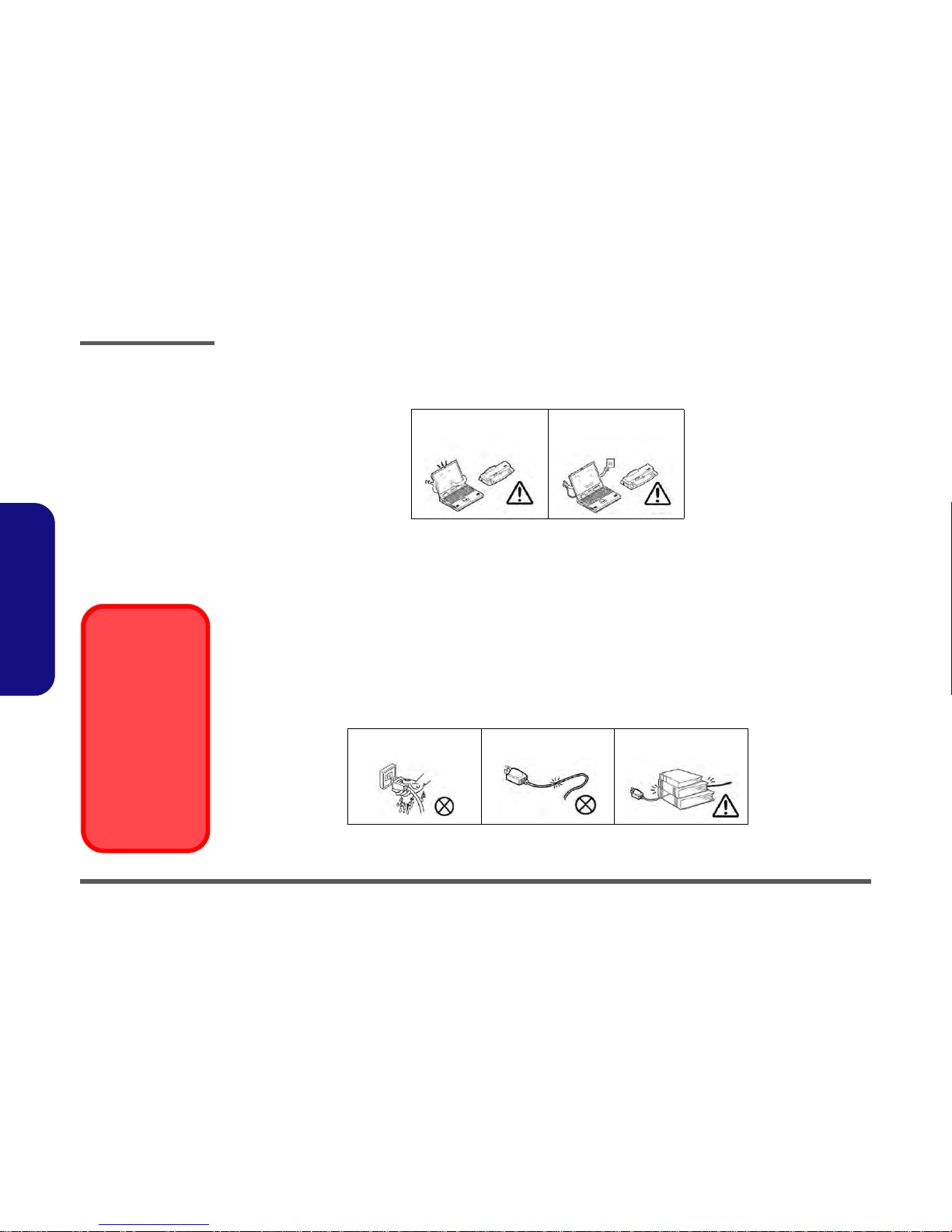
CPU
The CPU is not a user serviceable part. Ac-
cessing the CPU in any way may violate your
warranty.
Processor Options
W130HU:
Intel® Core™ i7 Processor
i7-2640M (2.80GHz), i7-2620M (2.70GHz)
4MB L3 Cache, 32nm, DDR3-1333MHz, TDP 35W
Intel® Core™ i5 Processor
i5-2540M (2.60GHz), i5-2520M (2.50GHz),
i5-2410M (2.30GHz)
3MB L3 Cache, 32nm, DDR3-1333MHz, TDP 35W
Intel® Core™ i3 Processor
i3-2330M (2.20GHz), i3-2310M (2.10GHz),
3MB L3 Cache, 32nm, DDR3-1333MHz, TDP 35W
Intel® Pentium™ Processor
B950 (2.10GHz), B940 (2.00GHz)
2MB L3 Cache, 32nm, DDR3-1333MHz, TDP 35W
W130HV:
Intel® Core™ i7 Processor
i7-2640M (2.80GHz), i7-2620M (2.70GHz)
4MB L3 Cache, 32nm, DDR3-1333MHz, TDP 35W
Intel® Core™ i5 Processor
i5-2540M (2.60GHz), i5-2520M (2.50GHz)
3MB L3 Cache, 32nm, DDR3-1333MHz, TDP 35W
LCD
13.3" (33.78cm) HD LCD
BIOS
W130HU:
AMI BIOS (One 32Mb SPI Flash ROM)
W130HV:
AMI BIOS (One 64Mb SPI Flash ROM)
Core Logic
W130HU:
Intel® HM65 Chipset
W130HV:
Intel® QM67 Chipset
Memory
Two 204 Pin SO-DIMM Sockets Supporting DDR3 1333MHz
Memory
Memory Expandable up to 8GB
(The real memory operating frequency depends on the FSB
of the processor.)
Video Adapter
Intel Integrated GPU (Intel® HD Graphics 3000):
Shared Memory Architecture (DVMT) up to 1.7GB
Microsoft DirectX®10 Compatible
Storage
One Changeable 2.5" 9.5 mm (h) SATA (Serial) HDD
Anti-Shock System
Audio
High Definition Audio Compliant Interface
2 * Built-In Speakers
Built-In Microphone
Security
BIOS Password
Security (Kensington® Type) Lock Slot
Fingerprint Reader
TPM v1.2
Intel vPro ( W130HV only)

Introduction
Specifications 1 - 3
1.Introduction
Keyboard
Isolated A4 Size Keyboard with Anti-Spray Support
Interface
One Powered USB 2.0 Port (see page 8)
Two USB 3.0 Ports
One eSATA/USB 2.0 Combo Port
One HDMI-Out Port
One Headphone-Out Jack
One Microphone-In Jack
One RJ-45 LAN Jack
One External Monitor Port
One ExpressCard/34(54) Slot
One DC-in Jack
(Factory Option) One Docking Port
Communication
Built-In Gigabit Ethernet LAN
(Factory Option) 1.3M Pixel USB PC Camera Module
(Factory Option) 3.75G/HSPA Mini-Card Module
WLAN/ Bluetooth Half Mini-Card Modules:
W130HU:
(Factory Option) Intel® Centrino® Advanced-N 6230 Wire-
less LAN (802.11a/g/n) + Bluetooth 3.0
(Factory Option) Intel® Centrino® Wireless-N 1030 Wire-
less LAN (802.11b/g/n) + Bluetooth 3.0
(Factory Option) Intel® Centrino® Wireless-N 1000 Wire-
less LAN (802.11b/g/n)
(Factory Option) Third-Party Wireless LAN (802.11b/g/n) +
Bluetooth 3.0
(Factory Option) Third-Party Wireless LAN (802.11b/g/n)
W130HV:
(Factory Option) Intel® Centrino® Advanced-N 6230 Wire-
less LAN (802.11a/g/n) + Bluetooth 3.0
Pointing Device
Built-in Touchpad (scrolling key functionality integrated)
Card Reader
Embedded Multi-in-1 Card Reader
MMC (MultiMedia Card) / RS MMC
SD (Secure Digital) / Mini SD / SDHC/ SDXC
MS (Memory Stick) / MS Pro / MS Duo
Mini Card Slots
Slot 1 for WLAN Module or WLAN and Bluetooth Combo
Module
(Factory Option) Slot 2 for 3.75G/HSPA Module
Environmental Spec
Temperature
Operating: 5°C - 35°C
Non-Operating: -20°C - 60°C
Relative Humidity
Operating: 20% - 80%
Non-Operating: 10% - 90%
Power
Full Range AC/DC Adapter
AC Input: 100 - 240V, 50 - 60Hz
DC Output: 19V, 3.42A or 18.5V, 3.5A (65W)
6 Cell Smart Lithium-Ion Battery Pack, 62.16WH
Dimensions & Weight
330mm (w) * 225mm (d) * 24.5 - 32mm (h)
1.78kg with ODD & 62.16WH Battery

Introduction
1 - 4 External Locator - Top View with LCD Panel Open
1.Introduction
External Locator - Top View with LCD Panel Open
Figure 1
Top View
1. PC Camera
(Optional)
2. LCD
3. Power Button
4. Keyboard
5. Built-In
Microphone
6. Touchpad &
Buttons
7. Fingerprint Reader
8. LED Status
Indicators
2
4
1
3
56
8
7

Introduction
External Locator - Front & Right Side Views 1 - 5
1.Introduction
External Locator - Front & Right Side Views
Figure 2
Front View
1. LED Power
Indicator
2. WLAN Switch
Figure 3
Right Side View
1. Microphone-In
Jack
2. Headphone-Out
Jack
3. USB 2.0 Port
4. Vent
5. Security Lock
Slot
FRONT VIEW
12
RIGHT SIDE VIEW
1 2 3
5
4

Introduction
1 - 6 External Locator - Left Side & Rear View
1.Introduction
External Locator - Left Side & Rear View
/
Figure 4
Left Side View
1. DC-In Jack
2. External Monitor
Port
3. RJ-45 LAN Jack
4. e-SATA Port/USB
2.0 Combo Port
5. HDMI-Out Port
6. 2 * USB 3.0 Ports
7. ExpressCard/
54(34) Slot
8. Multi-in-1 Card
Reader
LEFT SIDE VIEW
12 3 4 5 668
7
Figure 5
Rear View
1. Battery
REAR VIEW
1

Introduction
External Locator - Bottom View 1 - 7
1.Introduction
External Locator - Bottom View
Figure 6
Bottom View
1. Battery
2. Docking Port
3. Vent
4. Component Bay
Cover
5. Drainage Outlet
6. Speakers
Overheating
To prevent your com-
puter from overhea-
ting, make sure no-
thing blocks any vent
while the computer is
in use.
2
3
1
5
3 3
6
63
4

Disassembly
2 - 2 Overview
2.Disassembly
NOTE: All disassembly procedures assume that the system is turned OFF, and disconnected from any power supply (the
battery is removed too).
Maintenance Tools
The following tools are recommended when working on the notebook PC:
• M3 Philips-head screwdriver
• M2.5 Philips-head screwdriver (magnetized)
• M2 Philips-head screwdriver
• Small flat-head screwdriver
• Pair of needle-nose pliers
• Anti-static wrist-strap
Connections
Connections within the computer are one of four types:
Locking collar sockets for ribbon connectors To release these connectors, use a small flat-head screwdriver to
gently pry the locking collar away from its base. When replac-
ing the connection, make sure the connector is oriented in the
same way. The pin1 side is usually not indicated.
Pressure sockets for multi-wire connectors To release this connector type, grasp it at its head and gently
rock it from side to side as you pull it out. Do not pull on the
wires themselves. When replacing the connection, do not try to
force it. The socket only fits one way.
Pressure sockets for ribbon connectors To release these connectors, use a small pair of needle-nose pli-
ers to gently lift the connector away from its socket. When re-
placing the connection, make sure the connector is oriented in
the same way. The pin1 side is usually not indicated.
Board-to-board or multi-pin sockets To separate the boards, gently rock them from side to side as
you pull them apart. If the connection is very tight, use a small
flat-head screwdriver - use just enough force to start.

Disassembly
Overview 2 - 3
2.Disassembly
Maintenance Precautions
The following precautions are a reminder. To avoid personal injury or damage to the computer while performing a re-
moval and/or replacement job, take the following precautions:
1. Don't drop it. Perform your repairs and/or upgrades on a stable surface. If the computer falls, the case and other
components could be damaged.
2. Don't overheat it. Note the proximity of any heating elements. Keep the computer out of direct sunlight.
3. Avoid interference. Note the proximity of any high capacity transformers, electric motors, and other strong mag-
netic fields. These can hinder proper performance and damage components and/or data. You should also monitor
the position of magnetized tools (i.e. screwdrivers).
4. Keep it dry. This is an electrical appliance. If water or any other liquid gets into it, the computer could be badly
damaged.
5. Be careful with power. Avoid accidental shocks, discharges or explosions.
•Before removing or servicing any part from the computer, turn the computer off and detach any power supplies.
•When you want to unplug the power cord or any cable/wire, be sure to disconnect it by the plug head. Do not pull on the wire.
6. Peripherals – Turn off and detach any peripherals.
7. Beware of static discharge. ICs, such as the CPU and main support chips, are vulnerable to static electricity.
Before handling any part in the computer, discharge any static electricity inside the computer. When handling a
printed circuit board, do not use gloves or other materials which allow static electricity buildup. We suggest that
you use an anti-static wrist strap instead.
8. Beware of corrosion. As you perform your job, avoid touching any connector leads. Even the cleanest hands pro-
duce oils which can attract corrosive elements.
9. Keep your work environment clean. Tobacco smoke, dust or other air-born particulate matter is often attracted
to charged surfaces, reducing performance.
10. Keep track of the components. When removing or replacing any part, be careful not to leave small parts, such as
screws, loose inside the computer.
Cleaning
Do not apply cleaner directly to the computer, use a soft clean cloth.
Do not use volatile (petroleum distillates) or abrasive cleaners on any part of the computer.
Power Safety
Warning
Before you undertake
any upgrade proce-
dures, make sure that
you have turned off the
power, and discon-
nected all peripherals
and cables (including
telephone lines). It is
advisable to also re-
move your battery in
order to prevent acci-
dentally turning the
machine on.

Disassembly
Removing the Battery 2 - 5
2.Disassembly
Removing the Battery
1. Turn the computer off, and turn it over.
2. Slide the latch in the direction of the arrow (Figure 1a).
3. Slide the latch in the direction of the arrow, and hold it in place (Figure 1a).
4. Slide the battery in the direction of the arrow (Figure 1b).
3. Battery
1
2
6
3
4
Figure 1
Battery Removal
a. Slide the latch and hold it
in place.
b. Slide the battery in the di-
rection of the arrow.
a. b.
3
4
12

Disassembly
2 - 6 Removing and Installing the Hard Disk Drive
2.Disassembly
Removing and Installing the Hard Disk Drive
Hdd Removal Procedure
The hard disk drive can be taken out to accommodate other 2.5" serial (SATA) hard disk drives with a height of 9.5mm
(h). Follow your operating system’s installation instructions, and install all necessary drivers and utilities (as outlined in
Chapter 4 of the User’s Manual) when setting up a new hard disk.
Hard Disk Upgrade Process
1. Turn off the computer, and remove the battery (page 2 - 5).
2. Slide the latch in the direction of the arrow and slide the latch in the direction of the arrow, and hold it in
place and carefully slide the cover in the direction of the arrow to align with the markers on the case .
3. Lift the component bay cover off the computer.
4. When reinserting the cover align the markers on the case and cover first, and then slide the cover until it clicks
into place.
Figure 2
HDD Assembly
Removal
a. Slide the latches and
atch hold it in place.
b. Remove the component
bay cover.
2
HDD System Warning
New HDD’s are blank.
Before you begin make
sure:
You have backed up
any data you want to
keep from your old
HDD.
You have all the CD-
ROMs and FDDs re-
quired to install your op-
erating system and
programs.
If you have access to
the internet, download
the latest application
and hardware driver up-
dates for the operating
system you plan to in-
stall. Copy these to a re-
movable medium.
1
2
3
4
6
5
4
2 1
3
4 4
b.a.
5
5. Component Bay Cover

Disassembly
Removing and Installing the Hard Disk Drive 2 - 7
2.Disassembly
5. Raise the plastic tab .
6. Slide the hard disk assembly in the direction of arrow until you can see the (gold colored) HDD connector .
7. When the connector can be viewed, lift the assembly up in the direction of arrow remove the HDD assembly
from the bay.
8. Remove the screws & and the mylar cover from the hard disk (Figure 3e)..
6
7
8
6
9
10
11
12
13
4
6
7
8
c.
d.
e.
9
9
f.
12
13
11
10
Figure 3
HDD Assembly
Removal (cont’d.)
c. Raise the plastic tab.
d. Grip the tab and slide the
HDD assembly in the di-
rection of the arrow.
e. Lift the HDD assembly
out of the bay.
f. Remove the screws and
mylar cover.
9. HDD Assembly
12. Mylar Cover
13. HDD
•2Screws

Disassembly
2 - 8 Removing and Installing the Hard Disk Drive
2.Disassembly
Reinserting the HDD
1. To reinsert the HDD assembly hold it carefully at the four corners between your thumb and forefinger and Insert
the HDD directly down into the bay vertically (Figure 1a).
2. Press and slide the HDD assembly at the area illustrated (do not press on the center area - see sidebar) the
direction of arrows to make sure the HDD fits securely into the connector.
3. Press down on the rubber case to ensure the assembly is properly seated before replacing the cover and
screws.
4. Replace the component bay cover (page 2 - 6).).
Figure 4
HDD Installation
a. Insert the HDD di-
rectly down into the
bay vertically.
b. Press and slide the
HDD assembly at the
area illustrated
c. Press down on the
rubber case
Hard Disk Handling
Do not press down on the
center off the hard disk as
this area houses the hard
disk drive motor.
2
6
1
2
3
2
3
3
a. c.
b.
2
1
1. HDD Assembly

Disassembly
Removing the System Memory (RAM) 2 - 9
2.Disassembly
Removing the System Memory (RAM)
The computer has two memory sockets for 204 pin Small Outline Dual In-line Memory Modules (SO-DIMM) supporting
DDRIII (DDR3) Up to 1333 MHz. The main memory can be expanded up to 8GB. The SO-DIMM modules supported
are 1024MB and 2048MB DDRIII Modules. The total memory size is automatically detected by the POST routine once
you turn on your computer.
Memory Upgrade Process
1. Turn off the computer, turn it over and remove the battery (page 2 - 5) and remove the component bay cover
(page 2 - 6).
2. The RAM modules will be visible at point on the mainboard.
3. Gently pull the two release latches ( & ) on the sides of the memory socket in the direction indicated by the
arrows (Figure 5b). The RAM module will pop-up (Figure 5c), and you can then remove it.
4. Pull the latches to release the second module if necessary.
5. Insert a new module holding it at about a 30° angle and fit the connectors firmly into the memory slot.
6. The module will only fit one way as defined by its pin alignment. Make sure the module is seated as far into the slot
as it will go. DO NOT FORCE IT; it should fit without much pressure.
7. Press the module in and down towards the mainboard until the slot levers click into place to secure the module.
8. Replace the component bay cover (see page 2 - 6).
9. Restart the computer to allow the BIOS to register the new memory configuration as it starts up.
Figure 5
RAM Module
Removal
a. The RAM modules will
be visible at point
on the mainboard.
b. Pull the release lat-
ches.
c. Remove the module.
Contact Warning
Be careful not to touch
the metal pins on the
module’s connecting
edge. Even the cleanest
hands have oils which
can attract particles, and
degrade the module’s
performance.
1
• 4 RAM Module
1
2
3
4
b. c.
2
4
a.
1
3

Disassembly
Removing the 3.75G Module 2 - 13
2.Disassembly
Removing the 3.75G Module
1. Turn off the computer, turn it over, and remove the battery (page 2 - 5) and the component bay cover (page 2 - 9).
2. The 3.75G module will be visible at point on the mainboard (Figure 9a).
3. Carefully disconnect the cable , and then remove the screw (Figure 9b).
4. The 3.75G module will pop-up, and you can remove it from the computer (Figure 9c).
Figure 9
3G Module Removal
a. Locate the 3.75G mod-
ule.
b. Disconnect the cable
and remove the screw.
c. The module will pop-up
and remove the 3.75G
module.
Note: Make sure you
reconnect the antenna
cable to socket.
1
2
3
4
b.
c.
a.
3
2
4
4
1
4. 3.75G Module
•1Screw
Table of contents
Other Schenker Laptop manuals

Schenker
Schenker XMG P724 User manual

Schenker
Schenker s413 User manual

Schenker
Schenker XMG P511 User manual

Schenker
Schenker XMG P505 User manual

Schenker
Schenker W703 User manual

Schenker
Schenker M504 User manual

Schenker
Schenker XMG U726 User manual

Schenker
Schenker PC70DS User manual

Schenker
Schenker F516 User manual

Schenker
Schenker W504 User manual

Schenker
Schenker XMG A722 User manual

Schenker
Schenker s413 User manual

Schenker
Schenker XIRIOS D501 User manual

Schenker
Schenker M505 User manual

Schenker
Schenker S306 User manual

Schenker
Schenker GM5MG0O User manual

Schenker
Schenker a522 User manual

Schenker
Schenker XMG A502 User manual

Schenker
Schenker WORK 15 User manual

Schenker
Schenker M704 User manual