Schertler arthur User manual

ACOUSTIC FIDELITY
arthur
ART48 - AUXMAST
USER MANUAL
Assembling instruction on ART48-L/Rmast manual

WARNINGS
PRECAUTIONS
WARNINGS Read carefully this manual and follow these
precautions before operating the device
Keep this manual for possible future needs
Pay attention not to pour liquids onto the device and do not operate in conditions of excessive humidity
Do not install the device close to sources of excessive heat, do not expose it to direct solar radiation and do not
position it without protection in a dusty environment
Be sure that the main voltage does not exceed the value indicated on the back panel
Do not use the device if the main cable or the plug aren’t in a perfect condition (if necessary, replace it)
If the main cable has to be replaced, the operation must be carried out by qualied personnel. Replace the cable
exclusively with one that is an exact substitute
In order to avoid interference, do not install the device close to power transformers, TV sets, RF transmitters, electric
motors or any source of electric energy
Do not point microphones against speakers: this could generate annoying whistles (Larsen effect) that cause damage
In order to avoid unpleasant and costly inconveniences, use only original connecting cables
To completely disconnect this apparatus from the AC mains, disconnect the power supply cord plug from the AC socket
When cleaning, do not use solvents (e.g. acetone or alcohol). These could damage the external nishing and the
serigraphy
Do not attempt to service this product. In case of malfunction of any part of the system call the nearest technical
assistance centre or a specialized technical centre
For good ventilation, the heat sink should never be covered or obstructed by blankets, sofas or similar furniture. Be
sure also to leave sufcient clearance between the heat sink and any other surface
No source of ames, e.g. candles, should be placed on or near the device
The device should not be exposed to water, even in small amounts. No object containing liquids should be placed on
or near the device
The device should only be connected to a mains socket outlet equipped with protection ground system
When the device is installed, be sure the mains socket and the plug of the mains cable are easily accessible

ART48 - AUXMAST
The Arthur AUX master unit is a very ne, high-end, CLASS-A output amp. It has been
designed to function as an additional output unit for the L/R master unit, completing your
mixer and providing all routings as well as additional output functions. In this respect, the
mixer’s entire master section consists of the L/R master unit, the AUX master unit and a
master EQ unit, in case a correction of the room acoustic is required.
++
++
++
++
++
-
+
++
++
++
++
++
++
++
++
++
++
++
++
+6dB
+6dB
+6dB
+6dB
+6dB
room level
level
level
L
R
talkback to AUX 2
room out R
stereo jack
balanced
room out L
mono
main
PFl
phone vol
stereo jack
phone stereo out
phone amp
all pots and switches in blu color
all plugs and bus in red color
stereo jack
balanced
talkback OUT
talkback level
ON
stereo jack
balanced
stereo jack
balanced
R main
L main
PFl
level
PFL OUT
AUX 2 OUT
A UX 3
stereo jack
balanced
summing amp
SCHERTLER
summing amp
AUX 3 OUT
BUS
summing amp
+48V
A UX 2
blockdiagram
modular mixer 2.2015
AUX master

ART48 - AUXMAST
Let’s take a look at the additional functions the AUX master unit adds
to your Arthur mixer.
It makes sense to install the AUX master unit to the right of the L/R
master unit. This way the AUX faders will go from left to right in
numeric order (AUX 1 on the L / R master, AUX 2 and AUX 3 on the
AUX master).
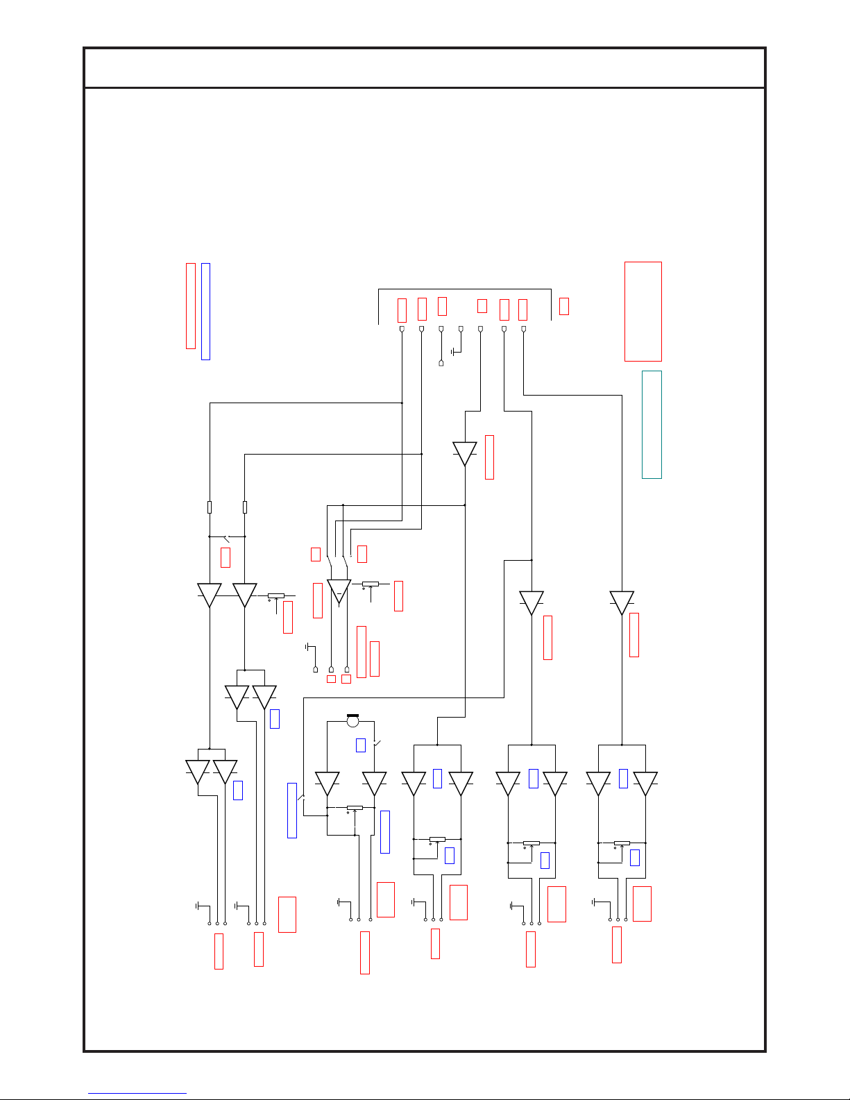
The AUX master unit includes six output amps.
Please note that all six phone plugs are designed to send balanced
signals, realized via space-saving stereo phone plugs. The tip
connects as usual to the hot signal (+), the ring to the cold signal (-)
and the sleeve to the ground.
An additional advantage of phone plugs is that they also allow you to
connect an unbalanced music signal, via a mono jack, to any of the
outputs.
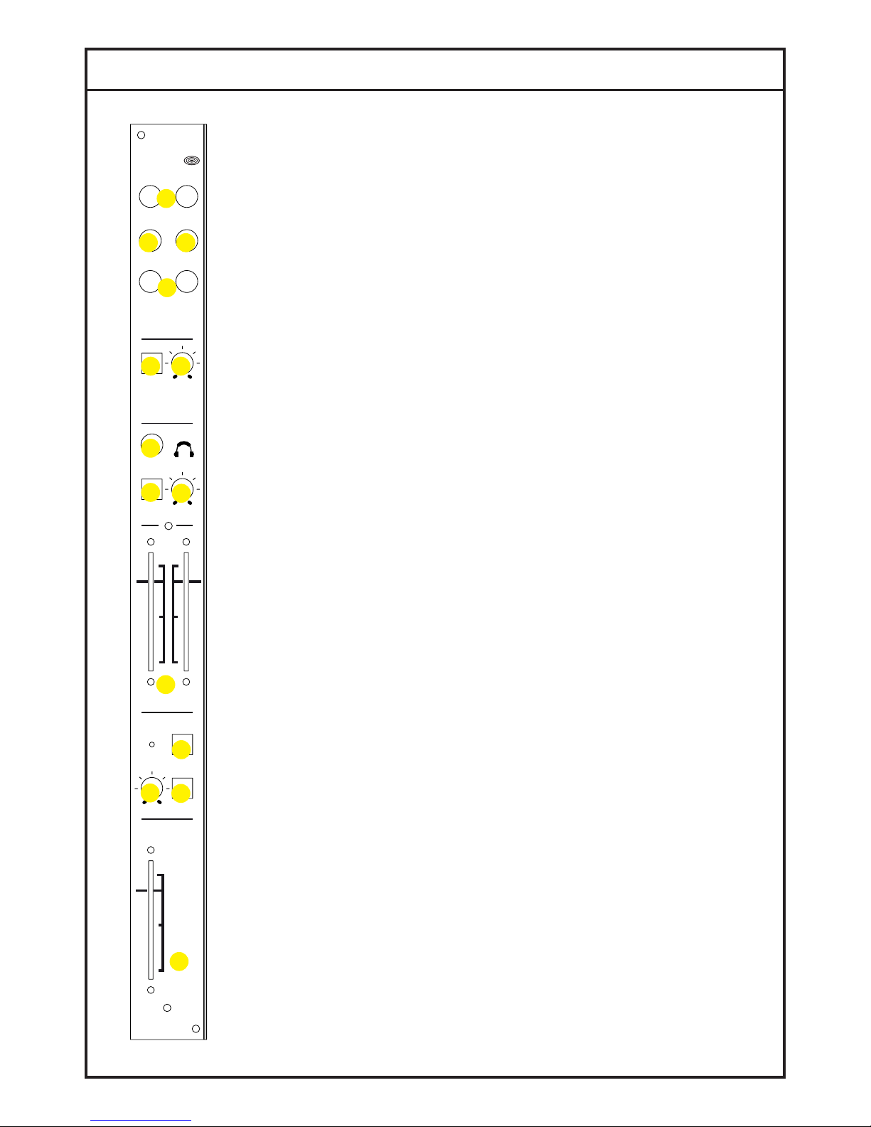
The unit’s PFL (pre fade listen) function is similar to that of other mixers.
However, as well as being a traditional PFL, this one also serves as a
fourth AUX send, but without the possibility to independently set the
level on all channels.
All signals from any input units that have their PFL buttons depressed
(red light), will be controlled via the PFL fader (2.) at the bottom of
the AUX master unit and sent to the output via the PFL OUT (3.) at
the top of the unit. (The PFL function of the headphones will not be
affected by this fader.)
This particular function can be useful when an additional monitor is
needed, for example for a singer, where only one signal might be
required (in this case the signal from the “voice channel”).
The AUX 2 and AUX 3 faders (4.) (located in the middle of the unit)
control the amount of signal on the AUX 2 OUT and AUX 3 OUT (5.)
respectively.
The AUX master unit also includes a talkback section with an integrated
condenser microphone (you will nd the mic port to the left of the TO
AUX 2 button (6.)). This is designed to ease the sound engineer’s
communication with the stage or recording room. To activate the
talkback section, simply depress the TB ON button (7.) (yellow light).
The preamplied signal from the microphone can be connected from
the TB OUT to any (active) loudspeaker system (in the recording
room), or sent directly to the AUX 2 OUT output by depressing the TO
AUX 2 button, thereby adding it to the AUX 2 signal heard in the stage
monitors for example. (Therefore, use AUX 2 for stage monitors.)
Set the correct level of talkback (8.) using the dedicated VOLUME
format48
AUX master
AUX 2 AUX 3
PFLT B
CONTROL
ROOM
LCTRL
ROOM
MON
OUT
PHONES
VOLUME
PFL
-
8
dB
0
+6
-25
TALK BACK
TO
AUX2
ONVOLUME
PFL
-
8
dB
0
+6
-25
AUX3
AUX2
BALANCED
OUTPUTS
Arthur
R
MIC
4.
1.
2.
3.
6.
7.
9.
14.
13.
10.
11.12.
5.
8.
OVOLUME

ART48 - AUXMAST
knob (9.). Don’t forget to deactivate the TB ON button when you have nished speaking
over the talkback!!
Using the headphones section is very simple: Connect your headphones to the HP OUT
(14.) and adjust the VOLUME knob (13.) to a comfortable sound level. You will hear the
music signal from the L/R master independently from the signal level that is determined
by the position of the master faders.
When you depress the PFL to HP (1.) button (red light), the PFL signal will appear on
the headphones, provided that the PFL button is depressed on at least one of the input
channels. This function can be helpful when listening to one input channel exclusively,
or when listening to it before fading it to the main outputs, by having deactivated the
channel (ON / OFF button) or having pushed down the channel’s fader.
The control room section is an additional stereo L/R output (10.) that could drive devices
such as room monitors in a recording studio. Other devices could also receive a stereo
signal from this output, e.g. a subsidiary PA, side lls, a second recording device etc.
Plug the active studio monitors (or the amp to drive passive monitors) into the LEFT and
RIGHT outputs. Set the audio level by turning the VOLUME knob (11.).
The MONO button (12.) will help you listen to a stereo program that has been reproduced
in mono, in order to evaluate its “mono compatibility”.

TECHNICAL SPECS
Control Room L/R balanced ¼” jack
outputs
Output impedance
Maximum output level
Frequency response (-3dB)
Distortion (THD+N; @1kHz)
-30dBu input level
0dBu output level
AUX 2, AUX 3 balanced ¼” jack outputs
Output impedance
Maximum output level
Maximum Gain
Frequency response (-3dB)
PFL balanced ¼” jack output
Output impedance
Maximum output level
Maximum Gain:
Frequency response (-3dB)
Distortion (THD+N; @1kHz)
-30dBu input level
0dBu output level
Phones ¼” jack output
Output impedance
Maximum output level
Frequency response (-3dB)
Distortion (THD+N; @1kHz)
Power consumption
Size & Weight
200 ohm
+25dBu (@1kHz ; THD <0.5%)
20Hz – 60 kHz
0.12%
180 ohm
+26dBu (@1kHz ; THD <0.5%)
+13 dB
16Hz – 125 kHz
190 ohm
+25dBu (@1kHz ; THD <0.5%)
+6 dB
16Hz – 100 kHz
0.05%
20 kohm
+10 dBu (@1kHz unity Gain; THD <0.5%)
16Hz - 100kHz
0.12% (@ unity Gain)
67 mA
36x58x475mm ; 0,5 kg

IMPORTANT SAFETY INSTRUCTIONS
THE LIGHTNING FLASH WITH ARROWHEAD SYMBOL, WITHIN AN EQUILATERAL TRIANGLE, IS INTENDED TO ALERT THE USER TO THE PRESENCE OF
UNINSULATED “DANGEROUS VOLTAGE” WITHIN THE PRODUCT ENCLOSURE THAT MAY BE OF A SUFFICIENT MAGNITUDE TO CONSITUTE A RISK OF
ELECTRIC SHOCK TO PERSONS.
THE EXCLAMATION POINT WITHIN AN EQUILATERAL TRIANGLE, IS INTENDED TO ALERT THE USER TO THE PRESENCE OF IMPORTANT OPERATING AND
MAINTENANCE INSTRUCTIONS IN THE LITERATURE ACCOMPANYING THE PRODUCT.
WARNING TO REDUCE THE RISK OF FIRE OR ELECTRICAL SHOCK
DO NOT EXPOSE THE APPLIANCE TO RAIN OR HUMIDITY
1) Read these instructions.
2) Keep these instructions.
3) Heed all warnings.
4) Follow all instructions.
5) Do not use this apparatus near water.
6) Clean only with dry cloth.
7) Do not block any ventilation openings. Install in accordance with the manufacturer’s instructions.
8) Do not install near any heat sources such as radiators, heat registers, stoves, or other apparatus (inclu-
ding ampliers) that produce heat.
9) Do not defeat the safety purpose of the polarized or grounding-type plug. A polarized plug has two bla-
des with one wider than the other. A grounding type plug has two blades and a third grounding prong. The
wide blade or the third prong are provided for your safety. If the provided plug does not t into your outlet,
consult an electrician for replacement of the obsolete outlet.
10) Protect the power cord from being walked on or pinched particularly at plugs, convenience recepta-
cles, and the point where they exit from the apparatus.
11) Only use attachments/accessories specied by the manufacturer.
12) Use only with the cart, stand, tripod, bracket, or table specied by the manufacturer, or sold with the
apparatus. When a cart is used, use caution when moving the cart/apparatus combination to avoid injury
from tip-over.
13) Unplug this apparatus during lightning storms or when unused for long periods of time.
14) Refer all servicing to qualied service personnel. Servicing is required when the apparatus has been
damaged in any way, such as power-supply cord or plug is damaged, liquid has been spilled or objects
have fallen into the apparatus, the apparatus has been exposed to rain or moisture, does not operate nor-
mally, or has been dropped.

ALL SCHERTLER® PRODUCTS ARE COVERED BY A LIMITED THREE-YEAR WARRANTY (FROM
THE DATE OF PURCHASE) AGAINST MANUFACTURES DEFECTS. DETAILS CAN BE OBTAINED
FROM YOUR LOCAL DEALER/REPRESENTATIVE. SCHERTLER SA STRONGLY BELIEVES IN
“COMMON SENSE” AND THUS, MISUSE OF OUR PRODUCTS ARE NOT COVERED UNDER
RIGHTS OBTAINED THROUGH OUR WARRANTY POLICY OR THAT OF INTERNATIONALLY
RECOGNIZED TERMS AND CONDITIONS.
SCHERTLER SA IS CONSTANTLY AIMING TO IMPROVE ITS RANGE OF PRODUCTS THEREFORE,
SCHERTLER SA RESERVES THE RIGHT TO AMEND PRODUCT
SPECIFICATIONS WITHOUT NOTICE.
THE SCHERTLER® NAME/LOGO ARE REGISTERED TRADE-NAMES/ TRADEMARKS OF
SCHERTLER SA, SWITZERLAND.
All SCHERTLER® PRODUCTS ARE OF PROPRIETARY TECHNOLOGY AND COVERED BY ONE
OF MORE WORLDWIDE PATENTS.
Table of contents
Other Schertler Mixer manuals