SCHEU BIOSTAR User manual

Bedienungsanleitung
Operation Manual
Mode d‘emploi
Manual de Instrucciones
Istruzioni per l‘uso

Technische Änderungen, die dem Fortschritt dienen, vorbehalten. Nachdruck, auch auszugsweise, nur mit unserer schriftlichen Genehmigung.
Technical modification, which serve for improvement, are subject to our agreement. Reproduction, even in extracts, is only allowed with our written approval.

1
K
Q
O
O
2
N
L
3
6
P
5
M
4
Technische Daten / Technical data
Spannung / AC 230 V, 115 V, 100 V / 50/60 Hz
Leistung / Power 750 VA
B x H x T / W x H x D 450 x 230 x 260 mm
Gewicht / Weight 14 kg
Druck / Pressure max. 6 bar / 87 psi
J
J
9
R
9
7
R
8
7
230 V
115 V,
100 V
Abb. / Fig. 1
Abb. / Fig. 2
Abb. / Fig. 3
Abb. / Fig. 4
S
T
21
22
N

1. Sicherheitshinweise
Lesen Sie vor der Inbetriebnahme und dem Anschluss des Gerätes die Bedienungsanleitung sowie diese wichtigen Hinweise aufmerksam durch und
stellen Sie sicher, dass die Voraussetzungen erfüllt sind.
Allgemeine Hinweise
• PrüfenSiedasGerätvorderInbetriebnahmeaufBeschädigungen.SollteeinSchadenvorliegen,darfesnichtinBetriebgenommenwerden.
• DaseingeschalteteGerätimmerbeaufsichtigen.
• NurFolienmitØ125mmverwenden!
• KinderkeinenZugangzumGerätgewähren.
• ZumSchutzvorelektrischemSchlagdarfdiesesGerätnichtmitFlüssigkeiteninBerührungkommen.
• StrahlerundStrahlerarmerreichenhoheTemperaturen.
• NichtinderNähevonleichtentzündlichenMaterialienbenutzen.
• BedienungerfolgtausschließlichandendafürvorgesehenenGriffen,dasonsteineVerbrennungsgefahrbesteht.
• DasGerätdarfnurimabgekühltenZustandtransportiertwerden.
• DasGerätnursotransportieren,dassderStrahlernichtbelastetwird.
• DersichereUmgangmitdemGerätkannnurbeiderVerwendungvonoriginalenSCHEU-DENTALErsatzteilensichergestelltwerden.
ServicearbeitensindimmervondurchSCHEU-DENTALqualizierteServicetechnikerbzw.imHauseSCHEU-DENTALauszuführen.
EinUmbauenoderVeränderndesGerätesbeeinträchtigtdieProduktsicherheitundführtzumErlöschenvonGarantie-undGewährleistungsansprüchen.
• ÖffnenSiedasGerätniemalseigenmächtig.Achtung Verletzungsgefahr!
• FührenSieReparaturennieselberaus!
• DasGerätistfürStromnetzemitWechselspannungvon100 V,115 Vodervon230 Vausgelegt(BittebeachtenSiedasSeriennummernetikettauf
der Rückseite des Gerätes).
Installation der bauseitigen Stromversorgung
DieInstallationderNetzversorgungzumAnschlussunsererGerätemussnachdeninternationalenVorschriftenunddendarausabgeleitetenBestim-
mungen erfolgen.
Unsere Geräte sind nach VDE-Schutzklasse I gebaut und müssen an eine Steckdose mit Schutzleiter angeschlossen werden.
Umwelt
DasGerätistauswiederverwendbarenoderrecyclebarenMaterialienhergestellt.Gemäßder2012/19/EUElektro-undElektronik-Altgeräte-Richtlinie
nimmtSCHEU-DENTALdasGerätbeifreierRücklieferungkostenloszurück.AlternativkannesaneinerSammelstellefürdasRecyclingelektrischerund
elektronischer Geräte abgegeben werden.
2. Allgemeine Inbetriebnahme
ZuroptimalenNutzungdesBIOSTAR®Geräts ist es notwendig, die folgenden Hinweise zu lesen und zu befolgen.
BittestellenSiedasBIOSTAR®Gerätsoauf,dassIR-Strahler1,Druckkammer2und Verschlusswelle 3nicht in ihren Bewegungen begrenzt wer-
den.DieNähezuDampfstrahl-undSandstrahlgerätensowieAufstellortemithoherGips-oderStaubbelastungsolltenvermiedenwerden.
DasbeiliegendeEdelstahlgranulatfüllenSiebitteindenModelltopf4und die Restmenge in die Schublade 5;beiVerwendungderModellstützplatte6
stellenSiebittesicher,dassdieAuageächederModellstützplatteimModelltopffreivonGranulatist.DieAuageächenaufundunterdemModelltopf
müssenebenfallsbeijedemTiefziehenfreivonEdelstahlgranulatsein.
BittebeachtenSie,dassvonallenanderenMaterialien(z.B.ReisoderSand)zumEinbettenvonModellenabzuratenist,dasieu.a.durchVerwir-
belungbeiDruckaufbauundEntlüftenPneumatikteilesowiedieAbluftöffnungenschädigenkönnenundnichtdasnotwendigeGewichtzumexakten
AbdeckenundEinbettenvonModellenhaben.BitteverwendenSieunbedingtunsereoriginalenNetz-undLuftanschlüsse;dasverwendeteKompressor-
bzw.LuftdrucknetzsolltefreivonÖlrückständenundFeuchtigkeitseinundeinenMindestförderdruckvon6,0barerreichen.
3. Systemeinstellungen
PassenSiedieDarstellungvonSprache,Druck,TemperaturundBildschirmkontrastnachIhrenBedürfnissenan.
Gerät einschalten
BeizweiterBildschirmanzeige(AngabederGeräte-Version)5xTaste „CE+home“ drücken.
Sprachauswahl
Zifferwählen–BestätigenmitTaste„code/scan“
Druckauswahl
Zifferwählen–BestätigenmitTaste„code/scan“
Temperaturauswahl
Zifferwählen–BestätigenmitTaste„code/scan“
Kontrast
Zifferwählen–BestätigenmitTaste„code/scan“
D
Deutsch

D
Deutsch
4. Info-Menü
Im Infomenü werden Ihnen folgende Informationen bereitgestellt:
Software-Version: Anzeige der installierten Version.
Sicherheitshinweise:DieserBereichgibtIhnenwichtigeVorgabenzursicherenVerwendungundHandhabungIhresTiefziehgerätes.
Indikationen:EntdeckenSiedieVielfaltderTiefziehtechnikdurcheinedigitalisierteFormderAnwenderbroschüre„Tiefziehtechnik“.
Maßnahmen Fehlerbeseitigung:FindenSieschnelleundkomfortableLösungenzumöglichenStörungenimArbeitsablauf.
Foliensortiment: Gewinnen Sie einen Überblick über das reichhaltige Foliensortiment und erhalten Sie Hinweise zu jeder Folie.
Videos:FrischenSieIhrWisseneinfachundkomfortabeldurchkurzeVideoszumHerstellprozessverschiedenstertiefgezogenerSchienenauf.
Über die Taste „Info“ TkanndasInfo-MenünachdemStartdesGerätes,welchessichin„Grundstellung“(s.Punkt7)bendenmuss,aufgerufen
werden.
Navigiert wird über folgende Tasten:
DieLED’sandenjeweiligenTastensignalisierenwennInformationenverfügbarsind.
Info-Taste T: AufrufdesInfo-Menüs
Hinweis!
Sollten Sie bereits eine Folie eingescannt haben, sind jetzt nur noch folienspezifische Informationen abrufbar.
WährenddesTiefziehablaufs(Heizen/Tiefziehen/Abkühlen)istdasInfo-Menünichtverfügbarundwirdausgeblendet.
HinweiseundAnweisungenzumTiefziehablaufhabenVorrangundwerdeneingeblendet,wennStrahler,Druckkammeroder
Verschlusswelle aus der Grundstellung bewegt werden.
r und R Tasten:
DiehorizontalenNavigationstastensindnurverfügbar,wennSieeine„Indikation“aufgerufenhabenundermöglichenIhnendas
direkteWechselnzwischenden„Indikationen“.
OK-Taste
22
:Bestätigung der Auswahl
qund QTasten:DievertikalenNavigationstastenführenSiedurchdasaktuelleMenü.
-Taste
21
: DieRücksprung-Taste führt Sie zur vorherigen Auswahl.
CE+home-Taste: MitderTaste CE+home gelangenSiezurückzurAnzeige:„MaterialauswahlnachIndikation“.
5. Netzanschluss
SchließenSiedasBIOSTAR®-GerätandasjeweiligeNetzan(sieheInstallationderbauseitigenStromversorgungindenSicherheitshinweisen),indem
Sie das beiliegende Netzkabel mit der Netzsteckdose 7auf der Geräterückseite verbinden. Bei der Geräteausführung in 230 V befinden sich in der
NetzsteckdoseauchzweiGerätesicherungen,diedieElektronikvorÜberspannungenschützen.Zumevtl.AustauschdrückenSiebittedenkleinenClip
unter der Netzsteckdose und entnehmen Sie das Sicherungsfach 8. Bei der Geräteausführung in 100 V / 115 V befinden sich die Sicherungen in
2 separaten Halterungen R,dieSieaufschraubenkönnen.
6. Druckluftanschluss
Ein20barLuftschlauch9mitFilterelementistfestmitdemGerätverbundenundsolltenichtgetauschtwerden.VerbindenSiedasBIOSTAR®-Gerät
mitdemzugehörigenLuftschlauchmitIhremDruckluftnetz,wahlweisemittelsSchnellkupplungbzw.Verschraubung.DerBetriebsdruckistwerksseitig
auf6,0bar/87psieingestellt,wirdlaufendaufdemDisplayangezeigtundsolltenichtverändertwerden,danursodiebesteAbformschärfeerreicht
werdenkann.FallsjedocheineReduzierunggewünschtwird,kannderDruckamDruckreglerJaufderGeräterückseiteverändertwerden.Der
DruckreglerwirddurchZiehenentriegeltundgedreht( ).DerDruckreglermussdurchEindrückenwiederverriegeltwerden.SolltederDruck
entgegenunserenVorgabenüber6,5bar/94psierhöhtwerden,trittdasSicherheitsventilinFunktion-lautesEntlüftungsgeräusch.
7. Grundstellung
Strahler 1nachhintenbiszumAnschlaggeschwenkt,Druckkammer2nach links offen geklappt, Verschlusswellengriff 3nach hinten bis zum
Anschlag(12Uhr)geschwenkt(s.Abb.1).
8. Einschalten
DasGerätwirdmitdemEin-/AusschalterMinBetriebgenommen,durchläuftfürca.10sec.einenPrüf-undEinstellmodusundzeigtanschließend
denStandarddialog,dergrundsätzlichAusgangspunktfürdieTiefziehvorgängeist.DieProgrammierungerfolgtmittelsTastaturO
oder Scanner
P
undwirdimDisplay
N
dargestellt.
9. Einspannen der Platten
ImBIOSTAR®GerätkönnenallerundenPlattenundFolienmiteinemDurchmesservon125mminderStärkevon0,1mmbis5,0mmverarbeitet
werden.ZumEinspannenöffnenSiedieDruckkammer2durch Schwenken auf die linke Seite und nehmen den Verschlussring KdurchDrehendes
Griffesindie5UhrPositionab.LegenSiedieFolieaufdeninderDruckkammersichtbarenDichtungsringdesAusgleichsringesLund verriegeln Sie
durchAufsetzendesVerschlussringesundDrehendesGriffesindie6UhrPosition.

10. Modellvorbereitung
DieModellewerdenbeihartenundhart-elastischenFolienundPlattenindenbiszumoberenDichtrandmitGranulatgefülltenModelltopf4gestellt.
BeiweichelastischenFolienkönnendieModelleaufdieModellstützplatte6gestellt werden. In beiden Fällen sollten die Frontzähne nach rechts
Richtung Verschlusswelle 3oderlinksRichtungDruckkammer2 zeigen, um nach der Abformung unterschiedliche Folienstärken zwischen den
Quadranten zu vermeiden.
11. Programmierung durch Scanner oder Code bzw. Zeiteingabe
JedemunsererTiefziehmaterialienistein3-stelligerCodezugeordnet,derallewichtigenInformationenzuTemperatur,HeizzeitundAbkühlzeitenthält.
DieserCodeistinKlartextundalsBarcodeaufallenTiefziehmaterialienaußerMaterialienin0,1mmund0,15mmStärkeaufgedruckt.DrückenSie
nachAuswahldesbenötigtenMaterialsdieTaste„code/scan“.DerScanner
P
ist nun aktiviert. Halten Sie erst jetzt den Barcode des ausgewählten
TiefziehmaterialsunterdenScanner,biseinSignalertönt.AlternativzumScannenkannderCodeauchmanuelleingegebenwerden.GebenSiedie
ZifferneinundbestätigenSiedurcherneutesDrückenderTaste „code/scan“.EskönnenauchmanuellHeizzeiteneingegebenwerden.DrückenSie
dieTastemitdemUhrsymbol
Q
,gebenSiediegewünschteHeizzeiteinundbestätigenSiedieEingabedurcherneutesDrückenderTaste
Q
.
12. Beheizen
SchwenkenSienachderProgrammierungdirektdenStrahler1überdieeingespannteFolie.DieTemperaturwirdübereinThermoelementautoma-
tischgeregelt.DieserEffektwirddurchwechselndeLichtfarbeerkennbar.
13. Tiefziehen
AkustischeSignalezeigendasEndedesHeizvorgangsan(+5sec.bis0sec.=Pieptöne/0sec.bis-5sec.=Dauerton).Bei0sec.solltederStrahler
zurückgeschwenktwerden,bei-5sec.schaltetsichderStrahlerausSicherheitsgründenab.Druckkammer2um 180° nach rechts schwenken
(saubere Dichtfläche beachten) und Verschlusswelle 3um180°nachvornedrehen.DadurchwerdendieDruckkammerbelüftetunddieAbkühl-
zeitautomatischgestartet,SignalerfolgtdurchblaueLED.
14. Entlüften
Optische(blaueLEDblinkt)undakustischeSignale(4Pieptöne)zeigendasEndedesAbkühlvorgangsan.DruckaufdieblinkendeTaste„air“ entlüftet
dieDruckkammer,4weitereSignaltönenachetwa3SekundenzeigendasEndedesEntlüftungsvorgangesan.JetztVerschlusswelle3um 180°
nach hinten drehen, Verschlussring K nachlinksschiebenundDruckkammer2öffnen.NachEntnahmedesModellsistdasGerätfürden
nächsten Tiefziehvorgang wieder bereit.
15. Sonderprogramme für den Heizsupport
BeigeschlossenerDruckkammerundgeöffneterVerschlusswellekönnenspeziellbeiderHerstellungvon
Positionern,MundschutzoderSchienen
Zeitintervallevon60/120/180/240Sekundenprogrammiertwerden.DieseZeitendienendemErwärmenoderdemVerbundderOkklusalächenunter
ZuhilfenahmedesHeizsupports(REF3452).NachProgrammierungderentsprechendenHeizzeitwirdderStrahlermitangehängtemHeizsupportnach
vorneindieHeizpositiongeschwenkt.DieserVorgangkannjenachMaterialstärkemehrfachdurchgeführtwerden.
16. Service/Wartung
GrundsätzlichistdasBIOSTAR®-Gerätwartungsfrei.BittekontrollierenSielediglichregelmäßigdenLuftschlauchinkl.FilterelementaufAblagerungen
bzw.Feuchtigkeit.BeiBedarfkannderFiltergetauschtwerden.Modelltopf4mitAbluftlöchernundModellstützplatte6könnenmitLuftdüseoder
Dampfstrahlergereinigtwerden.DieReexionsächeninderDruckkammersolltenfüroptimalesErwärmenderFoliensaubersein.ZurReinigung
kannderAluminium-AusgleichsringLinderDruckkammer2durchVerkantenentnommenwerden.DieDichtächen,denseitlichenDichtringsowie
die4NietenundFedernreinigenundeinfetten.DenAusgleichsringwiedersoaufdieFedernundNietensetzen,dassderDichtringnachobenzeigt
unddiegesamteEinheitfreibeweglichist(sieheauchMaßnahmenzurFehlerbeseitigung).
17. Serviceupdates:
MitdemGeräterhaltenSieeineRegistrierkarte.WennSiesichregistrierenlassen,werdenSieautomatischüberUpdatesinformiert.Aufunserer
Homepage „https://www.scheu-dental.com/downloads/support“könnenSiedieUpdatesherunterladen.
ExtrahierenSiedieDownloaddateiaufeinenleerenundformatiertenUSB-Wechseldatenträger.AnschließendkannderUSB-Wechseldatenträgeran
der Serviceschnittstelle S, auf der Rückseite des Gerätes, eingesteckt werden.
StartenSiedasGerätunddrückenSieanschließend5xaufdieTaste „OK“ .DiePassworteingabefürdasServiceMenüerscheint.BittegebenSie
die Ziffer „1“ ein und bestätigen dies durch die Taste „OK“.DurcherneutesDrückenderZiffer „1“startetdasUpdate.VerlassenSienachAblauf
desUpdatevorgangsdasServiceMenümitHilfederTaste „CE+home“.
D
Deutsch
Technische Änderungen, die dem Fortschritt dienen, vorbehalten. Nachdruck, auch auszugsweise, nur mit unserer schriftlichen Genehmigung.

G
English
1. Safety Instructions
Carefullyreadtheinstructionmanualandtheseimportantnotesbeforecommissioningandconnectingthedevice,andmakesurethattherequire-
ments are fulfilled.
General notes
• Inspectthemachinefordamagebeforecommissioning.Ifanydamageisfound,itmustnotbeoperated.
• Alwayssupervisethemachinewhenitisswitchedon.
• Onlyuseblanksofadiameterof125mm!
• Keepthedeviceoutofthereachofchildren!
• Inordertoprotectthedeviceagainstelectricshock,anycontactwithliquidshastobeavoided.
• Infraredheaterandheaterarmreachhightemperaturesduringoperation.
• Avoidammablematerialcomingclosetotheinfraredheater.
• Onlytouchthehandles,toavoidanyriskofburns.
• Transportofthemachinehastobeeffectedsolelyifthemachineiscooleddown.
• Makesuretheretheheaterstaysfreeaccessibleduringtransporttoavoidanydamaging.
• SafeoperationofthedevicecanonlybeensurediforiginalSCHEU-DENTALsparepartsareused.Servicingmustalwaysbeperformedbyqualied
SCHEU-DENTALservicetechniciansoratSCHEU-DENTAL.Conversionsormodicationstothedevicemightimpairproductsafetyandleadtoloss
of warranty claims.
• Neveropenthedevicewithoutauthorisation.Caution: Risk of injury!
• Nevercarryoutrepairsonyourown!
• Thedeviceisdesignedforpowersupplieswithanalternatingvoltageof100V,115Vor230V.(Pleaseobservetheserialnumberlabelontherear
of the device).
Installation of power supply on site
The installation of the power supply for connection of our devices must take place in accordance with international provisions and the regulations
derived thereof.
Our devices are constructed according to VDE protection class I and must be connected to a socket with protective conductor contact.
Environment
Themachineisfabricatedfromreusableorrecyclablematerial.Inaccordancewiththedirective2012/19WasteElectricalandElectronicEquipment
legislation(WEEE),SCHEU-DENTALacceptstotakebackthedeviceundertheconditionoffreereturndelivery.Alternatively,themachinecanbesent
toadesignatedcollectionpointfortherecyclingofwasteelectricalandelectronicequipment.
2. General commissioning
PleasemakesuretounderstandandfollowthebelowinstructionstomakeoptimaluseoftheBIOSTAR®machine.WhenplacingtheBIOSTAR®
in its working environment, make sure there is sufficient space for the infrared heater 1, the pressure chamber 2and the locking handle 3.The
BIOSTAR®shouldbeplacedinacleanenvironmentwhichisfreefromdustandplaster.Donotplacethemachineneartotoasteamcleaneror
sandblasting unit.
Fill the stainless steel pellets provided with the machine in the model cup
4
andtheremainingquantityinthepelletreceiver
5
; when using the
model platform
6
make sure its surface in the model cup is free from pellets. The bearing and top and under the model cup have to be free from
pellets as well.
Whenembedding,onlyusethestainlesssteelpelletsprovidedwiththemachine.Othermaterial(e.g.riceorsand)mightleadtoseriousdamage
of the pneumatic part and the air outlet. If lighter weight materials are used these may ingest into the air stream during pressurising and evacuation.
ConnecttheBIOSTAR®machine by plugging in only the original power and air connections; make sure the compressed air supply used is free from
oil residues and humidity and has a minimum feed pressure of 6.0 bar.
3. System settings
Customisethesettingsoflanguage,pressure,temperatureandscreencontrastaccordingtoyourindividualneeds.
Switching on
Press5timesthebutton„CE+home“ when the display of the actual machine version appears on the display.
Language selection
Selectgure–conrmpressingbutton„code/scan“
Pressure selection
Selectgure–conrmpresssingbutton„code/scan“
Temperature selection
Selectgure–conrmpressingbutton„code/scan“
Contrast selection
Selectgure–conrmpressingbutton„code/scan“

G
English
4. Info menu
The following information is given in the info menu:
Software:Displayoftheinstalledrmwareversion
Safety instructions: Here you‘ll find important instructions on the safe usage of your pressure moulding device.
Indications:Discoverthevarietyofapplicationsinthedigitisedversionoftheapplicationbooklet„pressuremouldingtechnique“.
Guideline to solve technical problems:Findquickandeasysolutionstoproblemsintheworkingprocess.
Range of pressure moulding material: Get an overview in the wide range of pressure moulding material and information on each kind of material.
Videos:Updateyourknowledgewatchingourshortvideosonthefabricationprocessofvariouskindsofpressuremouldedsplints.
By pressing the button „info“ Ttheinfomenucanbecalledup.Themachinehastobeinthebasicposition(pls.refertopoint7).
You can navigate through the system pressing the following buttons:
TheLEDsatthebuttonsindicatethatinformationisavailable.
Info button T: Callinguptheinfomenu
Hint!
Afterhavingscannedpressuremouldingmaterial,onlyspecificinformationonthiskindofmaterialwillbeavailable.Theinfomenuisnot
availableanddisappearsduringthepressuremouldingprocess(heating/pressurising/cooling).Hintsandinstructiononthepres-
sure moulding process are considered with priority and appear on the display, as soon as infrared heater, pressure chamber or
locking ring are moved from the basic position.
rand Rbuttons:
Thehorizontalnavigationkeysareonlyavailableafterhavingcalledupan„indication“andenableyoutonavigatethroughthe
various„indications“.
OK button
22
: Conrmingtheselection.
qandQbuttons: The vertical navigation keys will lead you through the actual menu.
-Button
21
: By pressing the back button, you‘ll return to the previous selection.
CE+home button: By pressing the button „CE+home“,you‘llreturntothedisplay:„materialselectiondependingonindication“.
5. Main connection
ConnecttheBIOSTAR®machine to the corresponding network by plugging in the original power cable on the back of the machine 7,(pleasealso
refertoconnectiontothelocalnetworkinthesafetyinstructions).Twofusesarebuiltintoprotectthemachinefromhighvoltage(230Vversion).
To exchange the fuses press the little clip below the connector 8and take off the fuse. For the 100 V/115 V versions, these fuses are built in two
separate fuse covers R, which can be unscrewed.
6. Compressed air connection
A 20 bar tube 9withlterelementisxedtothebackofthemachineandshouldnotbeexchanged.ConnecttheBIOSTAR®machine to the air press-
suresystem.Usethe20bartubeandoptionallyaquickconnectcoupling.Theworkingpressureissetupat6bar/87psiandshouldnotbechanged
as it is calibrated to achieve the best pressure moulding results.
However, if you wish to lower the working pressure, just adjust it by using the pressure regulator Jon the back of the machine. Before turning the
regulator,pulltoreleaseit( ).
Adjustthepressurebyturningtheregulatorandpushitinafterwards.Ifthepressureexceeds6.5bar/94psithesecurityvalvewillbesetintoaction.
(depressurisationnoise).
7. Basic position
Infrared heater 1is swivelled back to the stop, pressure chamber 2is opened to the left, locking ring handle 3is swivelled back to the stop
(12o‘clockposition).Pleaserefertog.1
8. Switching on
PresstheON/OFFbutton
M
, allow the machine 10 seconds to set itself up before using. Now the display shows the standard dialogue which is the
startingpointforanypressuremouldingoperation.Programmingisdonethroughdisplay
O
or sanner
P
and shown in the display
N
.
9. Positioning of blanks
Allroundblanksandfoilswithadiameterof125mmandathicknessof0.1to5.0mmcanbepressedintheBIOSTAR®machine.Openthepressure
chamber 2by swivelling to the left side, take off the locking ring Kbyturningitin5o‘clockposition.Placethematerialdirectlyonthe0ringin
thepressurechamber.PutontheadjustmentringL, so that the bayonet clamps slip under the bevel of the locking device of the chamber. Tighten
by turning clockwise into 6 o‘clock position.

G
English
10. Model preparation
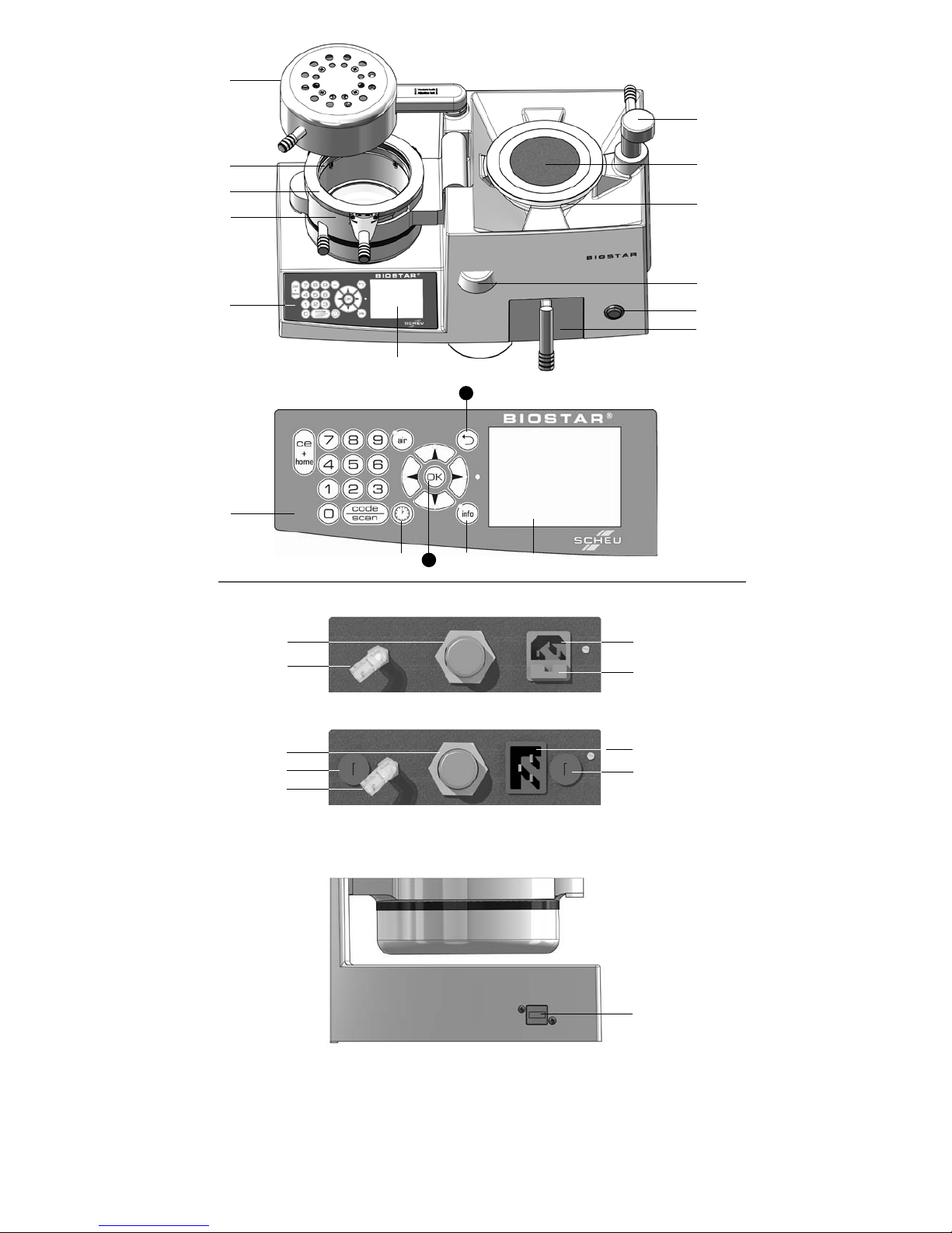
Whenusinghardorhard-elasticmaterial,modelsareplacedintothemodelcup4,lleduptoitsupperrimwithstainlesssteelpellets.Whenus-
ing soft elastic material, models can be placed on the working platform 6.In both cases, the model should be placed with the incisors facing to the
right towards the locking handle 3or to the left towards the pressure chamber 2toensureequalthicknessofthematerialbetweenthequadrants.
11. Scanning/programming by setting code or time
Ourpressuremouldingmaterialhasa3-digit-codewhereallrequiredinformationontemperature,heatingtimeandcoolingtimeisprogrammed.This
code is printed in plain text and as bar code on our pressure moulding blanks or foils, except for material with thicknesses below 0.1 and 0.15 mm.
After selecting your material, press the button „code/scan“.
The scanner Pisnowactivated.Presentonlynowthebarcodeofthechosenmaterialtothescanneruntilyouhearabeep.Alternatively,thecode
can be programmed manually.
Programthedigitsandconrmbypressingthebutton„code/scan“again.Youeitherhavetheoptiontoentertheheatingtimesmanually.Doingso,
press the key with the clock symbol Q,entertherequiredheatingtimeandconrmbypressingthebuttonQagain.
12. Heating
After programming, directly swivel the infrared heater 1over the fixed material. The temperature is regulated automatically by a thermo element.
The colour of the heater might vary from bright to dark.
13. Pressurising
Beforetheendoftheheatingcycleisreached,audiblebeepingsoundsareheard(+5sec.upto0sec.=beepingsounds/0sec.upto5sec.con-
tinuousbeepingsound).Theheatershouldbeswivelledbackat0sec.,at-5sec.theheaterisswitchedoffautomaticallyforsafetyreasons.Bring
the pressure chamber 2over the model by turning it 180° to the right (make sure the sealing surface is clean) and lock it into place by turning
the locking handle C180° forwards. Automatically the magnetic valve opens, the pressure chamber fills with air and the cooling time starts, signal
byblueLED.
14. Depressurising
Opticalsignals(blueashingLED)andacousticsignals(4beepingsounds)indicatethecoolingtimehaselapsed.Presstheashingbutton„air“ to de-
pressurise the pressure chamber.After approx. 3 seconds 4 beeping sounds indicate the end of depressurising.Now turn the locking handle 3180°
backwards, push the locking ring K to the left and open the pressure chamber 2. Remove the model. The machine can now be used for
the next pressure moulding operation.
15. Special programs using the heating support
Ifyouwanttofabricatepositioners,mouthguardsorsplints,youcanmanuallyprogrammetimeintervalsof60/120/180/240seconds.Doingso,the
pressure chamber has to be closed and the locking handle opened. These intervals are chosen to heat up or to seal the occlusal surfaces using the
heatingsupport.(REF3452).Afterhavingenteredthecorrespondingheatingtime,theinfraredheaterwiththeheatingsupporthookedinisswivelled
forwardsintheheatingposition.Dependingonthematerialthickness,thisoperationcanberepeatedseveraltimes.
16. Service/Maintenance
TheBIOSTAR®machine is maintenance free. However, the air tube including the filter element should be examined regularly. If moisture or debris
is released, the filter must be replaced. The model cup 4with air holes and model platform 6can be cleaned with an air nozzle or steam jet. The
reflecting parts of the pressure chamber should be cleaned regularly to obtain the best heating results. For cleaning remove the aluminium adjusting
ring Lfrom the pressure chamber 2completely. The sealing surfaces, the sealing ring and the 4 rivets and springs should be cleaned and lightly
greasedalso.Placetheadjustingringbackontherivetsandspringsensuringthatthesealingringcomestothetopandthatthewholeunitismovable.
Pleasealsorefertotheenclosed„Guidelinetosolvetechnicalproblems“.
17. Service updates
You‘llreceivearegistrationcardwiththemachine.Bysigning-up,you‘llbeprovidedautomaticallywithinformationonupdates.Youcandownloadthe
updates on our website www.scheu-dental.com/downloads/support.
ExtracttheletoanemptyandformattedremovableUSBdevice.ConnecttheUSBdevicetothetheservice interface Son the back of the machine.
Start the machine, then press 5 times the button „OK“. Now you‘ll be asked to enter the pass word for the service menu.
Enterthefigure „1“ and confirm by pressing the button „OK“.Bypressingaginthefigure „1”theupdatestarts.Aftertheupdateisnished,quit
the service menu by pressing the button „CE+home“.
Technical modification, which serve for improvement, are subject to our agreement. Reproduction, even in extracts, is only allowed with our written approval.

F
Français
1. Consignes de sécurité générales
Avantlamiseenserviceetlebranchementdel‘appareil,lireattentivementetdansleurintégralitélemoded‘emploiainsiquecesremarquesimpor-
tantesets‘assurerquelesconditionspréalablessontremplies.
Remarques générales
• Contrôlerleparfaitétatdel‘appareilavantsamiseenservice.Encasdedommage,ilestinterditdelemettreenservice.
• Toujourssurveillerl‘appareillorsqu‘ilestsoustension.
• Utiliseruniquementdesplaques/feuillesd‘undiamètrede125mm!
• Faireattentionquel‘appareilsoithorsdeportéedesenfants.
• Evitertoutcontactaveclesliquidespourexclurelerisquedechocélectrique.
• Larésistanceetlebrasdelarésistancedeviennenttrèschauds.
• Faitesattentionàcequ‘iln‘yaitpasdematériauxinammablesendessousouprèslalampeàinfrarouge!
• Nemanipulerqu‘aveclespoignées.Risquedebrulûre!
• Pourletransport,l‘appareildoitêtrerefroidi.
• Lorsdutransport,faitesattentionàcequelarésistancesoitaccessiblepourévitertoutendommagement.
• Unemanipulationdel‘appareilsansrisquenepeutêtregarantiqu‘enutilisantlespiècesdétachéesoriginalesdeSCHEU-DENTAL.Toujoursfaire
réaliser les travaux par des techniciens de service après-vente qualiés agréés par SCHEU-DENTAL ou directement chez SCHEU-DENTAL.
Unemodicationouunetransformationdel‘appareilcomprometlasécuritéduproduitetpeutentrainerl‘annulationdelagarantie.
• Nejamaisouvrirl‘appareildesapropreinitiative!Attention, risque de blessure!
• Nejamaiseffectuerlesréparationssoi-même!
• L‘appareilestconçupourdesréseauxélectriquesavecunetensionalternativede100V,115Vou230V.
(seconformerauxinformationsportéessurl‘étiquetteaveclenumérodesérieaudosdel‘appareil).
Installation de l‘alimentation électrique sur site
L‘installationdel‘alimentationélectriquepourlebranchementdenosappareilsdoitimpérativementêtreeffectuéeconformémentauxprescriptions
internationalesetauxdispositionsquiontdécoulent.
Nos appareils sont construits conformément à la classe de protection I selon VDE et doivent impérativement être branchés sur une
prise à contact de protection.
Environnement
L‘appareilestfabriquéàpartirdesmatériauxréutilisablesourecyclables.Conformémentàladirectiverelativeauxdéchetsd‘équipementsélectriques
etélectroniques(DEEE)2012/19SCHEU-DENTALacceptedereprendrel‘appareilsousréservequeleretourestpayéparl‘expéditeur.Alternative-
ment,l‘appareilpeutêtreenvoyéàunedéchargespécialiséepourlarécupérationetlerecyclagedesappareilsélectriquesouélectroniques.
2. Mise en service générale
Ilestimportantdelireetsuivrelesinstructionssuivantespourobtenirdesrésultatsdethermoformageoptimum.Mettreenplacel‘appareil
BIOSTAR®defaçonquelarésistance1, la chambre de pression Bet l‘arbre de serrage Csoientàtoutmomentaccessibles.
Eviterdeplacerl‘appareilàproximitédesappareilsdenettoyageaujetdesableoudevapeur.Verserlesgranulésinoxjointsdanslacuveàmodèle
Det le reste dans le tiroir E;enutilisantlaplaqueporeuseFfaitesattentionàcequelasurfacedelaplaqueporeusedanslacuveàmodèle
soitlibredesgranulés.Lessurfacesau-dessusetendessousdelacuveàmodèledoiventégalementêtrelibresdegranuléspendantleprocédéde
thermoformage.Utiliseruniquementlesgranulésjointspourenroberlesmodèles!
D‘autresmatériaux(commep.ex.durizoudusable)risquentd‘endommagerlespiècespneumatiquesetlestrouspourl‘évacuationdel‘air.
L‘aircompimépendantlethermoformageainsiquependantladécompressionpourraitfairetourbillonerlesgranulésd‘unmatériaupluslégerqueles
granulésinox.Utiliseruniquementlecâbleélectriqueetletuyauàl‘aircompriméd‘originefournis;l‘aircomprimédoitêtreexemptd‘huileethumidité.
Lapressionminimalepourfairefonctionnerl‘appareilBIOSTAR®est de 6 bar.
3. Configuration
Modiezl‘afchagedelalangue,presssion,températureetlecontrastedel‘écranselonvosbesoins.
Brancher l’appareil
Presserlatouche„CE+home“5foisquandl‘écranmontrelaversionactuelledel‘appareil.
Sélection de la langue
Choisissezlechiffre–conrmezenappuyantlatouche„code/scan“
Sélection de la pression
Choisissezlechiffre–conrmezenappuyantlatouche„code /scan“
Sélection de la température
Choisissezlechiffre–conrmezenappuyantsurlatouche„code/scan“
Sélection du contraste de l‘écran
Choisissezlechiffre–conrmezenappuyantsurlatouche„code/scan“

F
Français
4. Menu info
Danslemenuinfolesinformationssuivantessontdisponibles:
Logiciel : Affichage de la version installée
Consignes de sécurité :Voustrouverezicidesconsignesimportantespouruneutilisationsûredevotreappareildethermoformage.
Indications :Découvreztoutelagammedethermoformagedansuneversiondigitaledenotremanueldethermoformage.
Mesures pour remédier aux petits dérangements : Trouvez des solutions simples et rapides aux troubles pendant le procédé de thermoformage
Gamme des matériaux de thermoformage :Obtenezunaperçudelavastegammedematériauxdethermoformageetdesinformationssur
chaqueplaque.
Vidéos :Rafraichissezvosconnaissancesdefaçonsimpleetconfortableenregardantnoscourtsvidéossurlafabricationdesgouttièresdifférentes
thermoformées.
Aprèslamiseenservicedel‘appareil,lamenuinfoestaccessibleenappuyantsurlatouche„info“ T,l‘appareilétantenpositiondebase(voirsvpp.7).
Vous pouvez naviguer avec les touches suivantes:
LesLEDdestouchesvoussignalisentladisponibilitédesinformations.
Touche info T :Appel du menu info:
Astuce!
Aprèsavoirscannéuneplaque,uniquementlesinformationsspéciquesdecetteplaqueserontdisponibles.Pendantleprocédé
dethermoformage(chauffage,thermoformage,refroidissement)lemenuinfon‘estpasaccessible.Lesinformationsetinstructions
concernantleprocédédethermoformagesontprioritairesetapparaissentdèsquelarésistance,lachambredepressionetl‘arbre
de serrage ne se trouvent plus dans la position de base.
Touches r et R:
Lestouchesdenavigationhorizontalesnesontdisponiblesqu‘aprèsavoirappeléune„indication“etvouspermettentdenaviguer
directement entre les indications différentes.
Touche OK
22
: Conrmationdelasélection.
Touches qetQ: Les touches de navigation verticales vous guident dans le menu actuel.
Touche
21
: Enappuyantsurlebouton retourvouspouvezreveniràlasélectionprécédente.
Touche CE+home :
Latouchevouspermetdereveniràl‘afchage:„Sélectiondumatériauselonindication“.
5. Raccordement au reseau
Brancherl‘appareilBIOSTAR®auréseaucorrespondant(voirsvpraccordementauréseaudanslesconsignesdesécurité)àl‘aideducâblefournià
la prise au courant 7audosdel‘appareil.Pourlesmodèlesen220V,ilyadeuxfusiblesminiaturesdanslapriseaucourantaudosdel‘appareil
protégeantl‘électroniquecontrelasurtension.Pourleschanger(sinécessaire)presserlapetiteagrafeen-dessousdelapriseaucourantetenlever
les fusibles 8.Pourlesmodèlesen100/115VcesdeuxfusiblessetrouventdansdeuxsupportsRséparésquevouspouvezdévisser.
6. Raccordement à l‘air comprimé
Untuyauà20bar9avecltreestconnectédefaçonxeavecl‘appareiletnedevraitpasêtreéchangé.Brancherl‘appareilBIOSTAR®àvotreréseau
d‘aircomprimé.Utiliserletuyauen20bar,ouunraccordrapideouàvis.Lapressiondetravailde6,0bar/87psi(régléedépartusine)estindiquée
defaçoncontinuesurl‘écranetnedevraitpasêtrechangée.Elleestoptimiséeandegarantirlesmeilleursrésultats.Sitoutdemêmeuneréduction
delapressionestdésirée,ellepeutêtrerégléeàl‘aidedurégulateurdepressionJau dos de l‘appareil. Avant de tourner le régulateur, tirer le afin
deledéverrouiller( ). Ajuster le régulateur en le tournant et presser afin de le verrouiller de nouveau.
Encasd‘uneaugmentationdelapressionau-delàde6,5bar/94psi(cequinecorrespondpasànosrecommendations),lavalvedesécuritéestmise
enaction(bruitd‘évacuationd‘air).
7. Position de base
La résistance 1pivotéeversl‘arrièrejusqu‘àlabutée,lachambredepression2ouverte vers la gauche, l‘arbre de serrage 3pivotéeversl‘arrière
jusqu‘àlabutée(position12heures).Voirgure1.
8. Mise en service
Enappuyantsurl‘interrupteurmarche/arrêt
M
,unmodedecontrôleetd‘ajustagede10sec.estmisenmarche.Aprèscela,l‘écranafcheledia-
loguestandard,étantlepointdedépartpourtouteslesfonctionsdethermoformage.Laprogrammations‘effectueàl‘aideduclavier
O
ou le scanner
P
etestindiquéesurl‘écran
N
.
9. Mise en place des plaques
L‘appareilBIOSTAR®utilisetouteslesplaquesetfeuillesrondesd‘undiamètrede125mmpourdesépaisseursde0,1à5,0mm.Andexerles
plaques,ouvrirlachambredepression2enpivotantsurlagauche.EnleverlecercledeserrageKenleplaçantà5heures.Poserlaplaqueou
feuille directement sur le joint du cercle d‘ajustement Ldans la chambre de pression ouverte. Vérouiller en mettant en place le cercle de serrage
enletournantà6heures.

F
Français
10. Préparation des modèles
Enutilisantlesplaquesoufeuillesduresetdures-élastiquesplacerlesmodèlesdanslacuveàmodèle4,rempliedesgranulésjusqu‘aubord
supérieur.Enutilisantlesfeuillesmolles-élastiquesplacerlesmodèlessurlaplaqueporeuse6.Danstouslescaslesincisivesdevraientêtreposi-
tionnées vers le bras de fermeture 3àdroiteouàgaucheverslachambredepression2,and‘éviterdesépaisseursinégalesdelaplaqueaprès
le thermoformage.
11. Scanning/Programmation
Pourtoutesnosplaquesdethermoformageilyauncodecomposéde3chiffrescontenanttouteslesinformationsdetempérature,letempsde
chauffeetderefroidissement.Voustrouverezcecodesurtoutesnosfeuillesetplaquesdethermoformage(àl‘exceptiondesfeuillesd‘uneépaisseur
inférieurà0,1mmet0,15mm)enchiffreetencodedebarre.Aprèsavoirchoisilaplaqueappuyezsur„code/scan“.
Le scanner Pestactivé.Tenezlecodebarredelaplaquechoisiesouslescanner,jusqu‘àcequ‘ilyaitunsignalsonore.Biensûr,vouspouveztou-
joursentrerlecodedefaçonmanuelle.Danscecas-là,entrezleschiffresetconrmezenappuyantsur„code/scan“.Enoutre,vousavezlapossibilité
d‘entrer manuellement les temps de chauffe. Appuyez sur le symbole de montre Q, entrez le temps de chauffe désiré et confirmez en appuyant de
nouveau sur la touche Q.
12. Chauffage
Aprèslaprogrammationpivotezlarésistance1surlaplaque/feuillexée.Latempératureestrégléeautomatiquementparunélémentthermocouple.
Ceteffetdevientapparentparl‘intensitédelumièrequivarie.
13. Thermoformage
Dessignauxsonoresannoncentlandutempsdechauffeavantqu‘ilnesoitécoulé(+5sec.à0sec.=signauxsonoresintermittents/0sec.
à-5sec.=signauxsonorespermanents).
A0sec.larésistancedevraitêtrepivotéeenarrière,à-5sec.larésistances‘éteintautomatiquementpourdesraisonsdesécurité.Pivoterlachambre
de pression 2vers la droite de 180° (faites attention à ce que les surfaces d‘étancheité soient propres) et tourner l‘arbre de serrage 3de
180°enavant.Lachambredepressionseremplied‘aircompriméetletempsderefroidissementdémarreautomatiquement(cequiestsignalisé
paruneLEDbleue).
14. Décompression
Lessignauxoptiques(LEDbleueclignotante)etsonores(4signauxsonores)indiquentlanduprocédéderefroidissement.Appuyezsurlatouchecli-
gnotante „air“pourladécompressiondelachambredepression,4autressignauxsonoresaprèsenviron3secondesannoncentlanduprocédéde
décompression.Tournez l‘arbre de serrage 3de180°enarrière,pousserlecercledeserrageK àgaucheetouvrirlachambredepression2.
Aprèsavoirenlevélemodèle,l‘appareilestprêtàdémarrerunnouveauprocédédethermoformage.
15. Programmes spécifiques en utilisant le support de chauffe
Sivousvoulezfabriquerdespositionneurs,desprotège-dentsoudesgouttières,vouspouvezprogrammerdesintervallesdetempsde60/120/180/240
secondes.Pourcela,lachambredepressiondoitêtreferméeetl‘arbredeserrageouvert.Cesintervallesdetempsserventauchauffageouaucollage
dessurfacesocclusalesenutilisantlesupportdechauffe(REF3452).Aprèsavoirentréletempsdechauffecorrespondant,larésistanceavecle
supportaccrochéestpivotéeenavantdanslapositiondechauffage.Ceprocédépeutêtrerépétéplusieursfoisselonl‘épaisseurdematériau.
16. Service après-vente/entretien
Enprincipe,l‘appareilBIOSTAR®estsansentretien.Vérierrégulièrementletuyauàl‘aircompriméavecleltre.Aucasoùilyauraitdesrésidus
d‘huileoudel‘humidité,ilestrecommandédelechanger.Nettoyerlacuveàmodèle4etlaplaqueporeuse6àl‘aided‘unebused‘airoud‘un
appareildenettoyageaujetdevapeur.Pourunechauffeoptimaledesplaquesilestindispensablequelasurfacereéchissantedanslachambrede
pression soit propre. Afin de nettoyer le cercle en aluminium Ldans la chambre de pression 2 peutêtreenlevécomplètement.Nettoyeretgraisser
lessurfacesd‘étanchéité,lejointlatéraletles4rivetsetressorts.Replacerlecercled‘aluminiumsurlesrivetsetressortsdefaçonquelejointsoit
verslehautetquel‘ensembleducerclerestemobile(voirsvpégalementlesastucespourrémedierauxpetitsdérangements).
17. Mises à jour service
Vousrecevezuneched‘enregistrementavecl‘appareil.Sivousvoulezvousenregistrer,vousserezinformésautomatiquementsurlesmisesàjour.
Vouspouveztéléchargerlesmisesàjoursurnotresiteinternet„www.scheu-dental.com/téléchargements/support“.Extrairelechiersuruneclé
USBvideetformatée.Connectezlaclé USB Saudosdel‘appareil.Démarrezl‘appareiletappuyez5foissurlatouche „OK“.
Vousserezinvitésàentrerlemotdepassepourlemenudeservice.Entrezlechiffre „1“ et confirmez en pressant sur „OK“.Lamiseàjourestdemar-
rée en appuyant de nouveau sur le chiffre „1“.Lamiseàjourécoulée,vouspouvezquitterlemenuserviceenappuyantsurlatouche „CE+home“.
Sousréservedemodicationstechniquesvisantàaméliorernosproduits.Reproductionuniquementsurnotreautorisationenécrit(égalementextraits).

E
Español
1. Instrucciones de seguridad
Antes de la puesta en funcionamiento y la conexión del aparato, lea con atención las instrucciones de uso, así como estas importantes indicaciones,
yasegúresedequesecumplenlosrequisitosestablecidos.
Instrucciones generales
• Antesdelapuestaenfuncionamientodelaparato,compruebequenopresentadeterioros.Encasodepresentaralgúndeterioro,nopongael
aparato en servicio.
• Supervisesiempreelaparatocuandoestéconectado.
• UtilicesololáminasdeØ125mm.
• Evitequelosniñostenganaccesoalaparato.
• Elaparatonodebeentrarencontactoconlíquidosconelndeevitardescargaseléctricas.
• Lalámparayelbrazodelalámparaalcanzantemperaturaselevadas.
• Noutiliceelaparatocercadematerialesfácilmenteinamables.
• Manipuleelaparatoutilizandoexclusivamentelosmangosprevistosalefecto,yaquedelocontrarioexisteriesgodequemaduras.
• Elaparatosolodebesertransportadoestandofrío.
• Duranteeltransportelalámparanodebesoportarcarga.
• SolosepuedegarantizarunusosegurodelaparatosiseutilizanlaspiezasderecambiooriginalesdeSCHEU-DENTAL.
LostrabajosdemantenimientosolodebenserrealizadosporlostécnicoscualicadosdeserviciodeSCHEU-DENTAL
oenlafábricadeSCHEU-DENTAL.
La manipulación o modificación del aparato merma la seguridad del producto y es causa de extinción de los derechos de la garantía.
• Nuncaabraelaparatoporcuentapropia.Atención: riesgo de lesiones.
• Nuncarealicereparacionesenelaparatoporcuentapropia.
• Elaparatoestápreparadopararedeseléctricasdetensiónalternade100V,115Vo230V.(Porfavor,consulteaesterespectolaetiquetaconel
númerodeseriequeencontraráenelreversodelaparato).
Instalación del suministro de corriente local
Lainstalacióndelaalimentaciónderedparalaconexióndenuestrosaparatosdebecumplirconlasnormasinternacionalesylasdisposicionesque
deriven de ellas.
Nuestros aparatos están fabricados conforme a la clase I de protección de la VDE (Asociación alemana de electrotécnicos) y deben
estar conectados a una toma con puesta a tierra.
Medio ambiente
Elaparatosehafabricadoconmaterialesreutilizablesoreciclables.Conformealadirectivasobreresiduosdeaparatoseléctricosyelectrónicos
2012/19/UE,SCHEU-DENTALaceptaladevoluciónvoluntariadelaparatodeformagratuita.Cabetambiénlaposibilidaddeentregarlosaparatos
eléctricos y electrónicos en un punto de recogida para su reciclaje.
2. Puesta en funcionamiento general
EsprecisoleeryseguirlassiguientesindicacionesparaobtenerunaprovechamientoóptimodeBIOSTAR®.
Porfavor,coloqueelaparatoBIOSTAR®detalformaquelalámparadeinfrarrojos1,lacámaradepresión2yelejedebloqueo3se puedan
mover libremente. Se debe evitar la cercanía de vaporizadores y arenadoras, así como la colocación en lugares con gran acumulación de yeso o polvo.
Porfavor,viertaelgranuladodeaceroinoxidablesuministradoenelrecipientedelmodelo4y la cantidad restante en el cajón 5; cuando utilice
la plataforma del modelo 6asegúresedequenohaygranuladoenlazonadeapoyodelaplataformasituadaenelrecipientedelmodelo.Durantela
embutición tampoco debe haber granulado de acero fino en las zonas de apoyo sobre y bajo el recipiente del modelo.
Porfavor,recuerdequenoesconvenienteusarotrosmateriales(p.ej.,arrozoarena)paralapuestaenrevestimientodelosmodelosyaque,entre
otrasrazones,laturbulenciageneradaporelaumentodepresiónylapurgadeairepuededeteriorarlaspiezasneumáticasylasaberturasdeaire
desalida,ynoposeenelpesonecesarioparaunacoberturaypuestaenrevestimientoprecisasdelosmodelos.Porfavor,utilicesiemprenuestras
conexiones de red y de aire originales; la red utilizada para el compresor o el aire comprimido no debe contener residuos de aceite ni humedad y debe
alcanzar una presión de transporte de al menos 6,0 bar.
3. Ajustes del sistema
Ajuste conforme a sus necesidades la visualización del idioma, presión, temperatura y contraste de pantalla.
Conexión del aparato
Enlasegundapantalla(indicacióndelaversióndelaparato)pulse5veceslatecla"CE+home".
Selección del idioma
Elijaunnúmero.Conrmeconlatecla"code/scan".
Selección de la presión
Elijaunnúmero.Conrmeconlatecla"code/scan".
Selección de la temperatura
Elijaunnúmero.Conrmeconlatecla"code/scan".
Contraste
Elijaunnúmero.Conrmeconlatecla"code/scan".

E
Español
4. Menú informativo
Enelmenúinformativopuedeaccederalasiguienteinformación:
Software: Indicación de la versión instalada.
Instrucciones de seguridad:Enestecampoaparecendatosimportantesparaelusoymanejosegurodesuaparatodeembuticiónprofunda.
Indicaciones:Descubraladiversidaddelatécnicadeembuticiónprofundamediantelaversiónenformatodigitaldelfolletoparausuarios“Técnica
de embutición profunda”.
Medidas para la solución de errores:Descubrasolucionesrápidasycómodasalosfallosquesepuedanproducirduranteelprocesodetrabajo.
Surtido de láminas:Hágaseunaideageneralsobreelvariadosurtidodeláminasyobtengaindicacionesparacadalámina.
Vídeos:Refresquesusconocimientosdeformasencillaycómodamediantebrevesvídeossobreelprocesodefabricacióndelasmásdiversasférulasembutidas.
Trasencenderelaparato,quedebeestarcolocadoenla“posicióninicial”(v.punto7),puedeaccederalmenúinformativomediantelatecla“Info” T.
Se navega con las siguientes teclas:
LosLEDsenlasrespectivasteclasseñalanquéinformaciónestádisponible.
Tecla Info T:Acceso al menú informativo
Aviso:
Unavezhaescaneadounaláminasolopodráaccederalainformaciónespecícadelalámina.
Duranteelprocesodeembuticiónprofunda(calentamiento/embuticiónprofunda/enfriamiento)elmenúinformativonoestá
disponible y permanece oculto.
Lasindicacioneseinstruccionessobreelprocesodeembuticiónprofundatienenpreferenciaysemuestrancuandolalámpara,
lacámaradepresiónoelejedebloqueosemuevandelaposicióninicial.
Teclas
r y R :
Lasteclasdenavegaciónhorizontalsoloestándisponiblescuandoseaccedeauna“Indicación”,ylepermitenpasardirectamen-
te de una indicación a otra.
Tecla OK
22
: Conrmacióndelaelección.
Teclas qy Q: Mediantelasteclasdenavegaciónverticalsepuedeustedmoverporelmenúactual.
Tecla
21
: Mediantelatecla Retorno accede a la selección anterior.
Tecla CE+home: MediantelateclaCE+homevuelvealaviso:“Seleccióndelmaterialsegúnindicación”.
5. Conexión a la red
ConecteelaparatoBIOSTAR®alaredcorrespondiente(v.lainstalacióndelsuministrodecorrientelocalenlasinstruccionesdeseguridad)acoplando
el cable de alimentación suministrado a la toma de alimentación 7situada en la parte posterior del aparato. La versión de 230 V del aparato dispone
dedosfusiblesenlatomadealimentaciónqueprotegenelsistemaelectrónicofrenteasubidasdetensión.Encasodequeseanecesariocambiarlos,
pulseelpequeñocierresituadobajolatomadealimentaciónysaqueelcompartimentodelfusible8.Enlasversionesde100V/115Vlosfusibles
se encuentran en 2 sujeciones separadas Rquesepuedenatornillar.
6. Conexión de aire comprimido
Elaparatollevaconectadodeformasegurauntubodeaire9de20barconunelementodeltrado;estetubonodebecambiarse.Puedeconectar
elaparatoBIOSTAR®conelcorrespondientetubodeaireasureddeairecomprimidoatornillándoloobienmedianteunacoplamientorápido.Lapre-
sióndetrabajo,conguradadefábricaa6,0bar/87psi,semuestracontinuamenteenlapantallaynodeberíamodicarse,yaquesoloasísepuede
lograr un modelado óptimo. Sin embargo, si se desea realizar una reducción, se puede modificar la presión con el regulador de presión Jsituado en
laparteposteriordelaparato.Paradesbloquearygirarelreguladordepresiónsedebetirardeél( ).Elreguladordepresiónsedebevolver
abloquearpresionandosobreél.Encasodeque,encontradenuestrasespecicaciones,seaumentelapresiónporencimade6,5bar/94psi,la
válvuladeseguridadseponeenfuncionamientoemitiendounfuerteruidodeexpulsióndeaire.
7. Posición inicial
Lalámpara1estágiradahaciaatráshastaeltope,lacámaradepresión2estáabiertahacialaizquierda,elmangodelejedebloqueo3está
giradohaciaatráshastaeltope(12horas)(v.g.1).
8. Conexión
Elaparatoseponeenfuncionamientomedianteuninterruptordeencendido/apagadoM, ejecuta durante aprox. 10 s un modo de comprobación y
ajusteyacontinuaciónmuestraelcuadrodediálogoestándar,elpuntobásicodepartidadelosprocesosdeembuticiónprofunda.Laprogramaciónse
realiza a través del teclado O
oelescáner
P
y se indica en la pantalla
N
.
9. Tensionamiento de las placas
EnBIOSTAR®sepuedenutilizartodaslasplacasyláminasredondasconundiámetrode125mmyungrosordesde0,1mmhasta5,0mm.Paratensarlas,abra
lacámaradepresión2girándolahacialaparteizquierdayextraigaelanillodecierreKgirandoelmangohastalaposicióndelas5horas.Coloquelaláminaso-
bre la junta del anillo de compensación Lvisibleenlacámaradepresiónyfíjelacolocandoelanillodecierreygirandoelmangohastalaposicióndelas6horas.

E
Español
10. Preparación del modelo
Siseutilizanláminasyplacasdurasyduro-elásticas,losmodelossecolocanenelrecipientedelmodelo4, lleno de granulado hasta el borde su-
perior.Enelcasodeláminasblando-elásticassepuedencolocarlosmodelosenlaplataformadelmodelo6.Enamboscasoslosdientesincisivos
debenestarorientadoshaciaelejedebloqueo3,aladerechaohacialacámaradepresión2,alaizquierdaparaevitarquetraselmodelado
aparezcandiferenciasdegrosordeláminaentreloscuadrantes.
11. Programación mediante escáner o código e introducción del tiempo
Todosnuestrosmaterialesdeembuticiónprofundatienenasignadouncódigode3cifrasquecontienetodalainformaciónimportantesobretempera-
turaytiemposdecalentamientoydeenfriamiento.Estecódigoestáimpresoenformatodetextoycomocódigodebarrasentodoslosmaterialesde
embuticiónprofundaexceptoenlosmaterialesde0,1mmy0,15mmdegrosor.Trasseleccionarelmaterialrequerido,pulselatecla“code/scan”.El
escáner
P
sehaactivado.Coloqueahorabajoelescánerelcódigodebarrasdelmaterialdeembuticiónprofundaseleccionadohastaquesueneuna
señalacústica.Deformaalternativaalescánersepuedeintroducirelcódigomanualmente.Introduzcalascifrasyconrmepulsandodenuevolatecla
“code/scan”.Tambiénsepuedenintroducirmanualmentelostiemposdecalentamiento.Pulselateclaconeliconodelreloj
Q
, introduzca el tiempo
de calentamiento deseado y confirme el tiempo introducido pulsando de nuevo la tecla
Q
.
12. Calentamiento
Inmediatamentedespuésdeprogramarelaparato,girelalámpara1hastacolocarlasobrelaláminatensada.Latemperaturaseregulaautomáti-
camentemedianteunelementotérmico,efectoquesepuedeidenticarporelcambiodecolordelaluz.
13. Embutición profunda
Lasseñalesacústicasindicanelnaldelprocesodecalentamiento(+5shasta0s=pitidos/0shasta-5s=sonidocontinuo).En“0s”lalámpara
deberegresarasuposicióninicial,yen“-5s”lalámparaseapagapormotivosdeseguridad.Girelacámaradepresión2180° hacia la derecha
(asegúrese de que la superficie de contacto esté limpia) yelejedebloqueo3180°haciadelante.Deestaformaseventilalacámaradepresión
ycomienzaautomáticamenteeltiempodeenfriado;comoseñalseenciendeelLEDazul.
14. Purga de aire
Lasseñalesópticas(LEDazulintermitente)yacústicas(4pitidos)indicanelnaldelprocesodeenfriado.Alpulsarlateclaintermitente“air”, la
cámaradepresiónsepurgadeaireytrasaprox.3segundosotras4señalesacústicasindicanelnaldelprocesodepurgadodeaire.Ahoragireel
ejedebloqueo3180°haciaatrás,desplaceelanillodecierreK hacialaizquierdayabralacámaradepresión2 . Tras la extracción
delmodelo,elaparatoestálistodenuevoparaelsiguienteprocesodeembuticiónprofunda.
15. Programas especiales para apoyo del calentamiento
Conlacámaradepresióncerradayelejedebloqueoabiertosepuedenprogramarintervalosde60/120/180/240segundosparalafabricaciónde
posicionadores,protectoresbucalesoférulas.Estosintervalospermitenelcalentamientoolaunióndesuperciesoclusalesconayudadelsoporte
decalentamiento(REF3452).Traslaprogramacióndeltiempodecalentamientocorrespondientesegiralalámparahaciadelante,conelsoportede
calentamientojadoaella,hastalaposicióndecalentamiento.Dependiendodelgrosordelmaterialesposiblerealizaresteprocesovariasveces.
16. Servicio técnico/Mantenimiento
EnprincipioelaparatoBIOSTAR®norequieremantenimiento.Únicamentedebecomprobarperiódicamentequenohayasedimentosnihumedaden
eltubodeaire,incluidoelelementodeltrado.Encasonecesariosepuedecambiarelltro.Elrecipientedelmodelo4con orificios de aire de salida
y la plataforma del modelo 6puedenlimpiarseconunaboquilladeaireounvaporizador.Lassuperciesdereexióndelacámaradepresióndeben
estarlimpiasparapoderobteneruncalentamientoóptimodelasláminas.Pararealizarlalimpiezasepuederetirar,ladeándolo,elanillodecompen-
sación de aluminio Ldelacámaradepresión2. Limpie y engrase las superficies de contacto, la junta lateral y los 4 remaches y muelles. Vuelva
acolocarelanillodecompensaciónsobrelosmuellesyremachesdetalformaquelajuntaestéorientadahaciaarribayquelaunidadcompletase
puedamoversinobstáculos(véansetambiénlasmedidasparasolucióndeerrores).
17. Actualizaciones de servicio
Juntoconelaparatosesuministraunatarjetaderegistro.Siseregistra,recibiráautomáticamenteinformaciónsobrelasactualizaciones.Ennuestra
páginaweb“https://www.scheu-dental.com/downloads/support” puede descargar las actualizaciones.
ExtraigalosdatosdedescargaaunamemoriaUSBvacíayformateada.AcontinuaciónlamemoriaUSBsepuedeintroducirenlainterfaz de servicio S
ubicada en la parte posterior del aparato.
Pongaelaparatoenmarchayacontinuaciónpulse5veceslatecla “OK”.Aparecerálapantalladeintroduccióndelacontraseñaparaelmenúde
servicio.Porfavor,introduzcaelnúmero “1” y confirme pulsando la tecla “OK”.Pulsedenuevoelnúmero “1”yseiniciarálaactualización.Una
vez finalizada la actualización, abandone el menú de servicio pulsando la tecla “CE+home”.
Nosreservamoselderechoaintroducirmodicacionestécnicasquesuponganunamejora.Lareproducción,completaoparcial,estápermitidasolo
con nuestra autorización por escrito.

I
Italy
1. Indicazioni di sicurezza
Primadimettereinfunzioneecollegarel'apparecchio,leggereattentamenteleistruzioniperl'usoelepresentiimportantiavvertenze,vericando
cheirequisitispecicatisianosoddisfatti.
Indicazioni generali
Primadellamessainfunzione,vericarechel'apparecchiononpresentidanni.Qualorarisultidanneggiato,nonmettereinfunzionel'apparecchio.
• L'apparecchioaccesodevesempreesseresorvegliato.
• UtilizzareunicamentedischiconØ125mm!
• Tenerel'apparecchiolontanodallaportatadeibambini.
• Perevitarescosseelettriche,questoapparecchionondeveentrareincontattoconliquidi.
• Lalampadaeilrispettivobraccioraggiungonotemperatureelevate.
• Nonutilizzarenellevicinanzedimaterialifacilmenteinammabili.
• Utilizzarel'apparecchioafferrandoesclusivamentelemaniglieprevistealloscopo;incasocontrario,vièilpericolodiustioni.
• L'apparecchiopuòesseretrasportatosolodafreddo.
• Trasportarel'apparecchiosoloinmododanonesercitarealcunasollecitazionesullalampada.
• Lasicurezzadiimpiegodell'apparecchiopuòesseregarantitaunicamenteconl'utilizzodipartidiricambioSCHEU-DENTALoriginali.
GliinterventidiassistenzadevonosempreessereeffettuatidauntecnicoSCHEU-DENTALqualicatoointernamenteaSCHEU-DENTALstessa.
Eventualimodicheoalterazionidell'apparecchiopossonocomprometternelasicurezzaedeterminarel'invaliditàdellagaranzialegaleedella
garanzia commerciale.
• Nonapriremail'apparecchiodipropriainiziativa.Attenzione Pericolo di lesioni!
• Noneseguiremaiautonomamenteriparazioni!
• L'apparecchioèprogettatoperl'usosuretielettrichecontensionealternatada100V,115Vo230V(attenersiaquantoriportatosull'etichetta
delnumerodiseriepostasulretrodell'apparecchio).
Installazione dell'alimentatore di corrente sul posto
L'installazionedell'alimentatoredireteperilcollegamentodeinostriapparecchideveessereeseguitaconformementeallenormativeinternazionalie
alle disposizioni da esse derivanti.
I nostri apparecchi sono costruiti secondo la classe di protezione VDE I e devono essere collegati a una presa dotata di conduttore
di protezione.
Ambiente
L'apparecchioèprodottoconmaterialiriutilizzabilioriciclabili.Aisensidelladirettiva2012/19/UEsuiriutidiapparecchiatureelettricheedelettro-
niche,SCHEU-DENTALritirasenzaalcuncostol'apparecchiousatoconmodalitàdirestituzionegratuita.Inalternativaessopuòessereconferitoaun
centro di raccolta per il riciclaggio di apparecchiature elettriche ed elettroniche.
2. Istruzioni generali per la messa in esercizio
Perl'utilizzoottimalediBIOSTAR®ènecessarioleggereerispettareleseguentiavvertenze.
Posizionarel'apparecchioBIOSTAR®in modo che la lampada IR 1, la camera di pressione 2el'alberodichiusura3non siano limitati nei loro
movimenti.Evitarelavicinanzadiapparecchiagettodivaporeosabbiatricieluoghidiinstallazioneconelevatocaricodipolveriogesso.
Versare il granulato di acciaio inox fornito nel contenitore portamodelli 4econservarelaquantitàrimanentenelcassetto5; in caso di impiego della
piastra portamodelli 6accertarsi che sulla superficie di appoggio della piastra portamodelli sul contenitore portamodelli non vi siano resti di granulato.
Anche le superfici di appoggio al di sopra e al di sotto del contenitore portamodelli devono essere prive di granulato di acciaio inox in ogni operazione di
termoformatura.
Sisconsiglial'impiegodiqualsiasialtromateriale(peres.risoosabbia)perlacollocazionedeimodelli,inquanto,tralealtrecose,perviadelle
turbolenze durante la messa in pressione e lo sfiato, tali materiali potrebbero danneggiare i componenti pneumatici e le aperture di aerazione e non
avereilpesonecessarioperl'esattacoperturaeperlacollocazionedeimodelli.Sipregaassolutamentediutilizzareinostriraccordioriginaliperil
collegamentoall'ariacompressaeallareteelettrica;laretedell'ariacompressaodelcompressoredeveessereprivadiresiduidiolioeumiditàe
raggiungere una pressione di mandata minima di 6,0 bar.
3. Impostazioni di sistema
Adeguare alle proprie esigenze la visualizzazione di lingua, pressione, temperatura e contrasto dello schermo.
Accensione apparecchio
Allacomparsadellasecondavisualizzazionesulloschermo(indicazionedellaversionedell'apparecchio),premere5xiltasto“CE+home”.
Selezione lingua
Selezionareilnumeroappropriato–Confermareconiltasto“code/scan”
Selezione pressione
Selezionareilnumeroappropriato–Confermareconiltasto“code/scan”
Selezione temperatura
Selezionareilnumeroappropriato–Confermareconiltasto“code/scan”
Contrasto
Selezionareilnumeroappropriato–Confermareconiltasto“code/scan”

I
Italy
4. Menu Info
Nel menu Info sono disponibili le seguenti informazioni:
Software: visualizzazione della versione installata.
Indicazioni di sicurezza:questocampofornisceimportantidirettiveperutilizzarelatermoformatriceinsicurezza.
Indicazioni:èquidisponibileunaunaversionedigitalizzatadell’opuscolopergliutenti“Tecnicaditermoformatura
”
perscoprirelaversatilitàdiquesta
tecnica.
Misure per l’eliminazione degli guasti: rapide e pratiche soluzioni per risolvere i possibili guasti che si verificano durante la lavorazione.
Assortimento dischi: una panoramica del ricco assortimento di dischi e avvertenze relative a ogni tipo di disco.
Video:perrinfrescareleproprieconoscenzeinmodosempliceepraticoconbrevivideoriguardantiilprocessodiproduzionedeipiùsvariatisplint
termoformati.
Coniltasto“Info
”
TèpossibilerichiamareilmenuInfodopol’avviodell’apparecchio,ilqualedovràesserein“posizioneiniziale
”
(ved.ilpunto7).
La navigazione è effettuata mediante i tasti seguenti:
ILEDdeicorrispondentitastisegnalanoquandosonodisponibiliinformazioni.
Tasto Info T:richiamo del menu Info
Attenzione!
Seègiàstataeffettuatalascansionediundiscooraèpossibilerichiamareunicamenteinformazionispecichedeldisco.
Duranteilprocessoditermoformatura(riscaldamento/termoformatura/raffreddamento)ilmenuInfononèdisponibileevienenascosto.
Leavvertenzeeleistruzioniriguardantiilprocessoditermoformaturahannolaprioritàevengonovisualizzatequantolalampada,
lacameradipressioneol’alberodichiusuravengonospostatidallaposizioneiniziale.
Tasti
r e R :
itastidinavigazioneorizzontalesonodisponibilisoloseèstatarichiamatauna“Indicazione
”
econsentonodinavigaretrale“Indicazioni
”
.
Tasto OK
22
:conferma della selezione
Tasti qe Q: itastidinavigazioneverticaliconsentonolanavigazioneall’internodelmenucorrente.
Tasto
21
: il tasto di ritorno consente di tornare alla selezione precedente
Tasto CE+home: con il tasto CE+homesiritornaallavisualizzazione:“Selezionedelmaterialeinbaseall’indicazione
”
5. Collegamento alla rete elettrica
Collegarel’apparecchioBIOSTAR®allareteelettrica(ved.Installazionedell’alimentatoredicorrentesulpostonelleIndicazionidisicurezza)inserendo
il cavo di rete nella presa di rete 7sulretrodell’apparecchio.Nellaversionedell’apparecchioa230Vnellapresadiretesitrovanoancheduefusibili
cheproteggonol’elettronicadell’apparecchiodallesovratensioni.Perl’eventualesostituzionepremerelapiccolaclipsottolapresadireteedestrarre
lo scomparto portafusibili 8.Nellaversionedell’apparecchioa100V/115Vifusibilisonocollocatiin2supportiseparatiR, facilmente svitabili.
6. Collegamento all’aria compressa
Untuboessibileperl’ariaa20bar9conelementoltranteècollegatoinmodopermanenteall’apparecchioenondeveesseresostituito.Collegare
l’apparecchioBIOSTAR®allapropriaretedell’ariacompressaconl’appositotuboessibile,asceltamedianteattaccorapidooadavvitamento.La
pressionediesercizioèimpostatadalcostruttorea6,0bar/87psi,vienecostantementevisualizzatasuldisplayenondeveesseremodicatapoiché
soloatalepressioneèpossibileottenerelamassimadenizionediformatura.Setuttaviasidesideraapportareunariduzione,lapressionepuòesseremodi-
ficata con il regolatore di pressione Jsituatosulretrodell’apparecchio.Tirareilregolatoredipressionepersbloccarloequindiruotarlo( ).Premere
ilregolatoredipressioneperbloccarlonuovamente.Qualoralapressione,contrariamenteallenostredisposizioni,aumentasseoltre6,5bar/94psi,
entra in funzione la valvola di sicurezza con un forte rumore di sfiato.
7. Posizione iniziale
Lampada 1ruotataversoilretronoall’arresto,cameradipressione2apertaribaltataasinistra,manigliadell’alberodichiusura3ruotata verso
ilretronoall’arresto(ore12)(ved.Fig.1).
8. Accensione
L’apparecchiovienemessoinfunzioneconl’interruttoreon/offM,quindiesegueperca.10secondilemodalitàditesteimpostazioneeinnevisualizza
lanestradidialogostandard,puntodipartenzaperiprocessiditermoformatura.LaprogrammazioneèeseguitatramitelatastieraO
oloscanner
P
e viene visualizzata nel display
N
.
9. Fissaggio delle lastre
InBIOSTAR®èpossibilelavoraretuttelelastrerotondeeidischiconundiametrodi125mmeunospessorecompresotra0,1mme5,0mm.Per
il serraggio, aprire la camera di pressione 2ruotandolasullatosinistroerimuoverel’anellodichiusuraKruotandolamanigliainposizioneore5.
Posizionareildiscosull’anelloditenutadell’anellodicompensazioneLvisibilenellacameradipressioneebloccarlocollocandol’anellodichiusura
e ruotando la maniglia in posizione ore 6.

I
Italy
10. Preparazione modelli
Perlelastreeidischiduriedelastici-duriimodellivengonocollocatinelcontenitoreportamodelli4riempito di granulato fino al bordo di tenuta
superiore.Peridischielasticiemorbidiimodellipossonoesserecollocatisullapiastraportamodelli6. In entrambi i casi i denti anteriori devono
essererivoltiversodestraindirezionedell’alberodichiusura3o verso sinistra in direzione della camera di pressione 2 per evitare dopo la formatura
diversispessorididischitraiquadranti.
11. Programmazione tramite scanner o codice oppure con immissione dei tempi
Aciascunodeinostrimaterialipertermoformaturaèassegnatouncodicedi3cifrechecontienetutteleinformazioniimportantiriguardoatempe-
ratura,tempodiriscaldamentoetempodiraffreddamento.Questocodiceèstampatocometestoinchiaroecomecodiceabarresututtiimateriali
pertermoformatura,fattaeccezioneperimaterialiconspessoredi0,1mme0,15mm.Dopoaversceltoilmaterialeènecessariopremereiltasto
“
code/scan”. Lo scanner
P
èoraattivatoSoloaquestopuntotenereilcodiceabarredelmaterialepertermoformaturasceltoaldisottodelloscan-
nernchénonvieneemessoilsegnaleacustico.Inalternativaallascansione,ilcodicepuòancheessereimmessomanualmente.Immetterelecifre
e confermare premendo nuovamente il tasto “code/scan”.Ancheitempidiriscaldamentopossonoessereimmessimanualmente.Premereiltasto
conilsimbolodell’orologio
Q
,immettereiltempodiriscaldamentodesideratoeconfermarel’immissionedeidatipremendonuovamenteiltasto
Q
.
12. Riscaldamento
Dopoavereffettuatolaprogrammazioneruotarelalampada1per portarla direttamente al di sopra del disco fissato. La temperatura viene automa-
ticamenteregolataattraversountermoelemento.Questoeffettoèriconoscibiledalcambiamentodicoloredellaluce.
13. Termoformatura
Segnaliacusticiindicanolanedelprocessodiriscaldamento(da+5secondia0secondi=segnaliacusticiintermittenti/da0secondia-5secondi=segnale
acusticocontinuo).A0secondilalampadadeveessereriorientataindietro,a-5secondilalampadasispegneautomaticamentepermotividisicurezza.Orien-
tare la camera di pressione 2di 180° verso destra (verificare che la superficie di tenuta sia pulita) eruotarel’alberodichiusura3di 180° in avanti. In
talmodolecameredipressionevengonoventilateeiltempodiraffreddamentoautomaticamenteavviato;segnalazionetramiteilLEDblu.
14. Sfiato
Segnalivisivi(ilLEDlampeggia)eacustici(4segnaliintermittenti)indicanolanedelprocessodiraffreddamento.Premendoiltasto
“
air
”
lampeg-
giantesisatalacameradipressione,4ulteriorisegnaliacusticidopocirca3secondiindicanolanedelprocessodisato.Oraruotarel’alberodi
chiusura 3di180°versoilretro,spingerel’anellodichiusuraK verso sinistra e aprire la camera di pressione 2.Dopolarimozionedel
modellol’apparecchioènuovamenteprontoperilsuccessivoprocessoditermoformatura.
15. Programma speciale per il supporto per il riscaldamento
Concameradipressionechiusaealberodichiusuraapertoèpossibilelaprogrammazionespeciale,perlarealizzazionedi
posizionatori, protettori
oraliosplint,diintervalliditempodi60/120/180/240secondi.Questitempiservonoalriscaldamentooall’unionedisuperciocclusaliconl’ausilio
delsupportoperilriscaldamento(COD.3452).Alterminedellaprogrammazionedeltempodiriscaldamentocorrispondente,lalampadaconsupporto
perilriscaldamentoagganciatovieneorientatainavantinellaposizionediriscaldamento.Inbaseallospessoredelmateriale,questaprocedurapuò
essereeseguitapiùvolte.
16. Assistenza/manutenzione
Fondamentalmentel’apparecchioBIOSTAR®nonnecessitadimanutenzione.Occorresolocontrollareregolarmentecheiltubodell’aria,elemento
ltranteincl.,nonpresentiincrostazioninésegnidiumidità.Senecessario,illtropuòesseresostituito.Ilcontenitoreportamodelli4con fori di
aerazione e la piastra portamodelli 6possonoesserepuliticongettod’ariaodivapore.Lesuperciriettentidellacameradipressionedevono
esserepuliteperconsentireilriscaldamentoottimaledeidischi.Perlapulizial’anellodicompensazioneinalluminioLnellacameradipressione2
puòessererimossoinclinandolo.Pulireeingrassarelesuperciditenuta,l’anelloditenutalaterale,i4rivettielemolle.Posizionarenuovamente
l’anellodicompensazionesuirivettiesullemolleinmodochel’anelloditenutasiarivoltoversol’altoel’unitàcompletapossamuoversiliberamente
(ved.anchelemisureperl’eliminazionedeiguasti).
17. Aggiornamenti del servizio
Insiemeconl’apparecchiosiriceveunaschedadiregistrazione.Secisiregistra,siverràautomaticamenteinformatiinmeritoagliaggiornamenti.
È possibile scaricare gli aggiornamenti dalla nostra pagina Internet
“
https://www.scheu-dental.com/downloads/support
”
.
EstrarreiledidownloadsuunsupportodimemoriaesternoUSBvuotoeformattato.IlsupportodimemoriaesternoUSBpotràquindiessereinserito
nell’appositainterfaccia Ssulretrodell’apparecchio.
Avviarel’apparecchioequindipremere5xiltasto
“
OK
”
.CompareilcampodiimmissionedellapasswordperilmenuAssistenza.Digitarela
cifra
“
1
”
econfermarel’immissioneconiltasto
“
OK
”
.Premendonuovamentelacifra
“
1
”
haavviol’aggiornamento.Alterminedelprocessodi
aggiornamento uscire dal menu Assistenza con il tasto
“
CE+home
”
.
Conriservadimodichetecnichenell’interessedelprogresso.Lariproduzione,anchesoloparziale,èconsentitaunicamenteconlanostraautorizzazionescritta.

ac
bd
Debido a una modificación técnica de seguridad, su máquina de termomoldeo posee un agujero de descom-
prensión.
Esteagujerosetaponaalcerrarlacámaradepresiónconlapalancadecierre.
La superficie de la guarnición negra de goma debe estar siempre un poco engra-
sadaparacerrarfácilmenteyevitareldesgastedelaguarnición.
Silaguarniciónestádesgastada,puedecambiarlafácilmentetirandodelsoporte
delcasquillo(BIOSTAR®).
Antes de colocar la nueva guarnición, engrasar la superficie lateral del exterior
(imagen4).
Ensukitdeaccesoriosencontraráentreotros:
3recambiosdeguarniciónBIOSTAR®guarnición10mm,REF3000.856ytam-
biénunbotepequeñodegrasaconunpincelparaelgranulado,REF3005.800
A causa di una modificazione tecnica di sicurezza, vostro apparecchio possa di un alessagio di decompressione.
Questo alessagio si chiude al chiudere la camera di pressione con il albero
di chiusura. La superficie della guarnizione nera di gomma si deve sempre
ingrassareunpòperchiuderefacilmenteeimpedireilconsumodellaguarnizione.
Semailaguarnizioneèconsumata,sipuòcambiarefacilmentetirandodallosoppor-
todellabuccola(BIOSTAR®).
Primadicollocarelanuovaguarnizione,ingrassarelasupercielateraleall’e-
sterno(immagine4).
Ilsuokitdiaccessorihafral’altro:
3 pezzi di ricambio di guarnizione
BIOSTAR
®
guarnizione10mm,REF3000.856
e
ancheunalattinadigrassoconunpennellopergranulato,REF3005.800
Auf Grund sicherheitsrelevanter technischer Änderung ist bei Ihrem Gerät die Druckkammer mit einer Entlüftungs-
bohrung ausgestattet.
DieEntlüftungsbohrungwirdbeimVerriegelndergeschlossenenDruckkammer
mit der Verschlusswelle abgedichtet.
BitteachtenSiedarauf,dassdieDichtächeimmereinwenigeingefettetist.
NursowerdeneinleichtesVerriegelnundeingeringerVerschleißderDichtung
gewährleistet.
EineverschlisseneDichtungkanndurcheinfachesHerausziehenausderHülsen-
halterungbeimBIOSTAR®getauscht werden.
VordemEinsetzeneinerneuenDichtungsolltenSieauchdieäußereSeitenäche
derDichtungeinfetten(Bild4).
InIhremZubehör-PaketndenSieunteranderem:
3ErsatzdichtungenBIOSTAR®10mm,REF3000.856undaucheinTöpfchenmit
entsprechendemFettsowieGranulatpinsel,REF3005.800
Due to a safety-related technical modification the pressure chamber of your pressure moulding machine has been
equipped with a drill for decompression.
Locking the closed pressure chamber by means of the shaft collar, will tighten
this decompression drilling. Please make sure the sealing surface is always
lubricated, in order to ensure easy locking and less wear of the sealing.
A worn sealing can be easily replaced by pulling it out from the bush support
(BIOSTAR®).
Before inserting a new sealing, please lubricate the exterior side of the sealing,
too(picture4).
Youraccessoriessetcontains3replacementsealsBIOSTAR®10 mm sealing,
REF3000.856andsiliconegreaseaswellaspelletbrush,REF3005.800
Dû à une modification technique liée à la sûreté, votre appareil de thermoformage a été équipé d’un perçage de
décompression.
Ce perçage sera étanché en verrouillant la chambre de compression fermée
avecl’arbredefermeture.Mercideveilleràcequelasurfaced’étanchéitésoit
toujours un peu engraissée afin de garantir un verrouillage simple et pour éviter
uneusureprématuréedujointtorique.
Vouspouvezremplacerlejointtoriqueenl¹enlevantsimplementdusupportdela
douilledel’appareilBIOSTAR®.
Avantd’insérerlenouveaujoint,engraisserégalementlecôtéextérieurdujoint
(image4).
Votrekitd’accessoirescontient:
3jointsderemplacementBIOSTAR®jointde10mm,REF3000.856
etgraissesiliconeavecpinceaupourgranulés,REF3005.800

Maßnahmen zur Fehlerbeseitigung
Fehler Mögliche Ursache Fehlerbeseitigung
Die Folien sind teilweise verbrannt oder zu weich Es wurde eine falsche Heizzeit bzw. ein falscher Code eingegeben. Bitte die chargenmäßigen Vorgaben aus der Produktetikettierung
übernehmen.
Die Abformung ist ungenügend Es wurde eine falsche Heizzeit bzw. ein falscher Code eingegeben. Bitte die chargenmäßigen Vorgaben aus der Produktetikettierung
übernehmen und den Druck prüfen.
Kein Druckaufbau Beim Einbetten des Modells in Granulat ist der Modelltopf nicht bis
zum Rand mit Granulat aufgefüllt worden. Der Rand der Folie zieht
sich beim Tiefziehen aus der Einspannung von Ausgleichsring und
Verschlussring. Eine korrekte Abdichtung ist nicht mehr gewährleis-
tet. Es ist darauf zu achten, dass nur Folien mit Ø 125 mm verwen-
det werden!
Auffüllen des Modelltopfes
mit Granulat bis zur
Oberkante des Modelltopfes.
Der Ausgleichsring kann verkantet oder durch Verschmutzung nicht
mehr gängig sein.
Pflegehinweis:
Bei der Durchführung von nebenstehenden Pflegemaßnahmen am
Tiefziehgerät achten Sie bitte darauf, dass die Beweglichkeit des
Ausgleichsrings jederzeit sichergestellt ist.
Der Ausgleichsring ist
durch Eindrücken an einer
Seite und gleichzeitiges
Anheben auf der gegen-
überliegenden Seite aus der
Druckkammer herauszu-
nehmen.
Auch die 4 Nieten mit den
Druckfedern können
jetzt herausgenommen
werden. Nach dem Reinigen
und Einfetten der
Dichtfläche mit Vaseline
erfolgt der Einbau in
umgekehrter Reihenfolge.
Erschwertes Schließen der Druckkammer Granulat befindet sich auf dem Modelltopfrand/Gehäuse. Vor dem Schließen der Druckkammer unbedingt auf sauberen
Modelltopfrand achten!
Erschwertes Öffnen der Druckkammer Die einzelnen Handgriffe zum Öffnen der Druckkammer sind in der
falschen Reihenfolge vorgenommen worden.
Nach Betätigen des Entlüf-
tungsschalters und der an-
schließenden Wartezeit von
ca. 5 sec. sind die folgenden
Handgriffe nacheinander
durchzuführen:
1 Den Verschlusshebel um
180° nach hinten drehen
2 Den Bajonettverschlussring nach links ziehen
3 Die Druckkammer öffnen
1
2
3
Other manuals for BIOSTAR
2
Table of contents
Languages:
Other SCHEU Laboratory Equipment manuals
Popular Laboratory Equipment manuals by other brands

Thermo Scientific
Thermo Scientific Labofuge 200 Operating lnstructions

Macherey-Nagel
Macherey-Nagel Visocolor manual

ibidi
ibidi 11920 instruction manual

W&H Med
W&H Med Lara Instructions for use

NuAire
NuAire LabGard ES NU-565-400 Operation & maintenance manual

Waters
Waters ACQUITY APC XT 45 Care and use manual

ZINEXTS
ZINEXTS ZiXpress 64 system instruction manual

Biotage
Biotage TurboVap Series Installation and safety

Velp Scientifica
Velp Scientifica F201A0150 PW instruction manual

DYT
DYT H2F instruction manual

Beckman Coulter
Beckman Coulter Avanti J-E Instructions for use

Rice Lake
Rice Lake TP Series Technical manual