BioNano Genomics Saphyr 60325 User manual

For Research Use Only. Not for use in diagnostic procedures.
Copyright © 2019 Bionano Genomics Inc. All Rights Reserved
Saphyr® System User Guide
for Saphyr P/N 60325
Document Number: 30247
Document Revision: A

30247 Rev A, Saphyr System User Guide for Saphyr P/N 60325 Page 2 of 43
Table of Contents
Legal Notice ............................................................................................................................. 3
Revision History ...................................................................................................................... 4
Chapter 1: Overview................................................................................................................ 5
Introduction..............................................................................................................................5
Features...................................................................................................................................5
Workflow..................................................................................................................................5
Prepare Sample.......................................................................................................................5
Chapter 2: Getting Started...................................................................................................... 6
Start the Saphyr Instrument.....................................................................................................6
Laser Safety Light....................................................................................................................6
Instrument Status Light............................................................................................................7
Sign In to the Saphyr Instrument Control Software..................................................................7
ICS Home Screen Options.......................................................................................................7
Chapter 3: Configure Analysis Settings in Bionano Access ............................................... 8
Chapter 4: Prepare Chip.......................................................................................................... 9
Load Sample on Saphyr Chip..................................................................................................9
Saphyr Clip Care ...................................................................................................................12
Chapter 5: Perform Run........................................................................................................ 13
Insert Saphyr Chip.................................................................................................................13
Configure Run........................................................................................................................15
Chip and Flowcell States .......................................................................................................18
Pausing a Run to Insert a New Chip and/or Remove a Completed Chip...............................19
Pausing the Run to Rehydrate the Chip.................................................................................22
Stopping the Run...................................................................................................................23
Remove Chip(s).....................................................................................................................24
Chapter 6: Analyze Data........................................................................................................ 25
Data Transfer for Analysis .....................................................................................................25
Chapter 7: Maintenance........................................................................................................ 26
Clean Saphyr Clip Plugs........................................................................................................26
Clean the Objective Lens.......................................................................................................26
Replace Air Filter ...................................................................................................................27
Appendix A............................................................................................................................. 28
Appendix B............................................................................................................................. 31
Appendix C............................................................................................................................. 34
Appendix D............................................................................................................................. 36
Appendix E............................................................................................................................. 37
Appendix F............................................................................................................................. 39
Appendix G ............................................................................................................................ 40
Appendix H............................................................................................................................. 41
Additional Resources............................................................................................................ 42
Technical Assistance............................................................................................................ 43

30247 Rev A, Saphyr System User Guide for Saphyr P/N 60325 Page 3 of 43
Legal Notice
For Research Use Only. Not for use in diagnostic procedures.
This material is protected by United States Copyright Law and International Treaties. Unauthorized use of this
material is prohibited. No part of the publication may be copied, reproduced, distributed, translated, reverse-
engineered or transmitted in any form or by any media, or by any means, whether now known or unknown,
without the express prior permission in writing from Bionano Genomics. Copying, under the law, includes
translating into another language or format. The technical data contained herein is intended for ultimate
destinations permitted by U.S. law. Diversion contrary to U. S. law prohibited. This publication represents the
latest information available at the time of release. Due to continuous efforts to improve the product, technical
changes may occur that are not reflected in this document. Bionano Genomics reserves the right to make
changes in specifications and other information contained in this publication at any time and without prior notice.
Please contact Bionano Genomics Customer Support for the latest information.
BIONANO GENOMICS DISCLAIMS ALL WARRANTIES WITH RESPECT TO THIS DOCUMENT, EXPRESSED
OR IMPLIED, INCLUDING BUT NOT LIMITED TO THOSE OF MERCHANTABILITY OR FITNESS FOR A
PARTICULAR PURPOSE. TO THE FULLEST EXTENT ALLOWED BY LAW, IN NO EVENT SHALL BIONANO
GENOMICS BE LIABLE, WHETHER IN CONTRACT, TORT, WARRANTY, OR UNDER ANY STATUTE OR ON
ANY OTHER BASIS FOR SPECIAL, INCIDENTAL, INDIRECT, PUNITIVE, MULTIPLE OR CONSEQUENTIAL
DAMAGES IN CONNECTION WITH OR ARISING FROM THIS DOCUMENT, INCLUDING BUT NOT LIMITED
TO THE USE THEREOF, WHETHER OR NOT FORESEEABLE AND WHETHER OR NOT BIONANO
GENOMICS IS ADVISED OF THE POSSIBILITY OF SUCH DAMAGES.
Patents
Products of Bionano Genomics may be covered by one or more U.S. or foreign patents.
Trademarks
The Bionano Genomics logo and names of Bionano Genomics products or services are registered trademarks or
trademarks owned by Bionano Genomics in the United States and certain other countries.
Bionano Genomics®, Saphyr®, Saphyr Chip®, and Bionano Access® are trademarks of Bionano Genomics, Inc.
All other trademarks are the sole property of their respective owners.
No license to use any trademarks of Bionano Genomics is given or implied. Users are not permitted to use these
trademarks without the prior written consent of Bionano Genomics. The use of these trademarks or any other
materials, except as permitted herein, is expressly prohibited and may be in violation of federal or other applicable
laws.
© Copyright 2019 Bionano Genomics, Inc. All rights reserved.

30247 Rev A, Saphyr System User Guide for Saphyr P/N 60325 Page 4 of 43
Revision History
Revision
Notes
A
Initial Release

30247 Rev A, Saphyr System User Guide for Saphyr P/N 60325 Page 5 of 43
Chapter 1: Overview
Introduction
CAUTION: Prior to operating the Saphyr®Instrument, please review the Saphyr System Safety Guide (P/N
30253) for all safety and compliance information.
The Saphyr System (Saphyr Instrument with Instrument Controller and Bionano Access®Server) together with the
Saphyr Compute and Bionano Compute provides rapid, high-throughput, long-range genome mapping for de
novo assembly of genome maps, hybrid scaffolding of NGS, and structural variation analysis. This User Guide is
for the Saphyr System with dual chip capability, P/N 60325. If you have Saphyr P/N 60239 with single chip
capability, please see User Guide P/N 30143.
Features
•Easy load-and-goworkflow – TheadaptiveloadingfeatureintheInstrumentControlSoftware (ICS) ensures
that the optimal conditions for DNAmoleculeloadingaremaintainedthroughoutthescanning.The initial
hands-on-time is approximately 5 minutes.
•Continuous running of the instrument – The dual chip capability of the instrument allows users to run the
instrument continuously. Two chips can be loaded onto the stage. When one chip has completed its run, the
instrument automatically moves on to the other chip. The completed chip can be removed and replaced with a
new chip at the user’s convenience while the other chip is running via the pause workflow.
•Convenient setup and flow – Bionano Access allows users to design experiments, track run performance,
perform downstream analysis, and sharedata.
•Real-time analysis – Bionano Access enables users to view real-time data andperformance metrics from
any internet browser with connection to your Access Server as the run progresses.
Workflow
To perform a run on the Saphyr, use the following workflow example as a guide:
1. Perform DNA isolation and labeling of samples.
2. Set up an experiment and specify run parameters on BionanoAccess.
3. Load the samples on a Saphyr Chip®and attach the Saphyr Clip to the chip.
4. Turn the Saphyr instrument on and sign in to the Instrument Control Software(ICS).
5. Insert the Saphyr Chip into the instrument.
6. Setup a run.
7. Track run performance and analyze data on Bionano Access.
8. Remove the chip from the instrument.
Prepare Sample
For details on DNA isolation and labeling of samples, visit the Bionano Support page.
Prepare
Sample
Prepare
Chip
Set Up
Experiment
Perform
Run
Analyze
Data

30247 Rev A, Saphyr System User Guide for Saphyr P/N 60325 Page 6 of 43
Chapter 2: Getting Started
Start the Saphyr Instrument
1. Locate the power switch on the back of theinstrument.
2. Toggle the power switch to turn the instrument on.
3. Log into Windows. Use the username and password that were given to you by the Bionano Field Service
Engineer (FSE) or Field Application Scientist (FAS). If you forgot the username or password, please
contact Bionano Support.
Laser Safety Light
CAUTION: Before lifting the sample door to insert or remove the Saphyr chip, ensure the laser safety light is
blue (below, left). If the laser safety light is red (below, right), do not open the sample door and contact
Bionano Genomics Support for assistance; users may be at risk for laser radiation exposure if the sample
door isopened. For additional information, please refer to the Saphyr System Safety Guide (P/N 30253).
Important: If the laser safety light is red, do not use. Contact Bionano Genomics Support.
Laser Safety Light Instrument Status Light

30247 Rev A, Saphyr System User Guide for Saphyr P/N 60325 Page 7 of 43
Instrument Status Light
The instrument status light indicates the following:
Color
Description
Light off The instrument is powered off.
Flashing yellow The instrument is initializing.
Green The instrument is ready to use.
Flashing green The instrument is running or the workflow has been paused.
Red The instrument encountered an error. Note: This does not present a safety
issue to the user.
Sign In to the Saphyr Instrument Control Software
1. Launch the Instrument Control Software (ICS) using the shortcut icon on the desktop of the attached
Instrument Control computer. When the software is launched, the Saphyr instrument will initialize. This
can be seen by clicking on the status icon. A description of all icons can be found in Appendix C and a
description of the initialization screen can be found in Appendix D.
2. Enter the username and password. This is the username and password that has been set up on Bionano
Access. See Chapter 3 for instructions.
3. Click Logon.
ICS Home Screen Options
The following menu appears on the Home Screen. Not all options are available at all times, depending on the
state of the instrument.
Option
Description
Insert Chip Allows users to insert the Saphyr Chip into the Saphyr instrument.
Configure Run Allows users to set up a run. This option is only available if a chip is
loaded.
Data
Administration Allows users to manage data on the Saphyr Instrument Controller, such
as managing disk space, and deleting runs. This option is only needed for
users who save their images during a run. See Appendix E for details.
Remove Chip Allows users to remove the chip from the Saphyr instrument. This option
is only available when a chip is loaded.

30247 Rev A, Saphyr System User Guide for Saphyr P/N 60325 Page 8 of 43
Chapter 3: Configure Analysis Settings in Bionano Access
The Instrument Control Software and Bionano Access interact to allow users to track run progress and view
results in real time. Prior to performing the run on the Saphyr instrument, an experiment must be set up in
Bionano Access. For details on how to do this, as well as all Bionano Access analysis and visualization features,
see the Bionano Access Software User Guide (P/N 30142).

30247 Rev A, Saphyr System User Guide for Saphyr P/N 60325 Page 9 of 43
Chapter 4: Prepare Chip
Load Sample on Saphyr Chip
•Equilibrate the labeled samples and Saphyr chip (sealed in pouch) to room temperature for at least 30 minutes
prior to use.
Important: Do not open the pouch containing the Saphyr Chip when the chip is cold. Wait until the pouch
is at room temperature before removing the chip. Opening a chip while it is cold may damage the chip and
cause performance degradation.
•When loadingsample,ensure thereis no airflow around the chip to avoid sampleevaporation.
•Proceed through the following steps carefully, without interruption to minimize sampleevaporation.
•Use gloves (powder free) for this procedure.
•The instructions below are applicable for either two or three flowcell chips.
Important: Make sure that you load the samples in the same flowcells that you setup in Access in the step
above. Also, note the serial number of the chip so the chip can be associated with the correct experiment
in Chapter 5 below (chip tracking table provided below).
Chip SN - - - - - -
Flowcell 1 Sample :
Flowcell 2 Sample :
Flowcell 3 Sample :
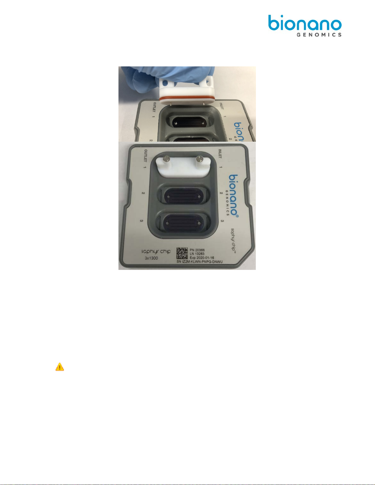
Image: Saphyr Chip (left) and Saphyr Clip (right) with removable plugs (bottom right)

30247 Rev A, Saphyr System User Guide for Saphyr P/N 60325 Page 10 of 43
1. Open the pouch containing the SaphyrChip.
2. Place the chip on a clean and level lab bench.
3. With a 10 µl pipette, press the plunger down and hold at the first stop. Lower the pipettetip into the
sample and gently stir the sample with thetip.
4. Position the pipette tip near the middle or bottom of the sample and slowly aspirate 8.5 µl of thesample.
5. Begin loading the sample in the inlet well of flowcell 1.
Place the pipette tip into theflowcell1inletwellontherightofthechip,andthenslowlydispense the sample
until the bottom of the inlet well is coated with sample solution. Continue to dispense, adjusting the rate of
dispensing as the DNA travels slowly into the flowcell fingers, until the entire volume of 8.5 μl is in the
well.
The fluid level in the inlet well should be flat. If the sample overflows out of the well and onto the top of the
chip or onto the plastic, the flowcell is not usable. Always maintain positive pressure on the plunger to
avoid bubble formation.
6. Repeat steps 3 through 5 for flowcell 2 and flowcell 3 inletwells.
7. Set a timer for 2 minutes to allow the sample to wet through thenanochannels.
8. After two minutes, with a 20 µl pipette positioned near the middle or bottom of the sample, slowly aspirate
11 μl of the sample and slowly dispense the sample into the outlet well of flowcell 1. Repeat for flowcell2
and flowcell 3.
The fluid level in the outlet well should be flat. If the sample overflows out of the well and onto the top of
the chip or onto the plastic, the flowcell is not usable. Always maintain positive pressure on the plunger to
avoid bubble formation.
9. For flowcell 1, add 5 µl of nuclease-free water to the hydration reservoir on the outlet side of the chip (see
“OUTLET” on the chip label. Adding additional water or adding water to the reservoir on the inlet side of
the chip may lead to problems with the chip run.
10. Ensure that the fluid level in the inlet and outlet wells isflat relative to the top of the chip. Add the
necessary volume of nuclease-free water to the inlet and outlet wells of flowcell 1 toreplace sample
solution that hasevaporated.
Important: The inlet and outlet wells should be filled with sample solution during the initial load. Do
not compensate for lack of sample solution by adding nuclease-free water or buffer. Nuclease-free
water should only be added after all wells are loaded to replace volume lost by evaporation.
Outlet Hydration
Reservoir Inlet Hydration
Reservoir
Outlet Well Inlet Well
Fingers
30247 Rev A, Saphyr System User Guide for Saphyr P/N 60325 Page 11 of 43
11. Align the plug (with the electrodes facing down) to flowcell 1. Use a slight to-and-away rocking motion on
the plug to gently insert the plug fully into the chip.
12. Repeat steps 9-11 for flowcells 2 and 3.
Note: It is highly recommended that all flowcells in the chip are used in the same run. Once the chip has
been removed from the original sealed back, the performance will degrade over time.
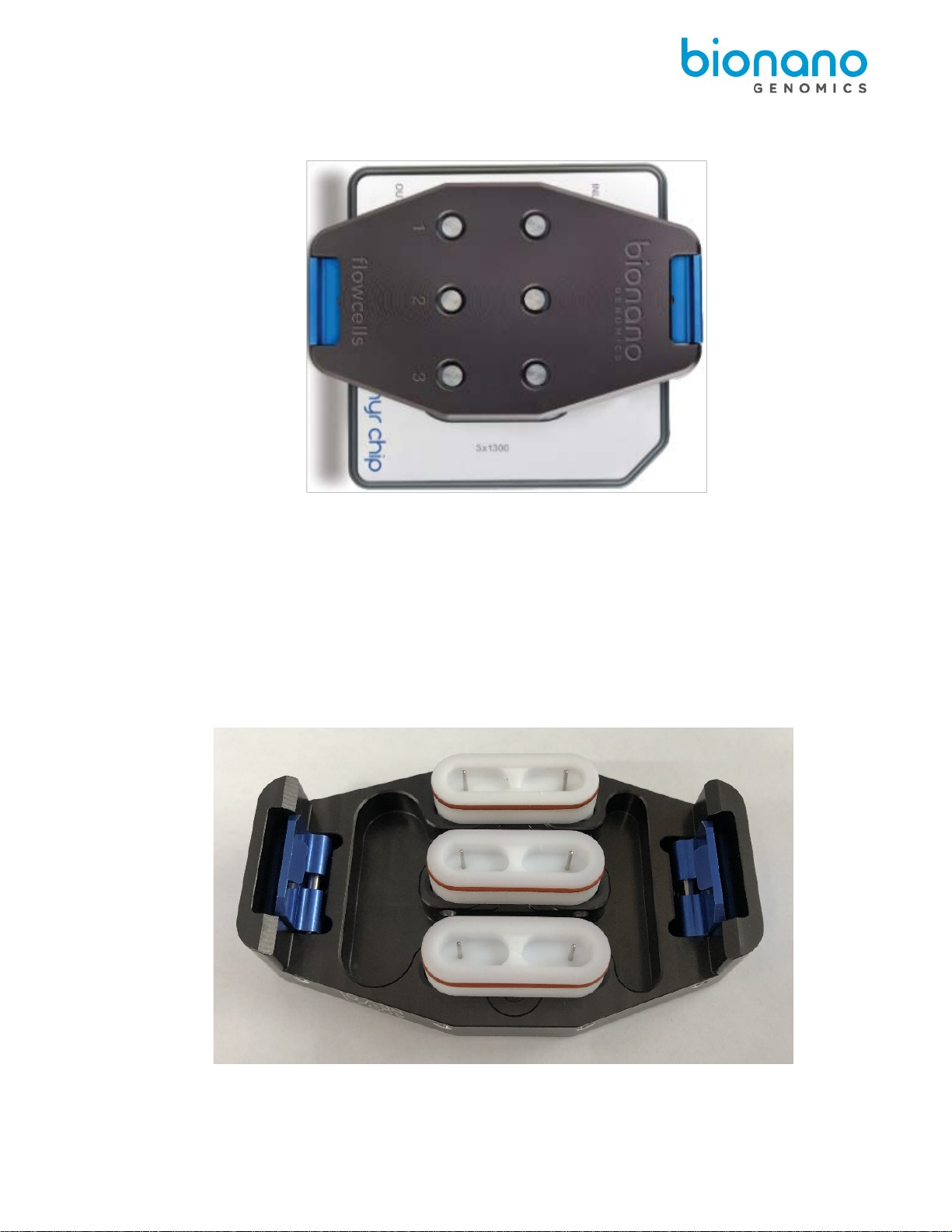
13. Align the Saphyr Clip onto the Saphyr Chip (verify correct orientation) such that the electrode posts on the
Teflon plugs fit in the opening in the clip. Using both hands, simultaneously apply an even downward
force on the right and left hand side of the clip to attach. You will hear a click on each side of the clip
when it is attached. Once the clip is attachedto the chip, do not remove it unless necessary. If you remove
any of the plugs, rehydrate the chip inlets and outlets with nuclease-free water to replace any sample
solution that has evaporated so the fluid level in the wells is flat.
Important: Even if all flowcells do not have samples, all 3 plugs must be inserted into the chip to
ensure proper evaporation control from the clip.
30247 Rev A, Saphyr System User Guide for Saphyr P/N 60325 Page 12 of 43
14. The chip and sample can be left out for up to 1 hour at room temperature with the clip engaged before
starting the run.
Saphyr Clip Care
Always position clip inserts on their side or upside down, as shown below. Do not place them on the bench with
the electrodes down.
Correct Position

30247 Rev A, Saphyr System User Guide for Saphyr P/N 60325 Page 13 of 43
Chapter 5: Perform Run
Insert Saphyr Chip
Before inserting the Saphyr chip into the Saphyr instrument, check the underside of the chip for dust or debris. If
there is dust or debris, gently wipe the underside of the chip with lens paper. Avoid touching the underside of the
chip with anything other than lenspaper.
1. From the Home Screen, click Insert Chip.
Users will hear the stage moving outward, which can take about 10 seconds. When the stage has
reached the proper position to allow for insertion of the chip, the “Chip is Inserted” option will activate on
the screen.
2. Manually lift the sample door of the instrument.
30247 Rev A, Saphyr System User Guide for Saphyr P/N 60325 Page 14 of 43
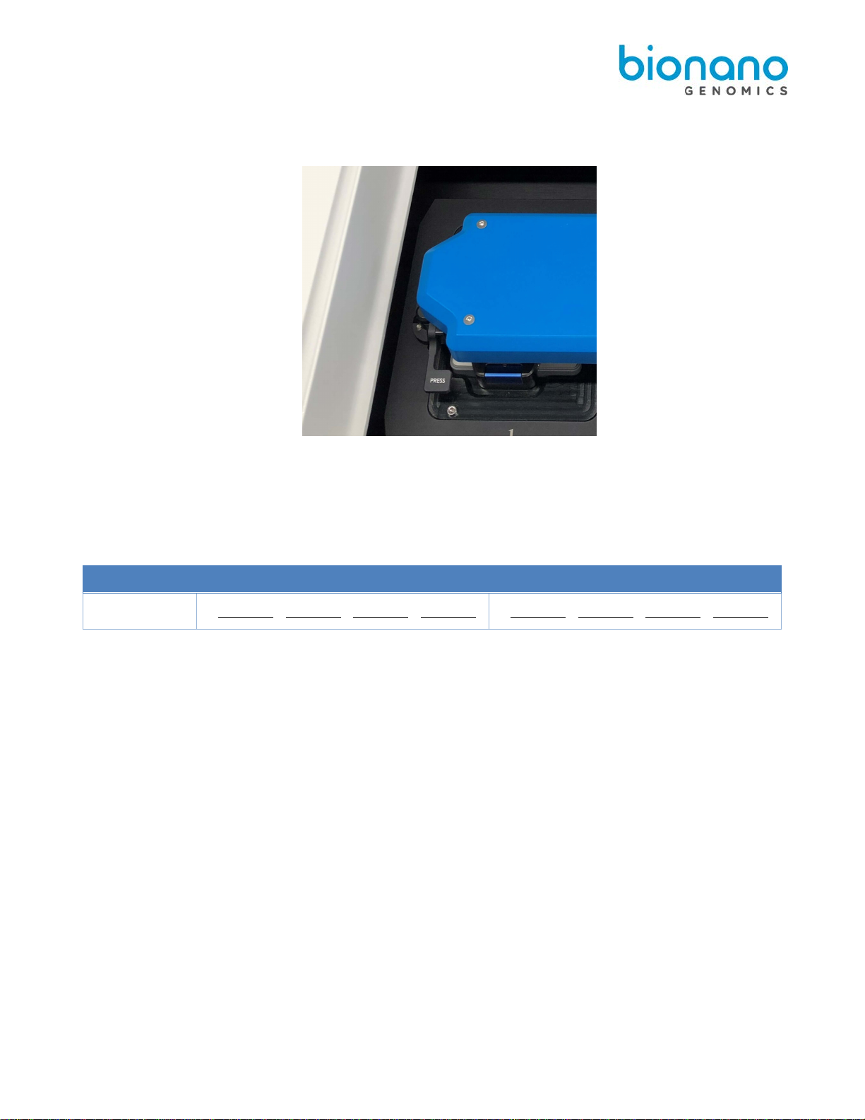
3. Press the button that says “Press” to release the bundle arm.The bundle gently rise to a vertical
orientation, thereby presenting the two positions where the chip(s) can be inserted into the instrument.
4. Insert one or two chips into the instrument and ensure that it rests snugly on the stage. If only inserting
one chip, either platform can be used.
Tip: If loading two chips, record which chip is on which platform. The ICS will ask you which experiment to
associate with each chip (See Configure Run section below).
Stage Position
1 (left)
2 (right)
Chip SN : - - - - - -
5. Gently lower the bundle arm onto the Saphyr clip(s), and then close the sampledoor.
•In the Home Screen, click Chip is Inserted. The instrument will read the barcode to identify the
chip(s). If the instrument is unable to identify the chip barcode, an error message will appear.
Remove the chip and inspect the barcode to see if it is damaged. If not, reseat the chip(s), making
sure that it is centered on the stage mounts. If you have further issues, contact Bionano Support.
6. Proceed to the Configure Run section.

30247 Rev A, Saphyr System User Guide for Saphyr P/N 60325 Page 15 of 43
Configure Run
1. From the Home Screen, click Configure Run. The Configure Run screen appears. If two chips were
inserted, you will be prompted to configure the chip on platform 1 first (Chip Location: P1). Platform 1 is
on the left side of the stage.
2. AttheExperimentfield,selecttheexperimenttoassociatewiththechipfromthedrop-down list.
[Optional] Click Refresh to update the list.
3. If applicable, at the Chip Setup field, select the experiment from the drop-down list.
Note: This step is only applicable if there is more than one chip associated with the experiment. This will
take you to the expanded Configure Run screen (below).
4. Review the runtime and throughput target parameters for each of the flowcells. These values will default
to the values that were entered into Bionano Access during the experiment setup (this feature requires
Bionano Access v1.4 or higher). The user may decrease the runtime or throughput as desired.
Note: If the chip has been run previously, the runtime limit and throughput target may be modified. See
Appendix B for details.

30247 Rev A, Saphyr System User Guide for Saphyr P/N 60325 Page 16 of 43
5. [Optional] Prior to clicking Accept or Next, you can click on either Skip Current Chip or Remove Chips.
a) Skip Current Chip – This will allow you to disregard the chip in this platform. The chip will not be run.
See the Chip and Flowcell States section below for more details.
b) Remove Chips – This will allow you to stop configuring runs and remove the chip(s), if needed. After
chips are removed, you will return to the Home Screen.
6. [Optional] Clicking on the arrow next to Advanced… will give you the option to save the images that are
captured during the run. By default, images are not saved. If you choose to save images, see Appendix E
on managing that data.
7. If you have inserted two chips into the instrument, click Next and repeat steps 2-6.
Note: If the second chip belongs to a different user, change users before starting the second chip
configuration.
8. Click Accept.
9. If you have inserted two chips, you will have the option of which chip to run first. Click Start Run on the
chip you want to run first.
10. Saphyr starts the following process:
a) Chip Registration (Approximately 5 minutes)
b) DNA Loading Optimization (Approximately 1 hour)
c) Scanning
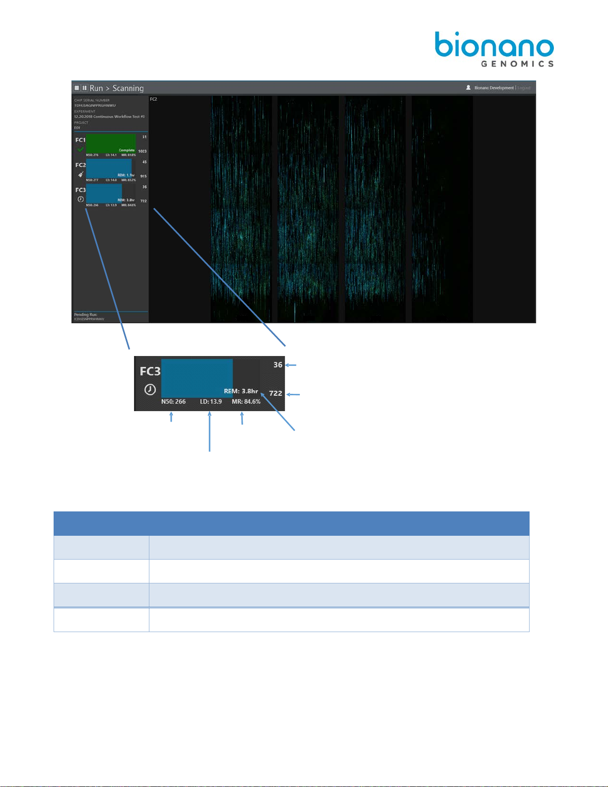
11. During scanning, the user can view the run metrics and most recent images on the Run Dashboard. Run
metrics are also available to view in Bionano Access.
30247 Rev A, Saphyr System User Guide for Saphyr P/N 60325 Page 17 of 43
Note: The color of the progress bar indicates the following:
Color Description
Blue Flowcell is running
Green Flowcell has completed running
Yellow Flowcell has been cancelled and is stopping
Red Flowcell has stopped due to an error
Gbp from the previous scan
TotalGbp collected during this run
Estimated time remaining –Either
to hit throughput target or when
the maximum time is reached
Map Rate
Label Density
(labels per 100 kbp)
N50 (kbp) for
molecules ≥
150 kbp

30247 Rev A, Saphyr System User Guide for Saphyr P/N 60325 Page 18 of 43
12. Clicking on one of the flowcells expands the details of the run metrics for that flowcell. In the expanded
view, you can see the per-scan throughput and map rate metrics:
When the chip run is complete, if there is another chip (“pending”) in the instrument, it will automatically start
running. The pending chip will be shown on the bottom left of the screen.
Once all chips on the instrument have been completed ICS will return to Home Screen. Check the Run Info
Icon for run details.
Chip and Flowcell States
Depending on the situation, the chip(s) and their respective flowcells may be in various different states.
Chip State Description
Running A chip in the instrument is current running (data is being collected on one
or more flowcells)
Complete A chip has finished its run. This means that all of the associated flowcells
have either reached their throughput or time limit, an issue has occurred
(see flowcell states), or the user has stopped the run.
Pending A chip is ready to run (loaded into the instrument, and the user has
configured a run), but is awaiting the completion of a currently running
chip.
Unscheduled A chip is loaded into the instrument, but the user has not configured a
run.

30247 Rev A, Saphyr System User Guide for Saphyr P/N 60325 Page 19 of 43
When a chip is running, the flowcells associated with the chip can be in any of the following states:
Flowcell State
Description
Icon
Loading Sample is being loaded in preparation for scanning.
Scanning The flowcell is being imaged.
Cleaning Post-scanning cleaning is taking place.
Complete Flowcell has achieved its throughput target or runtime limit as
defined in the Run Configuration.
Evaporated The instrument is unable to load DNA in the flowcell due to loss of
contact. See the Pausing a Run to Rehydrate the Chip section
below for more information.
Error An error has occurred that has prevented the instrument from
collecting data.
Cancelled The flowcell was cancelled by the user and will stop when
possible.
Paused The flowcell is temporarily paused by user request.
Waiting The flowcell is waiting for instrument resources to become
available to load or scan.
Note: When all flowcells cease to be in a Loading, Scanning, Cleaning, or Waiting state, the chip state then
changes from “Running” to “Complete”.
Pausing a Run to Insert a New Chip and/or Remove a Completed Chip
In order to support continuous data collection, a run may be paused in order to swap out a chip that has already
completed with a new one.
1. Press the pause icon at the top left of the user interface.

30247 Rev A, Saphyr System User Guide for Saphyr P/N 60325 Page 20 of 43
2. When you are asked whether you want to pause the run, click yes. The current scan will complete before
the run is paused. This may take up to 15 minutes.
3. You will be prompted to insert and remove chips. Open the sample door to add and/or remove chips as
described in steps 2-6 of the Insert Saphyr Chip section above. Be sure not to remove the chip that you
are currently running if you want it to continue running. Press Resume when you have the new chip
inserted.
a. If the Active Chip is Removed (from the instrument or moved to another platform) ICS will detect the
move and will prompt a warning indicating that the current run will be stopped if the user continues.
Table of contents
Other BioNano Genomics Laboratory Equipment manuals


Popular Laboratory Equipment manuals by other brands

Amos
Amos TEC 2800 Operation manual

Ti-Research
Ti-Research Cast Product information

Agilent Technologies
Agilent Technologies 6500 Series Maintenance Guide

Accuris
Accuris SmartDrop L NS1000 Operation manual

Thermo IEC
Thermo IEC FRENCH Press FA-078A Operation manual

Hamilton
Hamilton DIGITAL MEDIA LAB quick start guide

Agilent Technologies
Agilent Technologies M9302A Startup guide

Cole Parmer
Cole Parmer RHC-400 User's operation manual

IKA
IKA ULTRA-TURRAZ UTL 1000/10 operating instructions

CORNING
CORNING LSE 6703 instruction manual

Kilowatt Labs
Kilowatt Labs SIRIUS 500-12-B-1C SL Series user manual

Sihon
Sihon SH0004P installation instructions


