Interceptor
Interceptor
Page 3 of 6
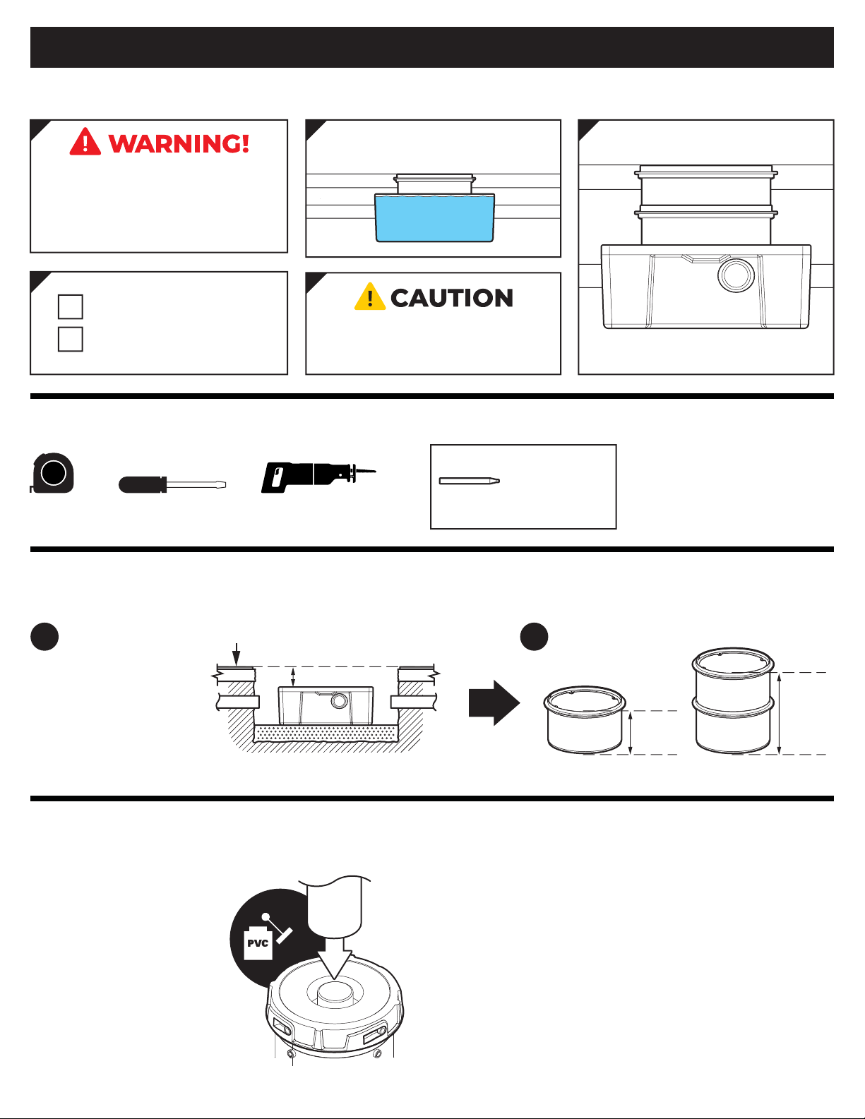
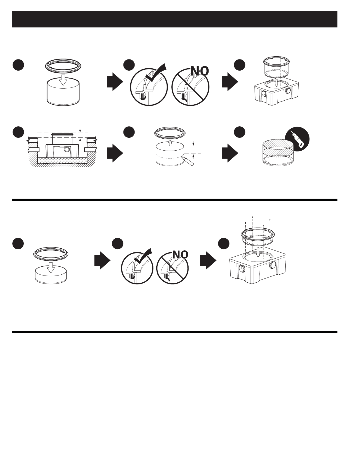
FCR1 Installation Guide
SPECIAL PRECAUTIONS
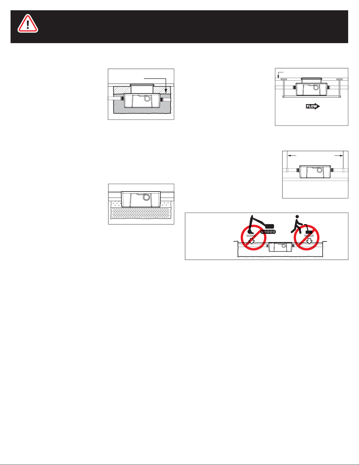
Install unit on solid, level surface in
contact with the entire footprint of
unit base; for suspended
installations design trapeze to
support the wet weight of the unit.
Do not partially support unit or
suspend unit using metal
U-channel to create a trapeze.
Fully Support Base of Unit
For above grade installations ensure
heavy inlet and outlet piping (such as
cast iron or long runs) is properly
supported or suspended during the
entire installation process to prevent
connection failure or damage to
bulkhead fittings.
Support Inlet and Outlet Piping
DO NOT
COMPACT
BACKFILL
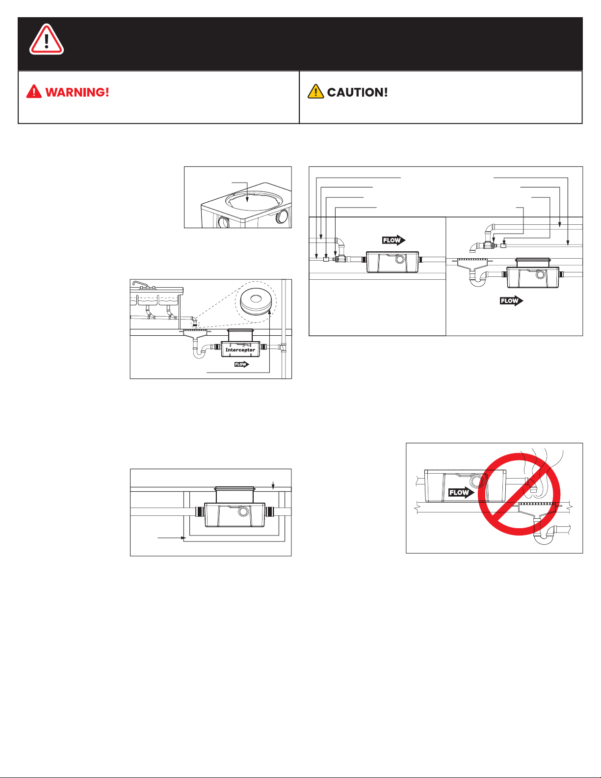
For Schier Grease Interceptor Installations - Failure to follow this guidance
voids your warranty
High Water Table Installations
Interceptors and risers are not designed
to withstand water table height in
excess of the top of the unit when buried
(see figure). If it is possible for this to
occur, install the interceptor and risers in
a water-tight concrete vault or backfill
with concrete or flowable fill (wet
concrete and flowable backfill should be
poured in stages to avoid crushing the
interceptor). At risk areas include but are not limited to tidal surge areas,
floodplains and areas that receive storm water. Great Basin™ models
that are direct buried in high water table scenarios must be installed
with an anchor kit. Models GB-50, GB-75, and GB-250 use model AK1
anchor kit. Model GB-500 uses model AK2 anchor kit for use with
deadmen anchors. Models GB-1000, GGI-750 and GGI-1500 use model
AK3 anchor kit for use with deadmen anchors.
max water table height
for direct burial
pipe supports
Interceptor
Interceptor
Interceptor
Interceptor
concrete floor
suspended installation
Flush-to-Grade Burials
Flush-to-Grade buried installations
(without a riser) are not recommended
for heavy foot traffic areas without the
use of an internal gusset support kit
SGK2 (for GB2) or SGK3 (for GB3).
Interceptor
Interceptor