automatic cable rewinder FT 260/350 - EFT 265 e-mobility with integrated charging electronic
installation and operating instruction
installation and operating instruction FT 260_350-EFT 265 e-mobility miL - A5 - Version A Seite 3/12 25.09.2020
Schill GmbH & Co. KG; Bruckstraße 44; 70734 Fellbach www.schill.de
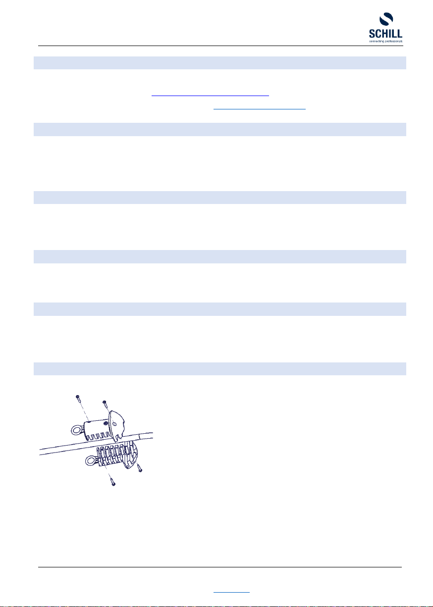
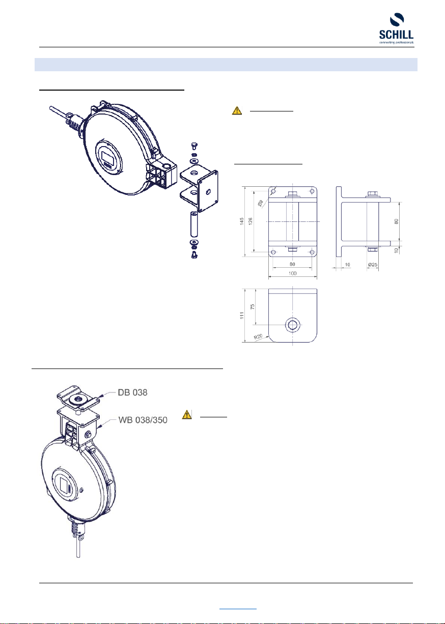
LOCKING DEVICE
As a standard feature the
cable reel has a disengageable cable
locking device. The latching mechanism ensures that the pulled-
out cable stays without traction fixed
in place. When the cable is
being pulled out, the spring
detent passes over a series of grooves.
An audible click indicates that the
locking device is engaged. If you
gently rewind the cable after
the clicking sound, you will notice that
the spring detent will
engage into the notches, locking the cable in
position. The cable can be disengaged by gently continuing to pull
the
cable until the click can no longer be heard. The tensioned
spring will pull the cable back onto the reel.
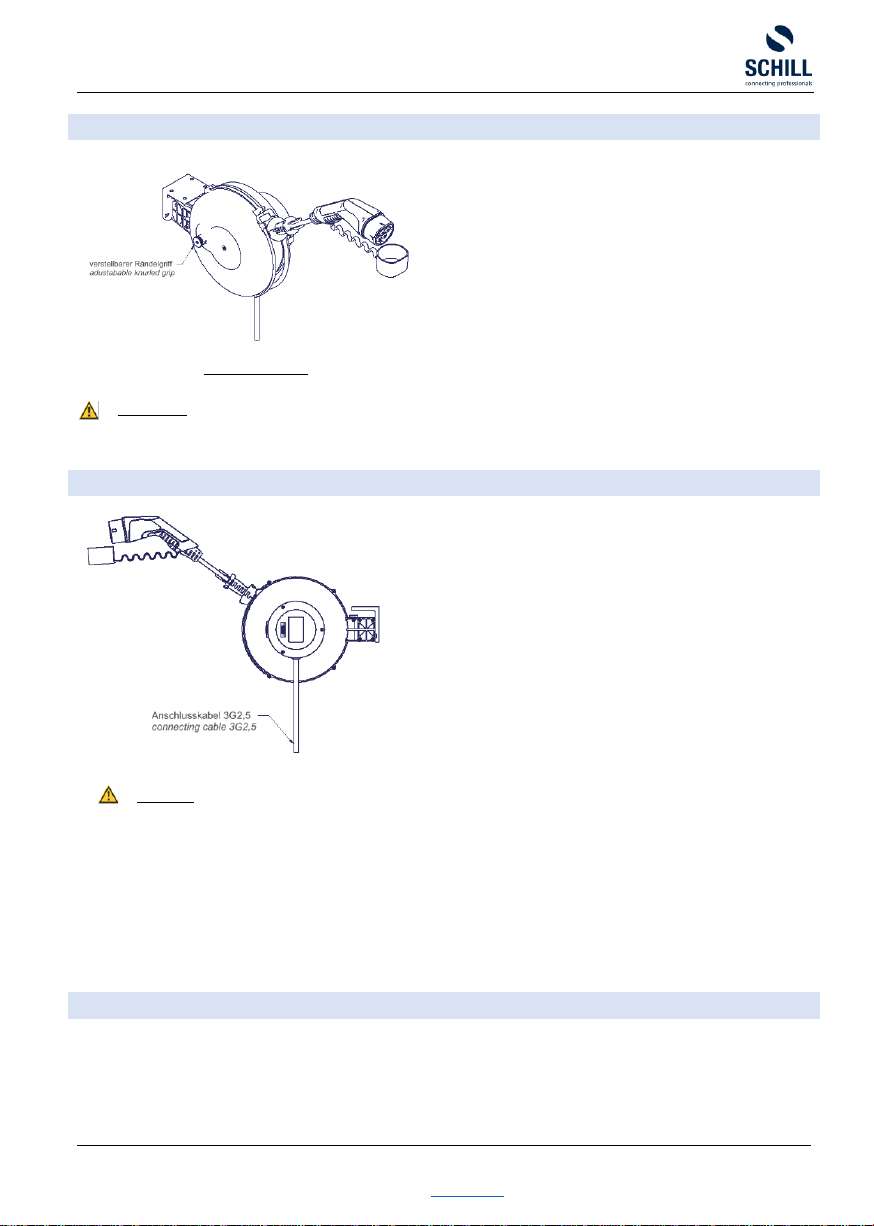
Only the locking device FT 260 and FT 350 can be disengaged by pulling the knurled grip out by approx. 1cm and turning it between
90° and 180°. This will disengage the locking device the cable is then constantly under tension.
ATTENTION
Do not release the cable when rewinding, the tension of the spring can accelerate the winding speed to such a degree that the
swinging cable end could cause injury. Also damage to the cable and spring could be the result of such an action.
CONNECTING
To connect the reel to the mains/supply service a 2m connection cable
H07RN-F 3G2,5 / H07 RN-F 5G2,5 is mounted. As a standard a plug-in
connector is not included in the scope of supply.
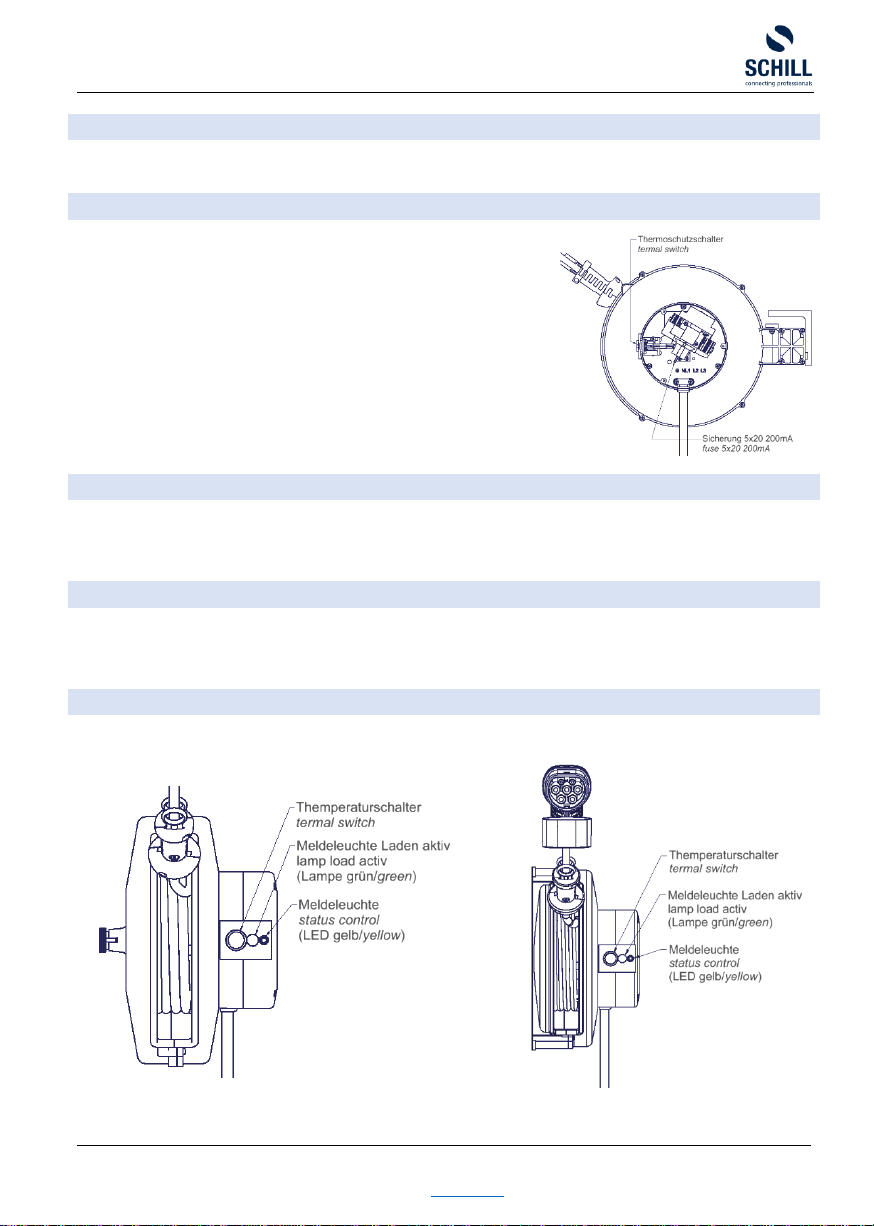
The connection cable can be shortened and connected in individual
lengths.
ATTENTION
•Observe installation instructions
•According to DIN VDE 0100-722 (VDE 0100-722): 2013-01, a separate circuit must be set up for each charging socket
(IEC 60364-7-722: Low-voltage electrical installations - Part 7-722: Requirements for special installations or locations -
supply of electric vehicle)
•Protection via residual current device (RCD) at least type A, which switches off with AC or pulsating residual current
with IΔn ≥ 30mA
•If DC fault currents IΔn ≥ DC 6mA can occur due to insulation faults in the charging circuit, a residual current device
(RCD) type B is required or suitable protective measures for DC fault currents ≥ DC 6mA must be provided (e.g. DC
residual current monitoring device).
EXTENSION CABLE
The included standard cables are designed to tolerate the weight of the pulled-out cable including the cable stopper. Additional weights
are not allowed. The mounted cables are limited to the specified lengths. Never use excessive force to unwind the cable as this can
damage both the cable and the reel. Should the cable be blocked while coiling up, please pull the cable out again and recoil. Attention
should also be paid to section „GENERAL".
If the cable is damaged, please contact us (see "CONTACT").