automatic cable rewinder FT 260 / EFT265 LAN
installation and operating instruction
installation and operating instruction FT 260_EFT 265 LAN - A5 page 4 09.04.2021
Schill GmbH & Co. KG; Bruckstraße 44; 70734 Fellbach www.schill.de
READY FOR USE
Before commissioning, check whether the free end of the pull-out cable (RJ45) is correctly connected to a terminal. After connecting the
patch cable to the RJ45 socket and establish the network connection, a test to prove the network functionality should be conducted.
TECHNICAL DATA
Our cable reels with their robust design are made for operating in factories and workshops. The sturdy plastic design, made from high-
quality materials, is completely electrically insulated, corrosion resistant and has very good winding characteristics. The cable reels come
as a standard without connection cable.
•Spiral spring for approx. 30.000 operations
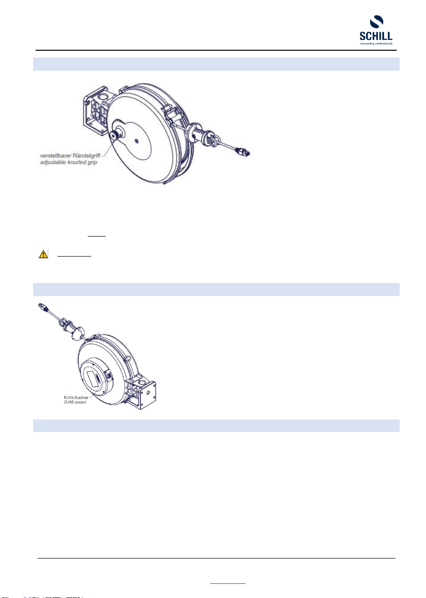
•Cable locking device (disengageable only FT versions) with spring detent
•Data slip ring:
➢Voltage: 240VDC / 240VAC
➢Dielectric strength 500VAC @60Hz @ 60sec
➢Current 1A continuous - 2A peak
➢Insulation resistance >500MΩ / 500VDC
➢Contact Gold –Gold (alloy)
➢Dynamic contact resistance ≤ 10mΩ
•Data transfer: 1 Gbits / s Ethernet
•Application : 100BASE-TX / 1000BASE-T
•Extension cable: 10m S/FTP CAT6 4x2 AWG 26
•Cable stopper with segmented gentle clamp 6 –12 mm
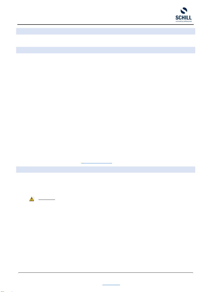
•Connection terminal: RJ45 socket at the connection cover
•Traction: Za= 9N / Ze= 30N
•Weight: 2,2 kg
•Universal holder for wall or ceiling installation
•Ambient temperature range -20°C bis 40°C
•IP classification IP 20
•Protection class II
The stated operating temperatures relates only to the standard cable reel as described below. Specification for plug in devices can be
found within the relevant standard DIN EN 60390.
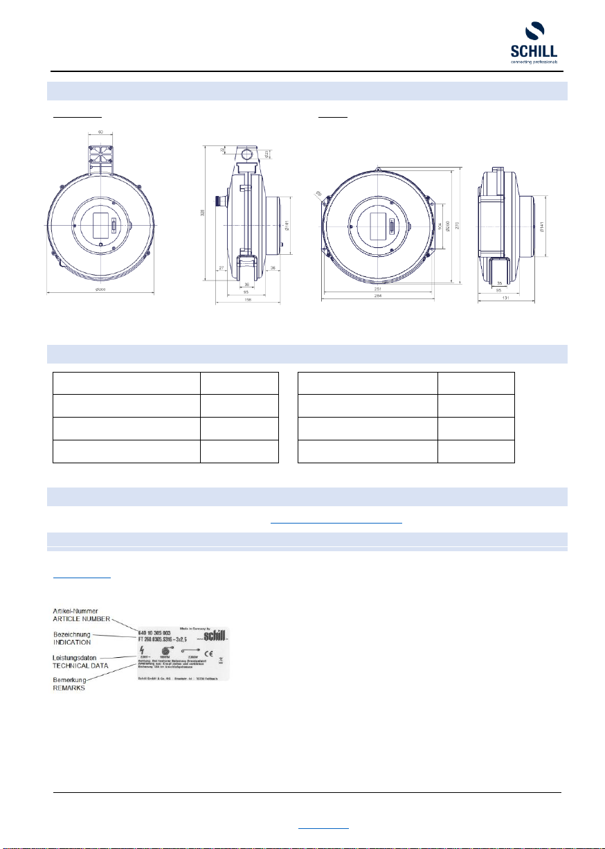
Additional information with respect to cable types, spring tensions, power loads and weights can be found on the product rating plate, in
our current product catalogue and on our website https://www.schill.de/en/
EXCHANGING THE PULL-OUT CABLE
•Disconnect the cable reel and remove from the operation site.
•Remove the cover with the RJ45 socket.
•Remove the RJ45 socket from the cover.
•Loosen all the screws from slip ring and housing cover.
•Carefully remove the housing cover, guiding the slip ring through the large hole in the housing.
ATTENTION
The spiral spring in the coil is under tension. Please ensure that the locking mechanism is activated.
•To replace the pull-out cable, you should make sure the spring is unwound for your own safety! Please adhere to the following
instruction:
1. Place the slip ring in the coil and fix it.
2. Carefully pull on the cable stopper until the click of the notches have faded, you immediately notice a pull on the cable
stopper in the opposite direction.
3. Let the coil run back slowly and count the number of turns. This is important to adjust later the exact preload on the
spring again, without damage to coil or spiral spring. In the end the coil should be able to move freely.
4. Remove completely the damaged cable from the coil and disconnect the RJ45 socket.
5. Remove strain relief inside the coil.
6. Remove defective pull-out cable.
7. Remove the cable stopper and where appropriate the heat shrink tubing from the defective cable and attach to the new
cable.
•Undertake the re-assembly in reverse order (see “TIGHTENING TORQUE”).
•Adjust the pre-load:
Hold the stopper outside the housing and hold it with one hand. Now turn the coil as often as you counted. At the end let it snap
into the notches (see "LOCKING DEVICE").