Schiller Classen TA18AHD Instruction Manual

MAN 4177728
Rev. C08-2022
PARTS, OPERATOR’S & SAFETY MANUAL
COMPACT AERATOR
TA18AHD
TA18AKHD

WARNING
The engine exhaust from this product
contains chemicals known to the State of
California to cause cancer, birth defects
or other reproductive harm.
CALIFORNIA PROPOSITION 65
WARNING: Cancer and Reproductive Harm - www.P65Warnings.ca.gov.
ADVERTENCIA: Cáncer y Dãno Reproductivo - www.65Warnings.ca.gov.
El estado de California hace saber que los
gases de escape de este producto con-
tienen productos quÍ mi-cos que producen
cá ncer, defectos de nacimiento y otros
dañ os en el proceso de reproducció n
humana.
ADVERTENCIA
PRE-DELIVERY CHECK LIST
Check the following before you deliver the Aerator to the
customer.
1.
. Guards and shields fastened in plac
2.. Decals fastened and legibl
3.
. eight bar installed.
4.
. Gas lever on engine turned o
5. All lubrication points greased.
6.
. 6:1 gearbox oil leve
7.. Engine oil leve
8.. Ai cleaner.
9. Touch up scratches.
10.
0. Chain(s) tig
11.
. Lowering handle working proper .
12.
2. Control handle(s) working to tighte -belt(s).
13. Add fuel, start engine, test run.
DATE SET UP __________/__________/__________
DELIVERY CHECK LIST
Review the operators manual with the customer.
1.
. Schiller Grounds Care, Inc. warran .
2.
. Safe operation and servic
3.. How to use control
4.
. Operating the machine correct .
5. Transporting the Aerator.
6.
. Correct fuel and lubricant
7.. Daily and periodic inspection
8.. Changing oil after break-in perio
9.. Servicing th Aerator regularly and correctly.
10.10.Schiller Grounds Care, Inc. parts and servi
11.
. Give the customer the operators manual a
encourage customer to read it.
DATE DELIVERED __________/__________/________
SIGNATURE __________________________________
OWNER’S RECORD
DATE PURCHASED ___________
AERATOR MODEL NUMBERNUMBER _________________
AERATOR SERIAL NUMBERNUMBER _________________
ENGINE MODEL NUMBERNUMBER
ENGINE SERIAL NUMBERNUMBER
_________________
________________

IMPORTANT MESSAGE
This Operation / Part Manual provides the information necessary for safe and efficient operation and service.
For your safety, it is important that you read and understand this entire manual before operating your
equipment.
This Operator's Manual is part of the machine. Suppliers of both new and second-hand machines must make
sure that this manual is provided with the machine. Learn the proper operation of all controls. Observe all
safety precautions. Follow all instructions and warnings completely. Do not remove or defeat any safety
features.
Schiller Grounds Care, Inc.
1028 Street Road
Southampton, PA 18966
PHONE 877-596-6337 • FAX 215-357-8045
TABLE OF CONTENTS FIGURES PAGE
SAFETY.........................................................................................................................................................4-7
LABELS............................................................................................................................................................8
CONTROLS......................................................................................................................................................9
OPERATION..............................................................................................................................................10-11
MAINTENANCE / STORAGE....................................................................................................................12-13
PARTS............................................................................................................................................................15
MAIN ASSEMBLY......................................................................................................................................16-17
HANDLE AND CONTROL ASSEMBLY .....................................................................................................18-19
TINE ASSEMBLY ......................................................................................................................................20-21
WARRANTY ............................................................................................................................... BACK COVER
DETAILS
MEASUREMENTS
U.S. Units of measure are used in this manual.
SERIAL NUMBERS
Write frame and engine serial numbers, plus model
num-bers in “Owner’s Record” section below. You may
need these numbers when you order parts.
ORDERING PARTS
When ordering parts, always give the serial number and
model of your Aerator as well as the quantity, part number
and description of the part needed.
DIRECTIONS
“Right Hand” and “Left Hand” sides of the Aerator are de-
termined by facing the “back” of the Aerator as you would
operate the machine.
3
AERATOR

4
AERATOR
NOTICE !!!
Unauthorized modifications create extreme safety
hazards for operators and bystanders along with
potential product damage.
Schiller Grounds Care, Inc. strongly warns
against, rejects and disclaims any modifications,
accessories or product alterations that are not
designed, developed, tested and approved by the
Schiller Grounds Care, Inc. Engineering
Department. Any Schiller Grounds Care, Inc.
warranty is voided if a product is altered, modified
or changed in any manner without approval from
Schiller Grounds Care, Inc.
Any and all liability for personal injury and/or
property damage caused by unauthorized
modifications, accessories or product alterations
are considered the responsibility of the
individual(s) or company designing and/or making
such changes. Schiller Grounds Care, Inc. will
vigorously pursue full indemnification and costs
from any party responsible for such unauthorized
post-manufacture modifications and/or
accessories should personal injury and/or
property damage result.
This symbol means:
ATTENTION!
BECOME ALERT!
Your safety and the safety of others is involved.
Signal word denitions:
The signal words below are used to identify levels
of hazard seriousness. These words appear in this
manual and on the safety labels attached to Classen
machines. For your safety and the safety of others,
read and follow the information given with these
signal words and/or the symbol shown above.
DANGER indicates an imminently hazardous
situation which, if not avoided, WILL result in death
or serious injury.
WARNING indicates a potentially hazardous
situation which, if not avoided, COULD result in
death or serious injury.
CAUTION indicates a potentiallyhazardous situation
which,ifnotavoided,MAY result in minor ormoderate
injury. It may also be used to alert against unsafe
practices or property damage.
CAUTION used without the safety alert symbol
indicates a potentially hazardous situation which, if
not avoided, MAY result in property damage
MODEL NUMBER: This number appears on
sales literature, technical manuals and price lists.
SERIAL NUMBER: This number appears only
on your machine. Use this number when
ordering parts or seeking warranty information.
SAFETY

•Read the operation manual.
•Read the engine manufacturer's owner manual.
•Explain this material to any operator or mechanic
who cannot read English.
•Contact your factory representative for
clarification if any portion of this material is
unclear.
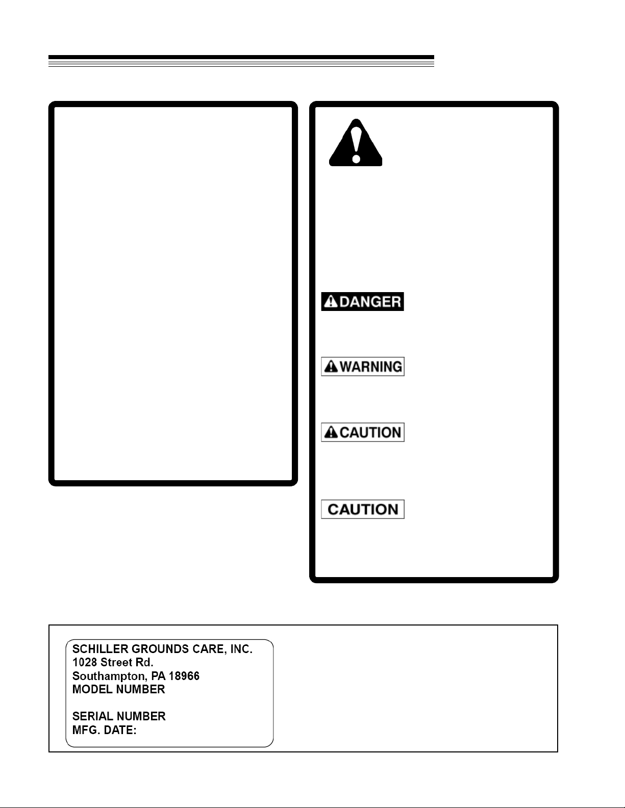
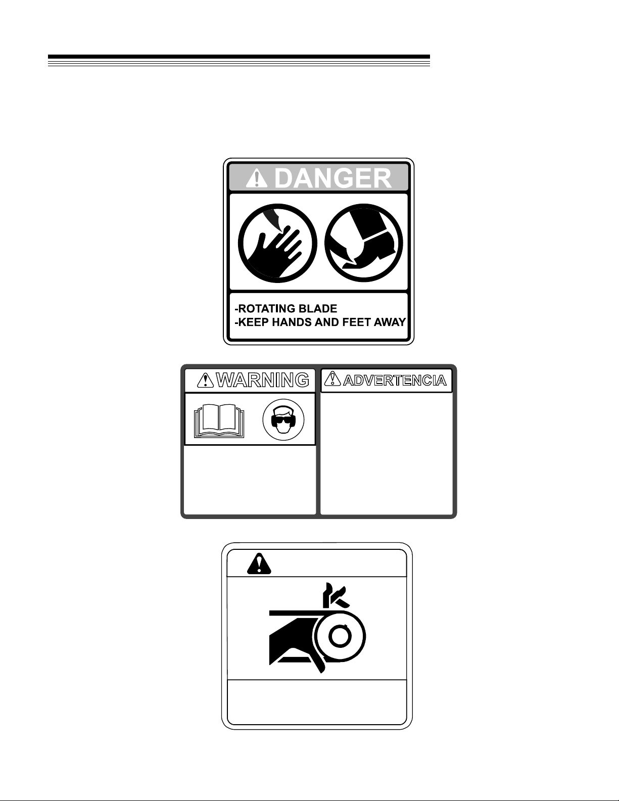
•Adhere to the warnings and instructions depicted
in the safety decals on the machines.
•Replace any missing or damaged labels.
•Keep warning labels and this operator's manual
legible and intact.
•Become familiar with the safe operation of the
equipment, operator controls and safety signs.
•Know how to stop the engine and attachments
quickly in an emergency.
•Do not operate or allow another person to
operate this machine if there are any questions
about safety.
•Train all operators and mechanics; the owner is
responsible for training the users and for
accidents or injuries occurring to themselves,
other people or property.
•Never attempt to use a machine that is damaged
or has unauthorized modifications.
•Wear appropriate clothing, including long trousers
and gloves.
•Do not operate barefoot or wearing open sandals.
•Do not operate with loose clothing, long hair or
jewelry which may get tangled in moving parts.
•Wear hearing protection.
•Wear safety glasses with side shields.
•Wear a dust mask to avoid breathing dust.
•Never allow underage children (as defined by
local regulations), unskilled or improperly trained
people to operate this equipment.
•Do not operate machine while under the influence
of drugs, alcohol, or any other condition of
impairment.
•The owner/user can prevent and is responsible
for accidents or injuries occurring to themselves,
other people or property.
Site preparation and circumstances
•Evaluate the terrain to determine what
accessories and attachments are needed to
properly and safely perform the job.
•Only use accessories and attachments
approved by the manufacturer.
•Identify and mark buried objects such as sprinkler
heads, stakes, water valves, sewer pipes, water
pipes, electric wires, etc.
•Remove all objects or debris from the area that
may be picked up or thrown by the machine.
•Keep pets and people, especially young
children, away from the area and immediately
cease operation of the equipment if any enter
the area.
•Operate only in daylight or in good artificial light.
•Evaluate the terrain to determine how to safely
perform the job.
Machine Preparation
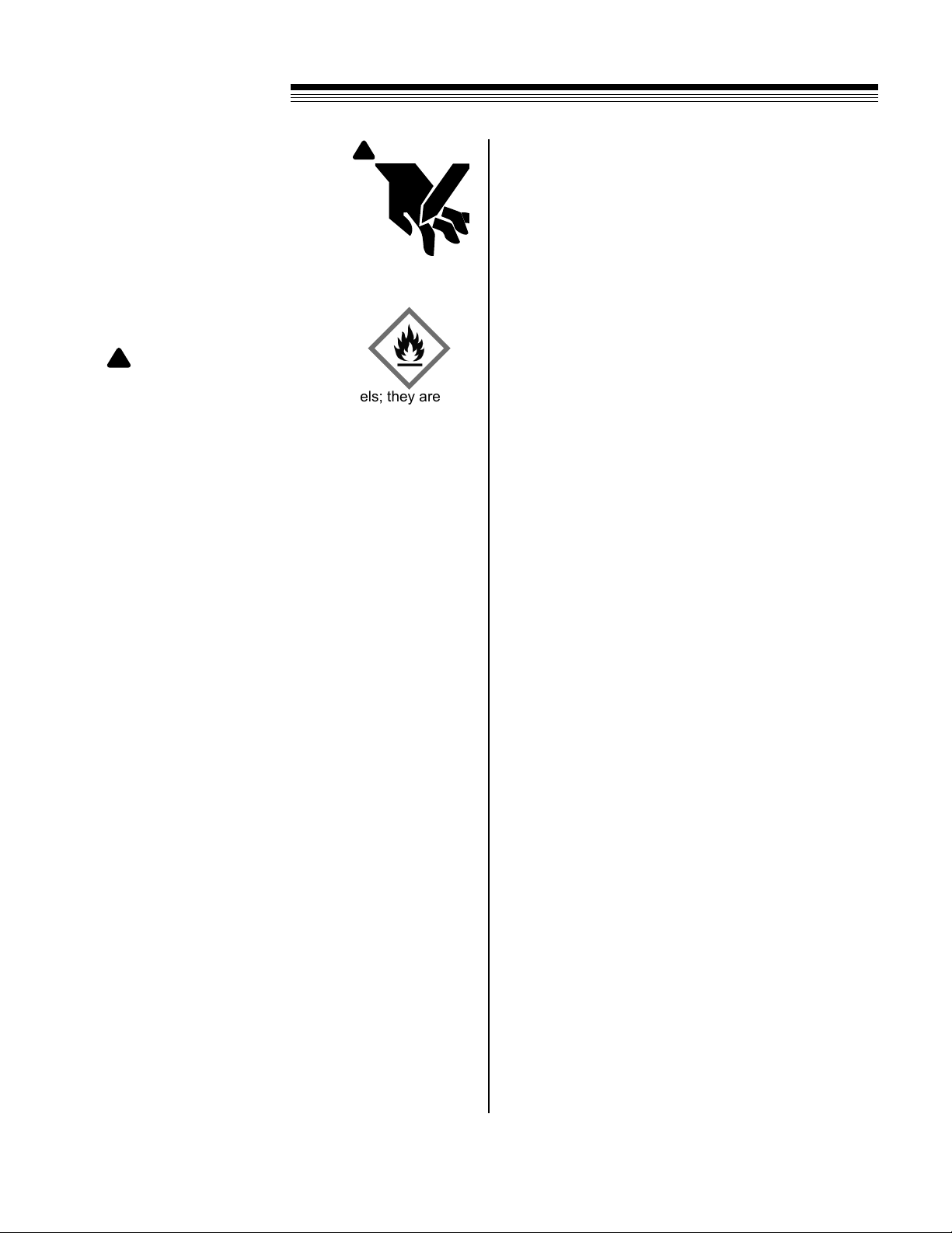
•Do not tamper with or defeat safety devices; they
exist for your protection.
•Keep guards, shields and interlocked safety
devices in place and in proper working condition.
•Keep all fasteners—nuts, bolts and pins—
secured.
•Visually inspect tines for wear or damage and
replace worn or damaged parts.
•Verify that machine and attachments, if any, are in
good operating condition.
•Do not engage tines until ready to aerate.
SAFETY
5
AERATOR
Operator Preparation and Training

Operating On Slopes
Use Extra Care When Working On Slopes
•All slopes require extra caution.
•Evaluate the risks involved before operating on slopes
•Do not operate on slopes if uneasy or uncertain.
Ultimate responsibility for safe operation on slopes
rests with the operator.
•Do not operate on steep slopes.
•Keep all movement on slopes slow and gradual.
•Do not aerate near drop-offs, ditches or embankments.
Uneven terrain can overturn a machine or cause it to
slide.
•Do not turn on slopes unless necessary, and then turn
slowly and downhill when possible.
•Be sure of your footing on slopes.
Interrupting Operation
•Before leaving the operator’s position for refueling,
project end, or transport:
-Park on level ground
-Release control handle
•- Lift up on the tine lowering handle
-Shut off the engine
- Wait until tines stop moving
•Before inspection, maintenance, or repair:
- Park on level ground
- Release control handle
- Shut off the engine
- Wait until tines stop moving
- Disconnect spark plug wires
•When not aerating or crossing surfaces other than
grass:
-Release control handle
- Lift up on the tine lowering handle
•Reduce the throttle setting during engine shut-down
and, if the engine is provided with a shut-off valve, turn
the fuel off at the conclusion of operation.
MAINTENANCE SAFETY
GENERAL
•Maintain machine according to manufacturer’s
schedule and instructions for maximum safety
and best results.
•Park machine on level ground.
•Never allow untrained personnel to service
machine.
•Guards should only be removed by qualified
mainte-nance technician for maintenance/service.
Replace when work is complete.
•Adjust or repair only after the engine has been
stopped and the tines have stopped moving.
•Disconnect spark plug wire(s) before doing any
maintenance.
•Replace parts if worn, damaged or faulty. For
best results, always replace with parts
recommended by the manufacturer.
•Do not dismantle the machine without releasing or
restraining forces which may cause parts to move
suddenly.
•Provide adequate support for lifted machine or
parts if working beneath.
•Do not put hands or feet near or under rotating
parts.
•Clean up spilled oil or fuel thoroughly.
•Replace faulty mufflers.
•To reduce fire hazards, keep the engine, muffler,
and fuel storage area free of grass, leaves, debris
buildup or grease.
SAFETY
6
AERATOR
OPERATION SAFETY
GENERAL
•Use extra care when loading or unloading the ma-
chine into a trailer or truck. Never pick up or carry
the machine when the engine is running.
•Use caution when making turns and crossing roads
and sidewalks. Stop tines when not aerating.
•Do not run the engine in an enclosed area where
dangerous carbon monoxide fumes can collect.
•Never leave a machine unattended. Always turn off
tines and stop engine when leaving the operator
position.
•Use extreme caution when reversing or pulling ma-
chine towards you.
•Remove debris from mufflers and engine to help
prevent fires.
Some repairs or adjustments require the engine to be
running. Keep hands and feet clear of moving parts in
these circumstances.

!
WARNING
Tines
The aerator tines are sharp and can
cut. Use extra caution when handling.
Remove obstructions with care. Wrap
the tines or wear gloves.
•Only replace tines. Never straighten or weld.
•Keep other persons away from tines.
Fuel
•Use extra care when handling fuels; they are
flammable. Gasoline vapors are explosive.
•Store only in containers specifically designed
for fuel.
•When refueling or checking fuel level:
-Stop the engine and allow to cool
-Do not smoke
-Refuel outdoors only
-Use a funnel
-Do not overfill
-Clean up all spills and wait for vapors to
clear before starting the engine
To prevent static electricity sparks:
•Keep containers electrically grounded;
flowing fuel can generate static electricity.
•Refill fuel containers on the ground away
from the vehicle; do not fill containers in a
vehicle or on a truck or trailer bed with a
plastic liner.
•When practical, remove equipment from the
truck or trailer and refuel it on the ground.
•If equipment must be refueled on the truck or
trailer, refuel from a portable container rather
than a dispenser nozzle.
•Keep the dispenser nozzle in contact with the
rim of the fuel tank or container opening until
fueling is complete.
•Do not use a nozzle lock-open device.
•Replace caps on fuel cans and tanks securely.
•Change clothing immediately if fuel is spilled on
it.
!
WARNING
SAFETY
Storage Safety
• Stop the engine and allow to cool before storing.
• Drain the fuel tank outdoors only.
• Store fuel in an approved container in a cool, dry
place.
• Keep the machine and fuel containers in a locked
storage place to prevent tampering and to keep
children from playing with them.
• Do not store the machine or fuel container near
heating appliances with an open ame, such as a
water heater, or an appliance with a pilot light.
• Keep gasoline storage area free of grass, leaves
and excessive grease to reduce re hazard.
• Clean grass and debris from cutting units, drives,
mufers and engine to help prevent res.
7
AERATOR

SAFETY LABELS
-Read and understand Operator
manual and labels.
-Wear hearing and eye protection.
-Replace labels and Operator
manual if lost or damaged.
BEFORE STARTING:
WARNING
-Lea y entienda el manual del
operador y las etiquetas.
-Pide que alguien lea y explique el
manual y las etiquetas a usted si
usted no lee Inglés.
-Use protección ocular y auditiva.
-No haga funcionar sin los
protectores en su lugar.
-Pare el motor antes de dar servicio
-La gente a más durante la
operación.
4165977
ADVERTENCIA
Antes de comenzar:
- ROTATING PARTS.
- DO NOT OPERATE WITH
COVER REMOVED 4168760
WARNING
8
AERATOR

CONTROLS
FUEL SHUT OFF (A) -Move to the “OFF”
position to shut off the fuel whenever transporting the
machine by trailer, truck or during storage. Move to the
“ON” position before starting the engine.
SWITCH (B) -
Move to the “OFF” position to stop the engine.
Move to the “ON” position before starting engine.
Note: the Kohler engine switch is built into the Fuel Shut
Off (A).
CHOKE (C) -
Move to the “CHOKE” position to apply the choke.
Move to the “RUN” position to remove the choke.
THROTTLE (D) - Push throttle forward.
CONTROL HANDLE (E) -
Squeeze control handle completely to engage wheels
and tines to propel unit forward.
TINE HANDLE (F) -Push down on the tine
lowering handle to place tines in the turf. Pull up on the
tine handle to raise the tines out of the turf for transport.
9
AERATOR
C
A

OPERATION
PRE-OPERATION CHECK LIST
(Operator’s responsibility)
• Review and follow all safety rules and safety
decal instructions.
• Check that all safety decals are installed and
in good condition. Replace if damaged.
• Check to make sure all shields and guards are
properly installed and in good condition.
• Check that all hardware is properly installed
and secured.
• Check to be sure engine is free of dirt and debris.
Pay particular attention to the cooling ns, governor
parts and mufer. Clean air intake screen. Check air
cleaner; service is necessary.
• Inspect area. Remove stones or other hard objects
that might cause damage.
•Check that there are no underground utilities and
sprinkler heads in work area.
•Check all lubrication points and grease as
instructed in manual.
READ SAFETY SIGNS
!
WARNING
!
WARNING
ALL GUARDS MUST
BE IN PLACE WHILE
MACHINE IS IN OP-
ERATION.
KEEP HANDS AND
FEET AWAY FROM
MOVING PARTS.
BEFORE STARTING THE ENGINE
1. Be familiar with the controls, how each functions, and
what each operates.
2. Check engine oil level. Add oil if necessary, following
the engine manufacturer’s recommendations. Refer
to engine manual supplied with machine.
Starting Engine
1. Refer to engine manual supplied with machine.
2. Turn fuel shut off valve to the ON position.
3. Turn choke to CHOKE position.
4. Turn switch to ON position.
5. Pull recoil starter rope until engine starts.
6. After engine is warm, turn choke to RUN position.
7. Allow engine to run one minute before aerating.
10
AERATOR

Fig. 1
OPERATION
WARNING
Operating Aerator
1. Start engine.
2. Make sure the rear tires are in the up position (tines
not touching ground). Slowly pull back on the con-
trol handle(s). Figure 1
3. Move aerator to the work area.
4. Release control handle and push down on tine
lowering handle putting tines in the turf.
5. Pull back slowly on the control handle to begin
aerating. For maximum penetration into turf, apply
downward pressure on handle. This model has
three tine hubs that drive independently to allow for
easier turning.
6. When finished aerating, release control handle, wait
for tines to stop moving, pull up on lowering handle
to remove tines from turf and move wheels into
transport position.
Stopping Engine
1. Release control handles.
2. Throttle down.
3. Switch to OFF
4. Fuel Shut Off Valve to OFF
!
Tine Lowering Handle
Control Handle
11
AERATOR

MAINTENANCE / STORAGE
Daily Maintenance
•Perform daily maintenance checks to keep the
aerator in good operating condition.
•Check for worn or deteriorating components that
could create a hazard.
•Use genuine Classen parts or parts with
equivalent characteristics including type, strength,
and material when replacement parts are required
to avoid product malfunction and injury to the
operator and/or bystanders.
•Keep all safety decals legible, remove grease, dirt
and debris; replace illegible decals immediately.
•Do not operate equipment without shield(s) in
place.
•Do not make any adjustments or perform any
maintenance while the engine is running.
•Clean all tines inside and out when aerating is
completed and apply a light coat of oil to prevent
rust on tines.
•Always lubricate Aerator each time it is put into
service. Wipe off lubrication fittings before and
after each lubrication. The number of lubrication
fittings vary depending on model of Aerator.
•Keep belt(s) free of oil and dirt.
WARNING
SAFETY WARNING: TO PREVENT POSSIBLE EX-
PLOSION OR IGNITION OF VAPORIZED FUEL,
DO NOT STORE EQUIPMENT WITH FUEL IN TANK
OR CARBURETOR OR NEAR OPEN FLAME (I.E.
FURNACE, WATER HEATER, PILOT LIGHT).
STORAGE INSTRUCTIONS
Before the Aerator is put into storage for any period
exceeding 30 days, the following steps should be taken.
1. Follow the storage instructions included in the
engine manufacturer's owner's manual.
2. Lubricate all lubrication fittings.
1. Check for loose parts and tighten if necessary.
2. Check for cracked or broken tines and replace.
3. Fill fuel tank.
4. Check oil levels with engine on a flat surface. (refer to
Engine Manufacturer’s Owner's Manual)
5. Start engine.
6. Check for fuel leaks.
7. Check operation of control handle(s) to make sure
unit stops when lever is released.
8. Aerator is equipped with fuel shut-off valve, close
valve before transporting.
12
AERATOR
REMOVE FROM STORAGE

Fig. 1
MAINTENANCE / STORAGE
Fig. 2
LUBRICATION
Grease the three tine bearings at the start of the season
and every 25 hours.
ENGINE MAINTENANCE
(Refer to engine manufacturer’s owners manual) Check
engine and gear reduction case oil level with engine
resting in a level position. Inspect air lter element and
replace if necessary.
CLUTCH CABLE
The belt should be fully de-clutched from the engine
pulley when bail is released. If cable needs to be tight-
ened, remove nut on bail and raise connecting bolt to
the 2nd or 3rd hole as seen in Figure 1
CHAIN
The roller chain should have 1/8” - 1/4” deection at
the center point between the rear tine shaft sprocket
and the front wheel shaft sprocket. To adjust, tighten or
loosen the 3/8” bolt under the pulley guard as seen in
Figure 2.
TINE DEPTH CONTROL
The depth control that the tine can penetrate the ground
can be controlled using the depth control bolts on both
sides of the unit as shown in Figure 3. Set both bolts to
the desired depth by turning nylock nut to proper loca-
tion and locking in with the other nut. Depth can be set
from 1-1/4” to 3”.
Fig. 3
13
AERATOR

14
AERATOR

PARTS
SECTION

11
26
21
16
713
36 35
34 17
14
6
19 12
5
29
22
33
24
27
9
20
10
25
18
28
30
32
1
31
2
8
3
23
4
10 10
15
21
22
23
23
23
23
23
23
23
23
25
25
28
29
31
32 32
37
38
23
42
45 44
23
43
46
16
AERATOR
MAIN ASSEMBLY
FIGURE 1

17
ITEM PART NO. DESCRIPTION QTY ITEM PART NO. DESCRIPTION QTY
AERATOR
MAIN ASSEMBLY
FIGURE 1
1 4173215 S-DECK ASSEMBLY TA18H 1
2 4179291.17 BUMPER, FRONT
3 4171971 WEIGHT, 2.7” x 17.25” 2
4 4171955.17 WEIGHT STOP SWING ARM 2
5 4171956.17 BELT GUARD TAB 1
6 4173220 S-PULLEY GUARD ASSEMBLY 1
(INCLUDES ITEM 37)
7 4171970.17 ARM, BELT TIGHTENER 1
8*
C100037
1
94171890 2
10 4172665 4
11 C100420 1
12 4172664 1
13 C100010
HONDA ENGINE, 4.0 HP
KOHLER ENGINE, 4.5 HP
HONDA WHEEL, 9/350 X
4 BEARING - 3/4” SET
PULLEY 3”
PULLEY - BK72-3/4
PULLEY, IDLER 1
14 C100043 SPROCKET, #40x17x1/2 IDLER 1
15 4173083 CHAIN, #40 X 111 PITCH 1
16 4173082 BELT -AK34 1
17 4173077.17 WLDMT-CHAIN TENSIONER 1
18 4171998 AXLE SHAFT WITH SPROCKET 1
19 4171995 WLDT -7” SHAFT W/ SPROCKET 1
20 4172650.17 SPACER, 1”OD x .12”WALL x 1”L 2
21 C500011 KEY, 3/16 SQUARE X 1 2
22 4172651 STUD - BELT DECLUTCHING 2
23 94268-02 NUT-FL NYLON LOCK 5/16-18 23
24 94268-01 NUT-FL NYLON LOCK 1/4-20 2
25 94018-9 BLT-CRG 5/16-18 X 3/4 8
26 94262-009 BLT-FLG HD 5/16-18 X 1-1/2 4
27 94262-005 BLT-FLG HD 1/4-20 X 1-1/2 2
28 C500174 BOLT, 1/2-13 x 1-3/4 3
29 94268-05 NUT-FL NYLON LOCK 1/2-13 3
30 C500106 NUT, 1/2-13 2
31 94262-014 BLT-FLG HD 3/8-16 X 2 5
32 94268-03 NUT-FL NYLON LOCK 3/8-16 6
33 C500289 BOLT, 3/8 x 4 1
34 C500130 WASHER, 3/8 Lock 1
35 C500129 NUT, 3/8-16 1
36 C500300 1
37 4170316 1
38 C100025 1
39* B222522
1
40 4169766
BOLT - 3/8-16 X 2 FULL THREAD
LABEL-CLASSEN, RED
LINK-#40 CONNECTING
DEFLECTOR, EXHAUST
DEFLECTOR, EXHAUST
(KOHLER)
2
41 94262-019 1
42 C500034 1
43 C300081.17 1
44 C100007
BLT-FLG HD 5/16-18 X 1-3/4
WASHER, 1/2 FLAT WEIGHT
STOP
GRIP-BRAKE 1
* ENGINE PART DEPENDS ON MODEL
ITALIC TEXT = NOT ILLUSTRATED
1
1
8*
102-0001-00
1
SCREW-TAPPING #6 X 1/2
39* 302-0004
1

16
14
31
9
24
11
2
25
34
23
10
19
15
27
13
21
26
34
7
4
6
17
8
33
18
20
1
29
24 3
5
22
12
30
3
9
19
19
21
21
22
22
23
23
23
23
23
23
24
24
26
26
28
28
28
28
28
32
21
27
21 37
36
27
35
40
41
38
39 42
18
AERATOR
HANDLE & CONTROL ASSEMBLY
FIGURE 2

19
ITEM PART NO. DESCRIPTION QTY ITEM PART NO. DESCRIPTION QTY
AERATOR
HANDLE & CONTROL ASSEMBLY
FIGURE 2
1 4173215 S-DECK ASSEMBLY TA18H 1
(INCLUDES ITEMS 29-33)
2 4173218 S-TA18 HANDLE LIFT ASSEMBLY 1
(INCLUDES ITEM 34)
3 4179293.17 ARM LINKAGE 2
4 4171958.17 LIFT HANDLE PIVOT 2
5 4171952.17 HANDLE ATTACHMENT BAR 2
6 4171969.17 WLDT - AXLE SUPPORT 2
7 94262-025 BLT-FLG HD 3/8-16 X 2-1/2 2
8 64229-16 NUT-NYLON LOCK 5/8-11 2
9 C100007 GRIP 2
10 4173219 S-TA18 BAIL ASSEMBLY 1
(INCLUDES ITEM 9)
11 4179294 S-TA18 CABLE ASSEMBLY 1
12 4166170-05 CABLE-THROTTLE 38” 1-
13 4172636 ROD, TA-18 PIVOT BRACE 1
14 4177732 S-TA18 HANDLE ASSEMBLY 1
(INCLUDES ITEM 34)
15 4172038.17 BRACKET THROTTLE CABLE 1
16 4172558.17 HANDLE HOOK 1
17 4171960.17 BAR, REAR WHEEL SUPPORT 2
18 C100251 RING-HANDLE LOC`K 2
19 4172652 SPACER - 9/16 OD x 3/8 ID x 3/8 L 5
20 C500301 BLT, 5/8-11 x 4-1/2 2
21 94268-01 NUT-FL NYLON LOCK 1/4-20 10
22 4172961 WASHER-UHMW PE 3/8” x 1” 10
23 94268-03 NUT-FL NYLON LOCK 3/8-16 21
24 94262-014 BLT-FLG HD 3/8-16 X 2 10
25 64152-23 SCREW-SP 1/4-20X3/8 1
26 94262-005 BLT-FLG HD 1/4-20 X 1-1/2 6
27 94262-004 BLT-FLG HD 1/4-20 X 1-1/4 4
28 94262-012 BLT-FLG HD 3/8-16 X 1-1/4 9
29 4165977 LABEL-READ MANUAL/SPANISH 1
30 4168760 LABEL WARNING - HAND PINCH 1
31 4170717 DECAL-SM CLASSEN FLAT 1
32 4172917 LABEL- TA-18 2
33 20942 LABEL-DANGER 2
34 4173160 GRIP - 1” X 10” 3
35 C300107.17 BRKT-PULLEY MOUNTING 1
36 C500164 WSHR-1/4” FENDER 2
37 C100270 PULLEY, CLUTCH CABLE 1
38 C100031 TIRE ASSY, 8” REAR 2
39 4172665 BEARING - 3/4” FLUSHMOUNT 2
40 94018-9 BLT-CRG 5/16-18 x 3/4 4
41 94269-02 NUT FL NYLON LOCK 5/16-18 4
42 C500302 NUT-JAM 5/8-11 2

1
1
3
7
6
5
4
5
4
2
20
AERATOR
TINE ASSEMBLY
FIGURE 3
This manual suits for next models
1
Table of contents
Other Schiller Lawn And Garden Equipment manuals

Schiller
Schiller RYAN LAWNAIRE ZTS FS541V KAW User manual

Schiller
Schiller LITTLE WONDER monster 8495-06-01 User manual

Schiller
Schiller PRO Stand-Aer SA-30A User manual

Schiller
Schiller Classen STAND-AER SA-25 User manual

Schiller
Schiller RYAN 544859A User manual

Schiller
Schiller RYAN MATAWAY 744283C User guide

Schiller
Schiller CLASSEN TA18AH Instruction Manual

Schiller
Schiller RYAN 544283C User manual

Schiller
Schiller CLASSEN PRO-Stand-Aer SA-30 User manual