Schlage 505 Series User manual
505 SERIES
POWER SUPPLY
23392707-B 03-2009
Schlage Lock Company
575 Birch Street
Forrestville, CT 06010
technical support: 866-322-1237
email: [email protected]
web: www.irsupport.net
505ULAC

505ULAC Installation Instructions
Table of Contents
23392707-B Page 2 03-2009
505ULAC Installation Instructions
Table of Contents
Table of Contents
Description of Operation ............................................................................................................................3
Bill of Materials ..........................................................................................................................................3
Enclosure Features ......................................................................................................................................3
UL ...............................................................................................................................................................3
Product Specifications ................................................................................................................................4
Installation Procedure .................................................................................................................................5
Wiring .........................................................................................................................................................5
Tamper Switch ............................................................................................................................................5
Installation Diagram ...................................................................................................................................6
Stand-by Battery Installation ......................................................................................................................7
Terminal Identification ...............................................................................................................................7
EIR Connection ...........................................................................................................................................8
LED Diagnostics .........................................................................................................................................8
Maintenance ................................................................................................................................................8

505ULAC Installation Instructions
Description of Operation / BoM / Enclosure Features / UL
23392707-B Page 3 03-2009
Description of Operation / BoM / Enclosure Features / UL
Description of Operation
The 505ULAC power supply converts an 110VAC/60 Hz input to a power limited DC output.
Output voltage is field selectable for either 13.8 VDC @ 1.0A or 27.6 VDC @ 1.0A nominal.
There are three indicator LED's present on power supply to monitor the status of the unit. A red
LED is illuminated when there is a DC output on the DC+ and DC- terminals. There are two
green led's present near the supervision terminal block. One LED indicates when a battery is con-
nected, the other indicates the presence of A.C. line voltage. The supervision terminal block has
connections for two relays each consisting of a Common, N.O., and N.C. contact. The contacts
are rated 1A @ 28VDC. There is an EIR (Emergency Interface Relay) standard to the power sup-
ply. The purpose of the EIR relay is to cut power to the fail safe locks in an emergency situation.
The 505ULAC 12/24VDC Power Supply is intended for operation in a controlled environment.
Bill of Materials
• Metal enclosure
• 505ULAC Printed Circuit Board
• Lid screw pack
The following are optional items:
12VDC Batteries
Battery cables
Cam lock with keys
Enclosure Features
• Painted metal, with hinged, painted metal door
• Dimensions: 12" x 12" x 4"
• Extra “knockouts” on the top, bottom and sides.
• Mounting holes on the back surface.
The following is an optional feature:
Door can be fitted with a cam lock.
UL
• UL File Number: BP9350
• All interconnected devices must be UL listed.
• Devices not evaluated by: UL: CT1000, CT500, CL1000, CL500, 301+
505ULAC Installation Instructions
Product Specifications
23392707-B Page 4 03-2009
Product Specifications
Product SpecificationsTable 1: Product Specifications
Electrical Specification
Input Voltage 110VAC, 60Hz, 0.5 Amp
Output Voltage 1.0A @ 13.8VDC (+/- 5%) or 27.6VDC (+/- 5%) (field selectable) Filtered & Regulated
Output Current 1.0A @ rated voltage
Primary Fuse Size 800mA, Slo-Blo, 250V. 5x20mm
Battery Fuse Size 2.0A, Resettable
Secondary Protection Output overload protected by the regulator circuit
Charging Circuit Built-in Standard
Supervision Circuit
AC Monitor Power Limited. Form “C” Contacts.
Battery Monitor Power Limited. Form “C” Contacts.
Mechanical
Enclosure 12” x 12” x 4” Approx. Steel NEMA Grade 1with conduit knockouts and hinged cover with lock
down screws.
Color/Finish Gray, Baked Enamel
Input Terminals Barrier strip with (3) #6 screw terminals and protective cover,
Output Terminals Barrier strip with (2) #6 screw terminals labeled DC(+), DC(-)
Barrier strip with (2) #6 screw terminals labeled BAT(+), BAT(-)
Barrier strip (7) #6 screw terminal labeled EIR
Optional
Stand-by Battery Pack (1) 4.0A/Hour @ 12VDC (Rechargeable, Sealed, Lead Acid, Gel Cell)
Stand-by Battery Pack (2) 8.0A/Hour @ 12VDC or 4.0A/Hour @ 24VDC (Rechargeable, Sealed, Lead Acid, Gel Cell)
Key Lock Cover Optional with 2 keys.
Warranty
Warranty 1 Year Limited
Shipping Weight
Power Supply 8 Pounds
Each Battery 4 Pounds
Environmental Conditions
Operating Temperature
& Relative Humidity Indoor - 0°C and 49°C (32°F and 120°F) 85%, +/- 5%

505ULAC Installation Instructions
Installing the 505ULAC
23392707-B Page 5 03-2009
Installing the 505ULAC
1) Installation Procedure
The 505ULAC must be installed in accordance with article 760 of the National Electrical Code or
NFPA 72 as well as all applicable local codes.
NOTE: Install the 505ULAC indoors within the protected premises.
A.) Mounting holes are provided on the back surface of enclosure. Firmly mount the 505ULAC to
a solid surface using hardware suitable for the surface.
NOTE: Check national and local codes for installation requirements.
B.) Output voltage selection is set at the factory for 12VDC. If required, change SW1 to 24VDC
as shown in (See Installation Diagram on page 6).
C.) Connect AC power (110VAC, 50/60Hz) to terminals marked: LINE, GROUND (symbol), and
NEUTRAL (See Installation Diagram on page 6).
D.) Connect devices to be powered to terminals marked: DC (+) and DC (-) (See Installation Dia-
gram on page 6).
NOTE: To avoid potential damage, measure output voltage before connecting devices.
E.) For Access Control applications, stand-by batteries are optional.
• When stand-by batteries are not used, a loss of AC will result in the loss of output voltage.
• When stand-by batteries are used, they must be lead acid or gel type.
2) Wiring
• Wiring methods shall be in accordance with the National Electrical Code (ANSI/NFPA70),
local codes, and the authorities having jurisdiction.
• Use metallic conduit for connection of the branch circuit to maintain grounding and bond-
ing of the enclosure.
• Cabling and wire must be UL Listed and/or recognized wire suitable for the application.
• Only use stranded, multi-conductor, color coded wire, without splices.
Use 18AWG or larger for all low power connections (Battery, DC output, AC input).
Use 22AWG or larger for all power limited circuits (Battery Fail, AC Fail).
• Recommended minimum of two (2) spare conductors.
WARNING: Keep power limited wiring separate from non-power limited wiring (110VAC /
60Hz Input, Battery Wires). Minimum 0.25" spacing must be provided.
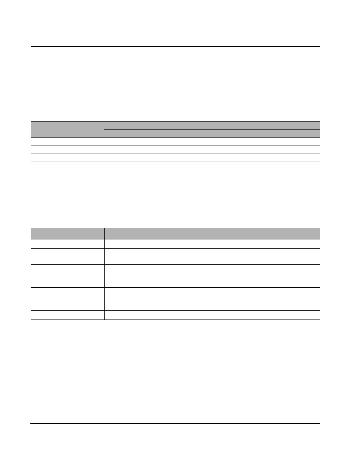
Table 2: Wire Selection Table
3) Tamper Switch
A tamper switch is required to be installed on the 505ULAC/510ULAC that will monitor the
enclosure for unauthorized access. The tamper switch should be attached to a UL Listed burglar
alarm system or a Listed local siren/annunciator. This will allow for compliance to UL294 Section
32.1.4.
Total Length of One Wire Run
(Feet) Load Current @ 12VDC Load Current @ 24VDC
1/4A 1/2A 3/4A 1A 1/4A 1/2A 3/4A 1A
100 24 18 16 14 24 20 18 18
200 16 14 12 12 20 18 16 14
300 16 12 12 10 18 16 14 12
400 14 12 10 -- 18 14 12 12
500 14 10 10 -- 16 14 12 10
505ULAC Installation Instructions
Installing the 505ULAC
23392707-B Page 6 03-2009
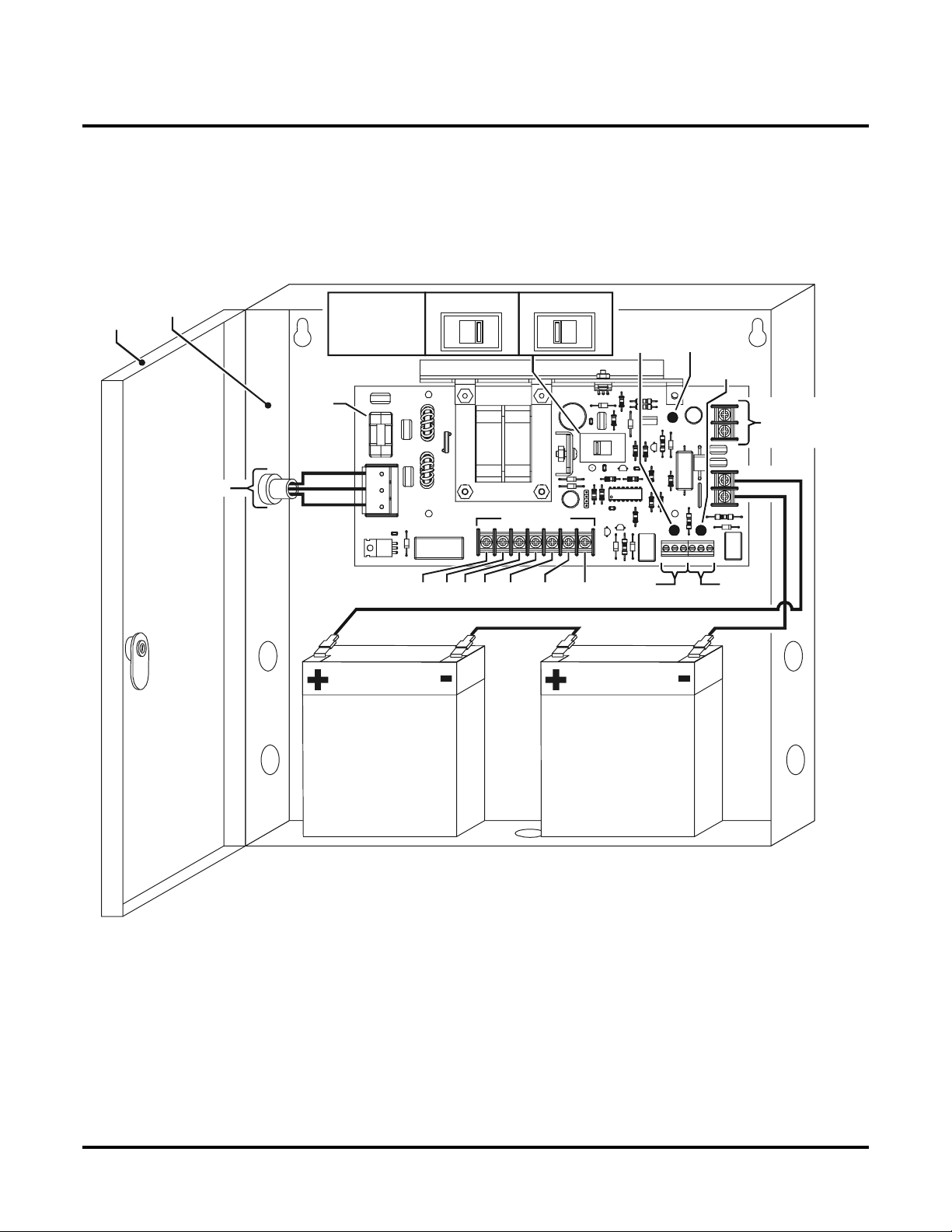
Installation Diagram
Refer to the diagram below when wiring the 505ULAC Power Supply. Stand-by batteries shown
for 24VDC operation and are wired in series.
Figure: 1. Installation Diagram
WARNING: De-energize unit prior to servicing. For continued protection against fire haz-
ard, replace fuse (F1) with the same type and rating (800mA, Slo-Blo, 250V). Replace fuse
cover before energizing.
NC C NONC C NO
F1
SW1
VOLTAGE
SELECTION
24VDC12VDC
Battery 1 Battery 2
WHITE
DOOR
110 VAC INPUT
DC OUTPUT
TO DEVICES
(power limited)
BLACK
ENCLOSURE
BATTERY
FAIL
Supervision Circuit
(power limited)
AC
FAIL
GREEN
BATTERY
MONITOR
(GREEN)
DC
OUTPUT
(RED) AC
MONITOR
(GREEN)
EIR IN C NO NC -OUT +OUT
EIR ALARM
BAT
( )
+
BAT
( )
-
BATTERY CONNECTION SHOWN FOR 24VDC OPERATION.
505ULAC Installation Instructions
Stand-by Battery Installation / Terminal Identification
23392707-B Page 7 03-2009
Stand-by Battery Installation / Terminal Identification
Stand-by Battery Installation
1.) Verify field wiring is complete.
2.) Place batteries upright in bottom of enclosure (See Installation Diagram on page 6).
3.) Using the provided cables, connect batteries (See Installation Diagram on page 6).
4.) Turn on VAC line power input to power supply.
Table 3: Stand-by Battery Power Selection Chart
NOTE: Charging time is approximately 48 hours from deep discharge.
Terminal Identification
Table 4: Terminal Identification
Current Load Draw (Amps) 12VDC SYSTEM 24VDC SYSTEM
Hours Hours Hours Hours
1481648
0.5 8 16 32 8 16
0.33 12 24 48 12 24
0.22 18 36 72 18 36
0.16 25 50 100 25 50
Number of batteries required 1 2 4 2 4
Terminal Legend Function / Description
Line, Ground, Neutral 110VAC, 50/60Hz input
DC (-), DC (+) 12VDC @ 1A continuous power limited output
24VDC @ 1A continuous power limited output
AC Fail
NC C NO Indicates loss of AC power, e.g. connect to alarm panel.
Relay normally energized when AC power is present.
Contact rating: 1A @ 28VDC
Battery Fail
NO C NC Indicates low battery voltage, e.g. connect to alarm panel.
Relay normally energized when DC power is present.
Contact rating: 1A @ 28VDC
BAT (-), BAT (+) Stand-by battery connections

505ULAC Installation Instructions
EIR Connection / LED Diagnostics / Maintenance
23392707-B Page 8 03-2009
EIR Connection / LED Diagnostics / Maintenance
EIR Connection
The purpose of the EIR circuit is to cut power to fail safe locks in an emergency situation. When
using the EIR relay circuit to supply power to fail safe locks, such as electromagnetic locks,
power must come from connector J6, terminals: -OUT & +OUT as shown below. Be sure to test
all circuits for proper function after installation.
Figure: 2. EIR Connection
LED Diagnostics Table 5: LED Diagnostics
Maintenance
Unit should be tested at least once a year for proper operation. Perform test as follows:
Output Voltage Test - Under normal load conditions, the DC output voltage should be checked
for proper voltage level (see power supply voltage output in the Product Specifications Chart).
Battery Test - Under normal load conditions, check the following
• Battery is fully charged.
• Specified voltage at all battery terminals and PCB terminals marked BAT (+) & BAT (-).
This ensures there are no breaks in the battery cables.
NOTE: Expected battery life is 5 years. Change batteries every 4 years, or less if necessary.
DC OUTPUT
(RED) AC MONITOR
(GREEN BATTERY MONITOR
(GREEN) POWER SUPPLY STATUS
ON ON ON Normal Operation.
ON ON OFF Batteries Disconnected or Discharged.
ON OFF ON Unit on Back-up Battery.
OFF ON OFF DC Output Shorted.
OFF OFF OFF Unit De-energized.
NORMALLY CLOSED DRY CONTACT FROM
FIRE PANEL (BY OTHERS). CONTACT MUST
OPEN UPON EMERGENCY. NOTE: IF THIS IS
NOT USED, TERMINALS: “EIR” & “IN”
MUST BE JUMPERED.
OUTPUT POWER TO LOCKING SYSTEM WILL
HAVE GROUND CONNECTION (-) REMOVED
WHEN FIRE ALARM CONTACT OPENS ON TER-
MINALS: “EIR” & “IN”.
RELAY OUTPUT REFLECTS CONDITION OF EIR RELAY
FOR SIGNAL OR CONTROL. RATED 5 A @ 30VDC.
J6 EIR Alarm
EIR IN C NO NC -OUT +OUT
This manual suits for next models
1
Table of contents
Other Schlage Power Supply manuals


Popular Power Supply manuals by other brands


Pyramid
Pyramid PS-9KX instruction manual

Whelen Engineering Company
Whelen Engineering Company CSP69024 installation guide

ICT
ICT PRT-PSU-DIN-2A installation manual

elsner elektronik
elsner elektronik KNX PS640-IP 2U installation instructions

PR electronics
PR electronics 2220 manual

Juniper
Juniper SRX 3400 installation instructions


