Schlagel VGC User guide

SCHLAGEL, INC.
VGC Gate Control
Page 1
Other manuals available for the VGC are:
Operating And Customizing The VGC
Installing VGC Sensors On An Electric Gate
Operating The VGC From A PLC.
These instructions apply to an electric gate with the VGC sensors properly mounted. See the separate manual
Installing VGC Sensors On An Electric Gate if the sensor installation is incomplete.
The VGC includes all of the necessary electrical control components to operate the gate. A 20 VAC supply is
required for power. The standard 3 Phase C-Face motor is powered by the VGC inverter and the gate position is read
by two inductive sensors. These two sensors are connected to a barrier relay allowing intrinsically safe wiring
practice. Much of the high reliability of the VGC system is the result of the elimination of mechanical switches.
The location of the components is site specific but generally the gate, electric drive package and VGC Panel are
usually in different areas. Keep in mind that convenient access to the drive components is valuable when
troubleshooting a problem. When more than one drive is being installed, using a single enclosure for all drives may
be the most convenient method for mounting the drives. We can supply NEMA 2 enclosures for multiple drives or
mounting panel for grouping the VGC Panels on request.
This manual covers the following subjects:
• How it works
• Connecting the electrical components
• Testing the connections
• Running the gate manually
• Running the Learn Mode routine
• VGC Specifications
VGC
Installation And Setup Manual
Pat. Pend.

SCHLAGEL, INC.
VGC Gate Control
Page 2
How It Works
Closed position (CP) sensor location. Target Wheel (TW) sensor location.
Two inductive sensors collect all of the necessary gate position data. The illustrations above show their
location within the gate. These sensors are Intrinsically Safe when wired in accordance with the governing
code authority.
The CP sensor cable is mounted inside the gate and activates when the slide is fully closed. The CP cable is
routed to the outside of the gate through the nipple, then into the junction box. The TW sensor is mounted
to the reducer output shaft and monitors the shaft rotation. Its cable goes directly to the junction box. A
field supplied 4-wire cable runs from the junction box to the barrier relay allowing Intrinsically Safe wiring
practice. The barrier relay provides the power for the IS sensor circuit.
The motor is a /2 Hp 3 phase motor wired for 220 Volts. The motor may be ordered as TENV or
explosion proof. An inverter that uses a 0 Volt supply powers the motor.
A 3” x 3” microprocessor-based VGC Panel includes a gate position display as well as the pushbuttons and
positioning potentiometer. The VGC Panel is usually mounted in a control room. This control reads the
sensors and has full control of the inverter. It is connected to the inverter using a 0-wire ribbon cable. The
control is fully enabled to communicate with up to 20 other VGC gates and EDI distributors through our
UIO Interface. The UIO communicates via Ethernet or serial with the PLC to allow full control or just
monitoring of all of these devices.
The inverter and barrier relay are shipped mounted on a backplane suitable for installing in a 0 x 2
NEMA 2 enclosure. A backplane holding the inverters and barrier relays for 2 VGC drives can be
mounted in a 0 x 6 NEMA 2 enclosure. Enclosures are available from our stock.
We can supply precut VGC Panel mounting matrixes in just about any combination. Please call us for this
or any technical information you may need.
Failure to comply with the wiring instructions in this doc
ument could lead to improper operation,
equipment damage or serious injury or death.
The VG control should only be installed and wired by an experienced electrician. Make sure the
wiring meets all applicable regulations and codes including local and national standards and codes.
High voltage can kill or seriously injure personnel. All maintenance personnel must be trained and
follow the proper Lockout/Tagout procedures established by the facility management.

SCHLAGEL, INC.
VGC Gate Control
Page 3
VG Electrical onnections
There are 4 electrical connections to make for each VGC control. A more detailed discussion of each
connection will follow these descriptions
Item Description
20-volt supply to the inverter.
2 230-volt 3 phase connection from the inverter to the gate motor.
3 A 4-wire cable from the barrier relay to the gate junction box. 4000’ maximum length. This is an
Intrinsically Safe circuit.
4 A 0-wire flat or round ribbon cable from the inverter to the VGC Panel. 400’ Max.
Refer to the pictorials on the previous page for a complete layout of the electrical connections.
Item 1. The power input is a 20-volt 0 Amp supply. This is usually supplied by individual breakers in a
breaker sub-panel.
Item 2. The inverter output to the motor is 230-volt 2.4 Amp 3 Phase. Attention to motor direction is not
required. Since this connection carries variable frequency from the inverter it is generally advisable to
keep its length less than 200’. If it must be greater than 200’ please contact us for recommendations.
Item 3. This 4-wire cable is used to connect the barrier relay to the sensors and may be up to 4000’ in
length. Any type of 4 wire cable is suitable – e.g. thermostat wire – and can be confined in a conduit
with other IS wiring. This circuit is classified as Intrinsically Safe (IS). It can be run as open wiring in
Cls II, Grps E,F,G hazardous locations. It cannot be allowed to run in raceways with power wiring or
be close in proximity with non-IS wiring. Follow the jurisdictional codes for IS wiring.
Item 4. A 5’ long flat cable with suitable connectors on each end is supplied with each VGC. We have
satisfactorily tested operation with cables over 400’ long. A round ribbon cable approximately .275”
dia. can also be provided in any length. It uses the same field applied connectors as the flat cable.
Although this cable carries only low voltage, low current power, it is NOT Intrinsically Safe.

SCHLAGEL, INC.
VGC Gate Control
Page 4
Sensor to Barrier Relay onnections
There are 2 sensors at the gate: The closed position (CP) sensor and the target wheel sensor (TW). Each
sensor has 2 wires: brown and brown/blue. It is important that these 4 wires are connected properly to the
barrier relay (BR) terminals.
The CP sensor brown wire to BR-
The CP sensor brown/blue wire to BR-4
The TW sensor brown wire to BR-2
The TW sensor brown/blue wire to BR-5
The barrier relay has 8 switches on its top face. All switches should be right EXCEPT the first or top switch
should be left.
Power heck
You may want to remove the Control from its permanent location and temporarily connect it to the drive
using the supplied 5’ ribbon cable for testing and setup.
Remove the ribbon cable to the VGC Panel from the connector on the inverter. This will prevent the gate
from moving when power is applied.
Apply power to the 20-volt circuit. The green Pwr LED on the BR should be lit.
There should be no red LEDs showing.
BR-Led- and BR-Led-2 may be yellow or off (but it must not be red).
If any of the above conditions are wrong, the sensors are improperly wired to the barrier relay or the
switches are improperly set. Correct the connections and re-do this power check.
AUTION! Be sure that moving the gate will not cause personal injury to someone near the gate.
Also make sure that opening the gate will not allow bulk product to mistakenly flow thru the gate.

SCHLAGEL, INC.
VGC Gate Control
Page 5
Testing Gate Motion
The following instructions will allow you to electrically operate the gate with the push buttons on the VGC
Panel. No position readout is available until the control has been configured in Learn Mode but gate
movement and sensor operation can be visually observed using the LED on the front of the control. In
Manual Mode you can make small positioning adjustments to check sensor operation or just position the
gate manually until a full configuration can be made at a later date.
Remove the power to the VGC drive.
Note: I you don’t know i the VGC Panel you are working with has been previously programmed, hold
the CLOSE button during the irst power-up to ensure the control is in Manual Mode. Once in Manual
Mode, it will always power-up to Manual Mode until the installer per orms the escape sequence. This
sequence will be explained near the end o these installation instructions.
Re-attach the VGC Panel to the inverter using the ribbon cable. Apply power to the drive.
The Control will display ’<- MANUAL MODE ->’ on the second line. You now have electrical control of
the gate movement using the VGC Panel pushbuttons.
Pressing the OPEN and CLOSE pushbuttons will move the gate in opposite directions. At this time the
control is not aware of the actual motor-rotation/gate-direction so OPEN and CLOSE have no literal
meaning. You can just ‘bump’ the gate a bit with the push buttons until you can establish if the direction of
the gate matches the push button name. The motor direction will be automatically compensated for during
the Learn Mode. If you will be using the gate in Manual Mode for sometime, you may want to electrically
change the motor rotation to match the push button description.
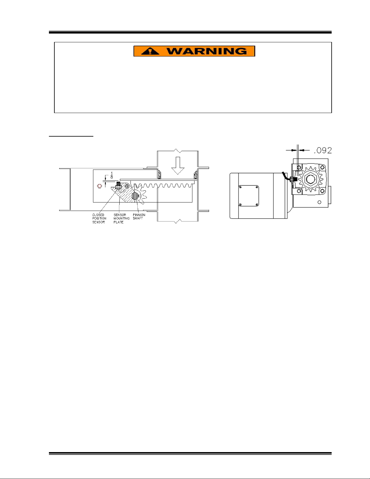
Fully close the gate. The LED should be in State . If not, the closed position sensor is miswired, has the
wrong barrier relay switch settings or is improperly adjusted.
Slightly open the gate about /4”. The LED should be in State 2. Again, check the close sensor if this is not
correct.
Depress and hold the OPEN button so the gate opens fully. During this time the LED should be in State 3.
The blinking pattern is reflecting the target wheel sensor state.
When the gate finishes its opening travel limit, the LED will return to State 2.
As a final check, the following two rules apply to the LED indicators on the barrier relay:
1. Lamp 1 must be yellow ONLY when the gate is fully closed. Lamp 1 must be off whenever
the gate is NOT fully closed.
2. Lamp 2 must blink yellow to off when the gate is moving.
If any of these conditions are not met, correct them before continuing.
AUTION! Be sure that moving the gate will not cause personal injury to someone near the gate.
Also make sure that opening the gate will not allow bulk product to mistakenly flow thru the gate.
The multi-colored LED at the top of the VGC Panel is used in Manual Mode to check the gate and
sensor operation. The colors and blink pattern have special meaning.
State : A steady Green state indicates the gate is fully closed.
State 2: A steady Yellow, Red, or off, indicates the gate is not closed.
State 3: A blinking pattern with State 2 colors means the gate is moving.

SCHLAGEL, INC.
VGC Gate Control
Page 6
Learn Mode
The Learn Mode exercises the gate to find, and record in its memory, the motor rotation and length of gate
travel. For this reason, the VGC Panel that will be assigned to this gate must be used during the setup. For
convenient access you may remove the Control from its permanent location and connect it to the drive
using the supplied 5’ ribbon cable.
You will now escape the Manual Mode so that the control may be used to begin the Learn Mode routine.
Press and hold both OPEN and CLOSE buttons at the same time, Release these buttons when prompted to do
so.
If you are using an un-programmed control, the screen will display “LEARN MODE” on the first line and
“PRESS OPEN” on the second line.
- or -
if the control was previously programmed, press and hold the OPEN button during reset or power-up to
enter Learn Mode.
Momentarily press the OPEN button when you want the Learn Mode routine to start.
The gate will move back and forth, testing the sprocket sensor adjustment, motor rotation, travel limits and
the closed position limit switch. Upon successful completion, a percent value and count value will be
shown on line 2 of the display. Make a note of the percent number. It should be between 60% and 0%, the
closer to 0% the better the adjustment is. If it is greater than 60%, the sprocket sensor will need adjustment.
If the routine fails, return to page 5 to test the gate setup..
If there were no errors during Learn Mode, the information gathered from this routine will be stored in
permanent memory in the VGC Panel. The VGC Panel may be returned to its permanent location.
Refer to the Operating And Customizing The VGC manual to operate the gate and customize the VGC
Panel.
AUTION! Be sure that moving the gate will not cause personal injury to someone near the gate.
Also make sure that opening the gate will not allow bulk product to mistakenly flow thru the gate.

SCHLAGEL, INC.
VGC Gate Control
Page 7
VG Specifications
*Note: Roller chain reductions may be used to increase force at the cost of s eed.
*Drill 5/32 dia. for #6 screw clearance.
*Drill 7/64 dia. for #6 self threading screw.
VG Drive omponents
Motor
.5 HP, 750 RPM, 220 Volt 3 Phase 56 C-Face
Gear Reducer
00: Worm gear, ” dia. adjustable clutch driven output shaft
Inverter input
20 Volt, single phase. Full load current draw 3.6 Amp
Gate Force & Speed - Direct Shaft Drive, 11 Tooth Pinion*
Gate travel speed
2.4 In/Sec
Gate force
Adjustable 0 to 800 Lbs. (
See Note.)
Travel
in. to over 00 ft.
VG Panel
Size
3” x 3” x ” deep
Power
Supplied by the inverter within 0 wire ribbon control cable
Display
2 character, 2 line LCD, Multicolored LED
Operators
OPEN and CLOSE pushbuttons, Positioning potentiometer
Communication Onboard EDINet (RS-485) for UIO network messaging is standard.

SCHLAGEL, INC.
VGC Gate Control
Page 8
Schlagel, Inc.
4 1 N. Emerson
Cambridge MN 55008
763-68 -5 1
800-328-8002
Fax 763-68 -5310
www.schlagel.com
Table of contents
Popular Gate Opener manuals by other brands

BFT
BFT ELI BT A35 V Installation and user manual

BFT
BFT ARES Installation and user manual

Chamberlain
Chamberlain SL3000U installation manual

PPA
PPA BV POTENZA PREDIAL CUSTOM Technical manual

Serai
Serai KIT 45 Installer manual

Platinum Access Systems
Platinum Access Systems BLSW1016 Installation instruction and owenrs manual