For special versions, which are not listed in the ordering code, these specifications apply accordingly, provided that
they correspond to the standard version.
2.3 Purpose
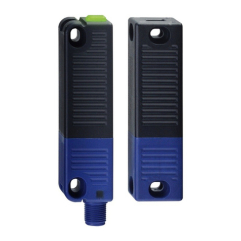
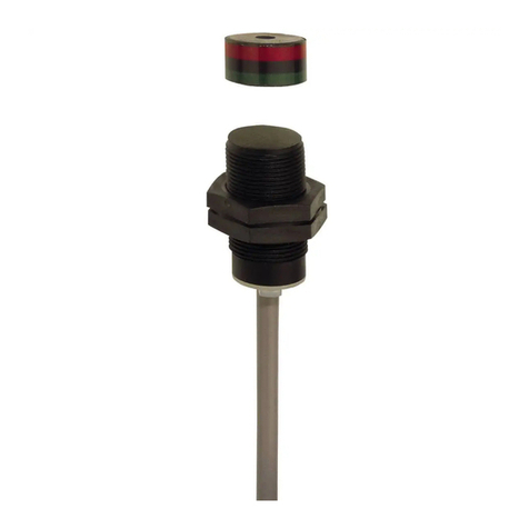
This non-contact, electronic safety sensor is designed for application in safety circuits and is used for monitoring the
position of movable safety guards. In this application, the safety sensor monitors the position of hinged, sliding or
removable safety guards by means of the coded electronic actuator.
The safety function consists of safely switching off the safety outputs when the safety guard is opened and
maintaining the safe switched off condition of the safety outputs for as long as the safety guard is open.
FThe safety switchgears are classified according to EN ISO 14119 as type 4 interlocking devices. Designs with individual
coding are classified as highly coded.
Mit der Option F0/F1 übernimmt der Sensor Aufgaben eines Sicherheitsrelaisbausteins. An die beiden
Sicherheitsausgänge lassen sich zwei Hilfsschütze1) oder Relais1) (1) jeweils mit zwangsgeführten Kontakten nach
EN 60947-5-1 bzw. EN 50205) anschließen, deren sicherheitsgerichtete Funktion mit Hilfe eines Rückführkreises
vom Sensor überprüft wird (External Device Monitoring). Der Rückführkreis beinhaltet die Reihenschaltung der
Öffnerkontakte der Hilfsschütze oder Relais. In der Ausführung F0 kann zusätzlich ein „Freigabetaster" (ohne
Sicherheitsfunktion) in den Rückführkreis geschaltet werden. In der Ausführung F1 ist ein „Reset-Taster" notwendig,
der auf eine fallende Flanke hin überwacht wird. Diese Funktion entspricht der „Manuellen Rückstellfunktion" nach
EN ISO 13849-1.
Mit der Option Q wird das gleichzeitige Abschalten der Sensoreingänge überwacht. Bei einer Sensor-
Reihenschaltung ermöglicht dies die Einbindung von NOT-HALT-Schaltelementen für Anwendungen bis PL e. Die
NOT-HALT-Kontakte werden von den querschlussüberwachten Ausgangssignalen eines vorgeschalteten
elektronischen Sicherheitsschaltgerätes versorgt. Am Ende der Kette überwacht ein Sensor mit Option Q zum
Anschluss einer Quittierfunktion die Kette auf synchrones Abschalten beider Kanäle. Bei fehlerhaftem Abschalten
muss der Fehler behoben werden. Die Sicherheitsausgänge lassen sich erst nach Fehlerquittierung wieder
aktivieren.
The diagnostic output of the safety sensor alternatively can be used as a conventional output or as a “serial output“
with input and output channel.
Series-wiring
Series-wiring can be set up. In the case of a series connection, the risk time remains unchanged and the reaction
time increases by the sum of the reaction time of the inputs per additional unit specified in the technical data. The
quantity of devices is only limited by the cable drops and the external cable fuse protection, according to the
technical data. Up to 31 device variants with serial diagnostics can be wired in series.
2The user must evaluate and design the safety chain in accordance with the relevant standards and the required safety
level. If multiple safety sensors are involved in the same safety function, the PFH values of the individual components must
be added.
2The entire concept of the control system, in which the safety component is integrated, must be validated to the relevant
standards.
2.4 Warning about misuse
4-27
