6 Actuator coding
Safety sensors with standard coding are ready to use upon delivery.
Individually coded safety sensors and actuators will require the following "teach-in" procedure:
1. Energise the safety sensor.
2. Introduce the actuator in the detection range. The teach-in procedure is signalled at the safety sensor, red
LED on, yellow LED flashes (1 Hz).
3. After 10 seconds, brief yellow cyclic flashes (3 Hz) request the switch-off of the operating voltage of the
solenoid interlock. (If the voltage is not switched off within 5 minutes, the safety sensor cancels the "teach-
in" procedure and signals a false actuator by 5 red flashes).
4. Once the operating voltage is switched back on, the actuator must be detected once more in order to
activate the actuator code that has been taught in. In this way, the activated code is definitively saved!
Vid beställningsalternativ -I1 är den tilldelning som skapats av säkerhetslåset irreversibel.
Vid beställningsalternativ -I2 kan förfarandet för inlärning av en ny transponder upprepas ett obegränsat antal
gånger. Vid inlärning av en ny transponder blir den dittillsvarande koden ogiltig. I anslutning till detta garanterar en
tio minuter lång fördröjningstid ett ökat manipulationsskydd. Den gröna lysdioden blinkar tills tiden för
fördröjningstiden har löpt ut och den nya transpondern har detekterats. Vid spänningsavbrott under tidsförloppet
startar den 10 minuter långa fördröjningstiden på nytt.
7 Working principle and diagnostic function
7.1 Arbetssätt för säkerhetsutgångar
Säkerhetsutgångarna kan användas direkt för en koppling i den säkerhetsrelevanta delen av användarstyrningen.
Öppning av en skyddsdörr, dvs. borttagning av transpondern ur sensorns aktiva zon, medför en omedelbar
frånkoppling av säkerhetsutgångarna.
7.2 Diagnos-LED-lampor
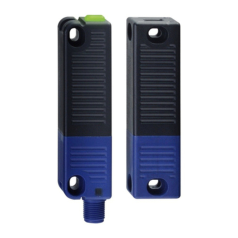
The safety sensor indicates the operating condition and faults by means of three-colour LEDs located in the lateral
surfaces of the sensor.
FThe following LED indicators are the same for safety sensors with conventional diagnostic output as for those with a serial
diagnostic function.
The green LED indicates that the safety sensor is ready for operation. The supply voltage is on and all safety inputs
are present.
Flashing (1Hz) of the green LED signals that a voltage is missing on one or both of the safety inputs (X1 and/or X2).
The yellow LED always signals the presence of an actuator within range. If the actuator is operating in the limit area
of the sensor switching distance, it will be indicated by flashing.
The flashing can be used to prematurely detect variations in the clearance between the sensor and the actuator
(e.g. sagging of a safety guard). The sensor must be adjusted before the distance to the actuator increases and
before the safety outputs are disabled, thus stopping the machine. If an error is detected, the red LED will be
activated.