INTERFERENCE PREVENTION FUNCTION
10
Emission
frequency
0.5ms or less
1
2
3
0.75ms or less
0.65ms or less
Response
time
٨
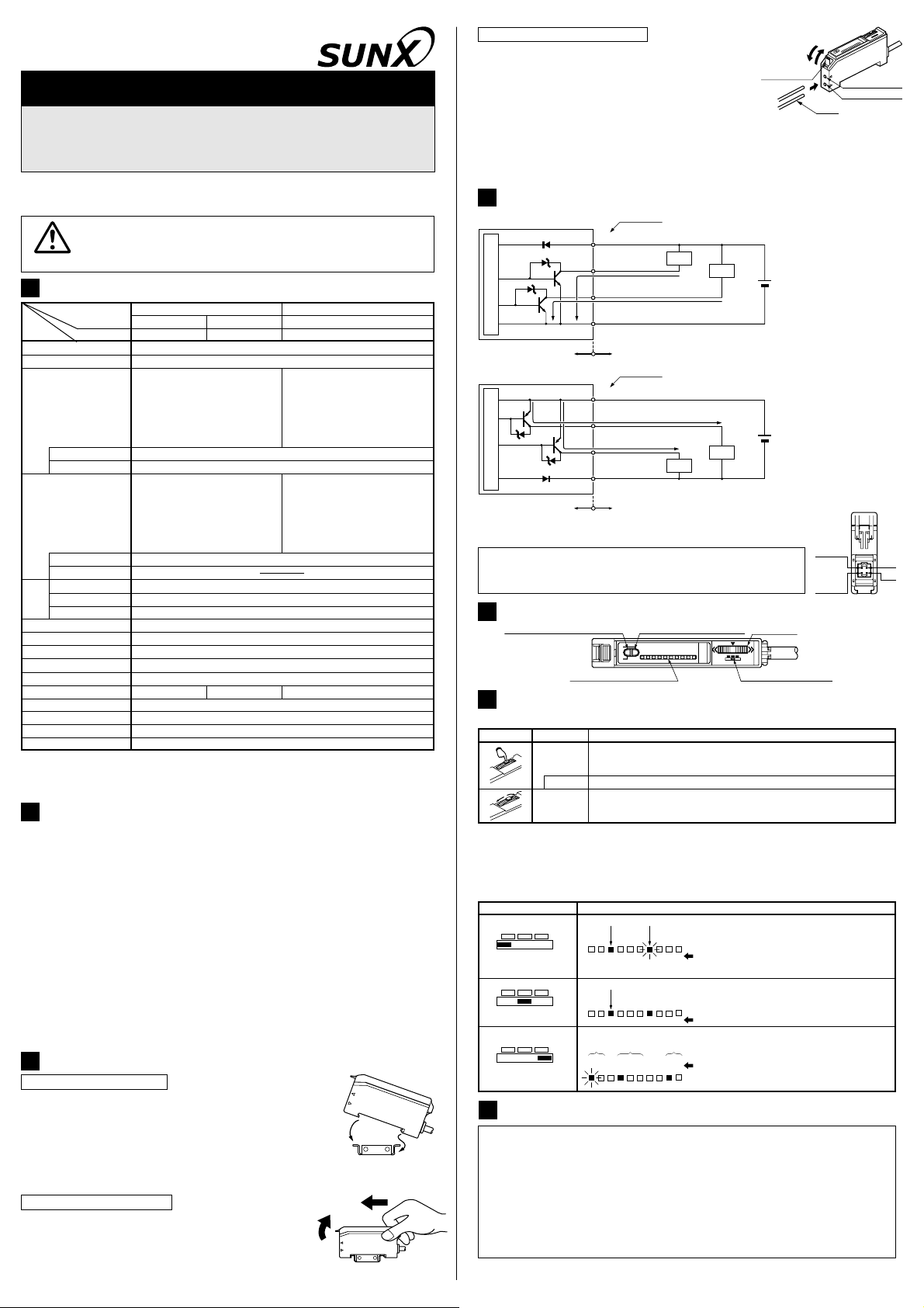
Since the FX-A1 series incorporate an interference prevention function, up to 3 sets of
fibers can be mounted close to each other by setting different emission frequencies.
Further, close mounting is also possible along with
fibers which are fitted to the fiber sensor amplifiers,
FX-D1 series and FX-M1 series.
Please refer to ' SETTING OF EACH MODE' for the
setting method.
However, note that the response time varies with the
emission frequency as given below.
8
Operation
٨
FX-A1 series incorporate an approx. 40ms fixed OFF-delay timer. Since the output is
extended by a fixed period, it is useful when the connected device has a slow response
time or when small objects are being sensed and the output signal width is small.
Please refer to ' SETTING OF EACH MODE' for the setting method.
8
TIMER FUNCTION
9
Timer period: T = 40ms approx.
<Time chart>
Light-ON
Normal
OFF-delay
timer
Dark-ON
Dark-ON
Light-ON
Output
operation
Timer
operation
Sensing
condition
ON
OFF
ON
OFF
ON
OFF
ON
OFF
Light
Dark
TT T
T
<Procedure for maximum sensitivity setting>
Ԙ
ԙ
Ԛ
ԛ
Ԝ
ԝ
Set the mode selection switch to 'SET'.
Press the jog switch in the condition when there is no object or background body.
The level indicators '4' and '5' blink after receiving the teaching.
Once again, press the jog switch in the condition when there is no object or background body.
The level indicator '9' blinks.
Set the mode selection switch to 'RUN'.
Note: Please take care that, if the sensor is set to max. sensitivity, it becomes weak against
extraneous light, noise and optical interference.
PRINTED IN JAPAN
Head Office
2431-1 Ushiyama-cho, Kasugai-shi, Aichi, 486-0901, Japan
Phone: +81-(0)568-33-7211 FAX: +81-(0)568-33-2631
Overseas Sales Dept.
Phone: +81-(0)568-33-7861 FAX: +81-(0)568-33-8591
http://www.sunx.co.jp/
SUNX Limited
SELF-DIAGNOSIS FUNCTION
11
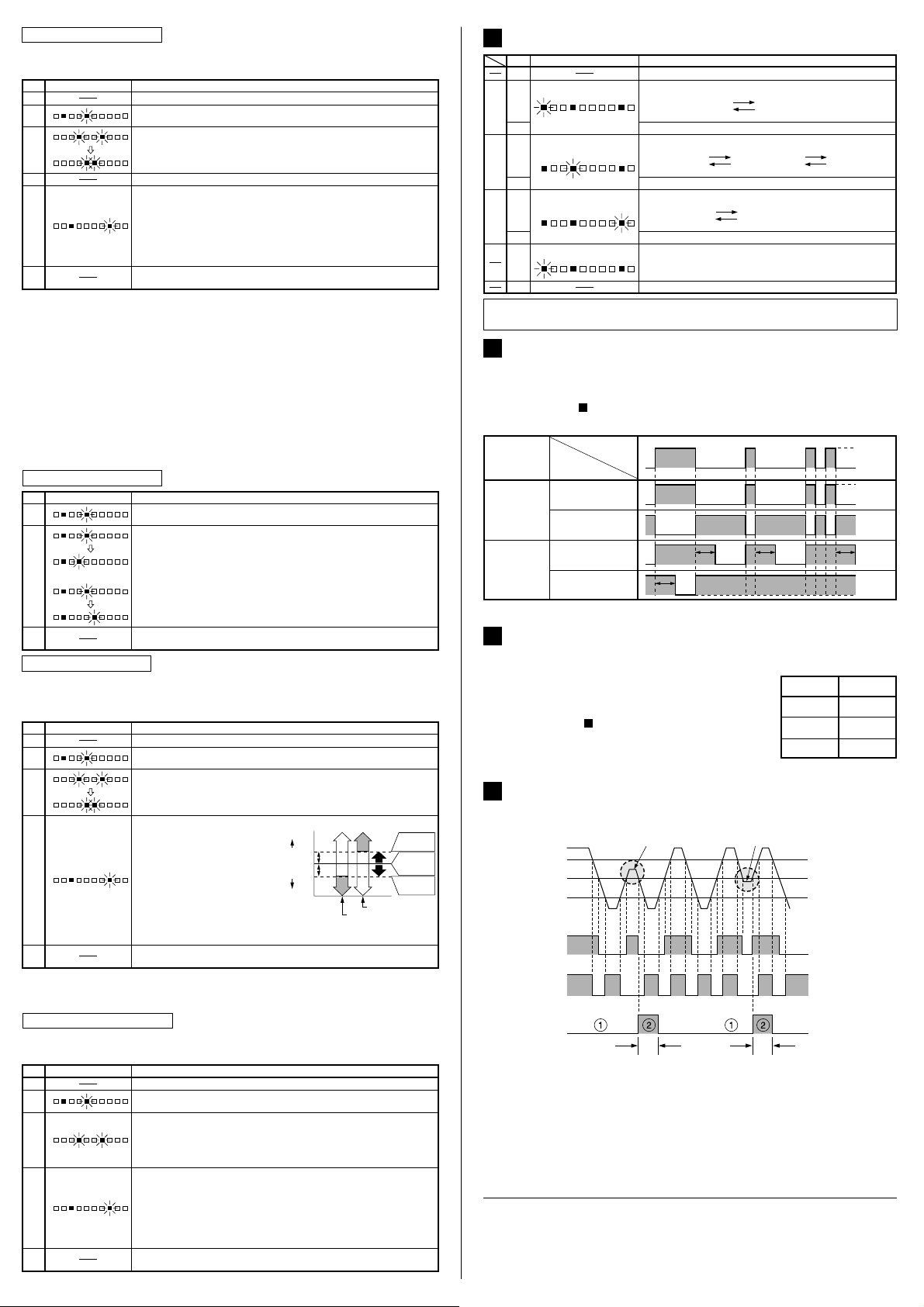
٨This is a function which diagnoses a decrease in the incident light intensity due
to dirt or dust, or optical misalignment, and gives an output.
Ԙ
ԙ
The self-diagnosis output transistor stays in the 'OFF' state during stable sensing.
When the sensing output changes, if the incident light intensity does not reach
the stable light level or the stable dark level, the self-diagnosis output becomes
'ON'. It automatically turns 'OFF' after 40ms approx. (Emission frequency 2:
50ms approx., Emission frequency 3: 60ms approx.)
Further, the self-diagnosis output is generated at the time when the sensing
output changes from 'ON' to 'OFF' or from 'OFF' to 'ON'.
(The operation of the sensing output is not affected.)
Sensing condition Sensing output
threshold level
ON (Lights up)
OFF (Lights off)
ON
OFF
Lights up
Lights off
Stable Dark level
Stable Light level
Insufficient beam intensity Insufficient beam interruption
Stability indicator
Self-diagnosis output
40ms approx. 40ms approx.
Sensing output
(Operation indicator)
(in the Light-ON mode)
ԝ
The jog switch is pressed in the object absent condition.
Ԝ
ԛ
Set the mode selection switch to 'SET'.
The present sensitivity setting is displayed.
Set the mode selection switch to 'RUN'.
The sensitivity level does not change even if the jog switch is operated.
Press the jog switch in the object present condition. The level indicators
'3' and '6' blink.
Release the jog switch within 3 sec. The level indicators '4' and '5' blink and
the incident light intensity in the object present condition is read. (Note)
Ԛ
Level indicators OperationStep
Ԙ
Set the fiber within the sensing range.
ԙ
9
8
7
6
5
4
3
2
1
0
9
8
7
6
5
4
3
2
1
0
9
8
7
6
5
4
3
2
1
0
9
8
7
6
5
4
3
2
1
0
The stability indicator (green) lights up and the sensitivity level is set at the
middle value of the incident light intensity levels in the object present and object
absent conditions. The sensitivity level is then displayed on the level indicators.
Hundreds position: lights up continuously, Tens position: blinks,
Units position: not shown
Example: The level indicators in the figure on the left show that the
sensitivity level is in the range 720 to 729.
Note: If the jog switch is pressed continuously for 3 sec., or more, full auto-teaching is done.
Also, if the mode selection switch is changed to 'RUN' while level indicators '4' and '5' are
blinking, the incident light intensity taught at Step Ԛis not recorded.
٨
This is the method of setting the sensitivity by teaching two levels, corresponding to the
object present and object absent conditions. Normally, setting is done as given below.
In case of 2-level teaching
Set the mode selection switch to 'RUN'.
The sensitivity level does not change even if the jog switch is operated.
The stability indicator (green) lights up and the sensitivity level is set at the
middle value of the incident light intensity levels in the object present and object
absent conditions. The sensitivity level is then displayed on the level indicators.
Hundreds position: lights up continuously, Tens position: blinks,
Units position: not shown
Example: The level indicators in the figure on the left show that the
sensitivity level is in the range 720 to 729.
Ԝ
ԛ
Set the mode selection switch to 'SET'.
The present sensitivity setting is displayed.
Press the jog switch continuously for 3 sec., or more, with the object
moving on the assembly line.
When the jog switch is pressed, the level indicators '3' and '6' blink and
when it is pressed continuously for 3 sec., or more, they start blinking
rapidly. Then, release the jog switch when the object has passed.
Ԛ
Level indicators OperationStep
Ԙ
Set the fiber within the sensing range.
ԙ
9
8
7
6
5
4
3
2
1
0
9
8
7
6
5
4
3
2
1
0
9
8
7
6
5
4
3
2
1
0
٨Full auto-teaching is used when it is desired to set the sensitivity without stopping
the assembly line, with the object in the moving condition.
In case of full auto-teaching
Set the mode selection switch to 'SET'.
The present sensitivity setting is displayed.
In case the sensitivity is to be increased, turn the jog switch a little to
the '+' side to increase the sensitivity slowly. If the jog switch is turned
fully to the '+' side, the sensitivity increases rapidly.
In case the sensitivity is to be decreased, turn the jog switch a little to
the '
-
' side to decrease the sensitivity slowly. If the jog switch is turned
fully to the '
-
' side, the sensitivity decreases rapidly.
Set the mode selection switch to 'RUN'.
The sensitivity level does not change even if the jog switch is operated.
Ԛ
Level indicators OperationStep
Ԙ
ԙor
9
8
7
6
5
4
3
2
1
0
9
8
7
6
5
4
3
2
1
0
9
8
7
6
5
4
3
2
1
0
9
8
7
6
5
4
3
2
1
0
9
8
7
6
5
4
3
2
1
0
In case of fine adjustment
Ԝ
ԛ
Set the mode selection switch to 'SET'.
The present sensitivity setting is displayed.
Set the mode selection switch to 'RUN'.
The sensitivity level does not change even if the jog switch is operated.
Press the jog switch in the object absent condition. The level indicators
'3' and '6' blink.
Release the jog switch within 3 sec. The level indicators '4' and '5' blink and
the incident light intensity in the object present condition is read. (Note)
Ԛ
Level indicatorsStep
Ԙ
Set the fiber within the sensing range.
ԙ
9
8
7
6
5
4
3
2
1
0
9
8
7
6
5
4
3
2
1
0
9
8
7
6
5
4
3
2
1
0
9
8
7
6
5
4
3
2
1
0
Note: If the jog switch is pressed continuously for 3 sec., or more, full auto-teaching is done.
Also, if the mode selection switch is changed to 'RUN' while level indicators '4' and '5' are
blinking, the incident light intensity taught at Step Ԛis not recorded.
٨This is the method of setting the sensitivity by teaching only the object absent
condition (incident light stable condition). This is used for detection in presence of a
background body or for detection of small objects.
In case of limit teaching
Example: The level indicators in the figure on the left show that the
sensitivity level is in the range 720 to 729.
'+' side:
'
-
' side:
The sensitivity is increased
by 15% approx. with respect
to that set at Ԛ. Used in
case of thru-beam type fiber.
The sensitivity is decreased
by 15% approx. with respect
to that set at Ԛ. Used in
case of reflective type fiber.
Turn the jog switch to either the '+' or the '
-
' side.
15%
15%
100%
0
OFF
ON
Turn to '
-
' side
Turn to '+' side
Sensitivity
level
Sensitivity
level
Sensitivity
level with
object absent
OFF
ON
High
Sensitivity
level
Low
SETTING OF EACH MODE
8
In case only a part of the settings are to be changed, set the mode selection switch to 'RUN', at
the appropriate time, in the middle of the above procedure to make only the required changes.
Set the mode selection switch to 'RUN' after finishing the settings.
Ԡ
Ԟ
ԝ
Press the jog switch at the timer operation desired to be set.
Back to ԙ.
Turn the jog switch to either the '+' or the '
-
' side.
NON
(without timer)
OFD
(approx. 40ms fixed OFF-delay timer)
-
+
ԟ
L-ON
D-ON
FR1
FR2
FR3
NON
OFD
L-ON
D-ON
FR1
FR2
FR3
NON
OFD
Press the jog switch at the output operation desired to be set.
Ԛ
Level indicators DescriptionStep
Ԙ
Set the mode selection switch to 'MODE'.
ԙ
Ԝ
ԛ
Press the jog switch at the emission frequency desired to be set.
The mode being set blinks.
L-ON
D-ON
FR1
FR2
FR3
NON
OFD
L-ON
D-ON
FR1
FR2
FR3
NON
OFD
Turn the jog switch to either the '+' or the '
-
' side.
L-ON (Light-ON) D-ON (Dark-ON)
-
+
Turn the jog switch to either the '+' or the '
-
' side.
FR1
(Emission frequency 1)
FR3
(Emission frequency 3)
FR2
(Emission frequency 2)
-
+
-
+
Output oper-
ation setting
Timer oper-
ation setting
Emission fre-
quency setting