2
Operating instructions
Solenoid interlock EX-AZM 161
EN
1.7 Exclusion of liability
We shall accept no liability for damages and malfunctions resulting from
defective mounting or failure to comply with this operating instructions
manual. The manufacturer shall accept no liability for damages
resulting from the use of unauthorised spare parts or accessories.
For safety reasons, invasive work on the device as well as arbitrary
repairs, conversions and modifications to the device are strictly
forbidden; the manufacturer shall accept no liability for damages
resulting from such invasive work, arbitrary repairs, conversions and/or
modifications to the device.
2. Product description
2.1 Ordering code
This operating instructions manual applies to the following types:
EX-AZM 161➀-12/12-➁K➂-024-3D
No. Option Description
➀
SK Screw terminals
CC Cage clamps
➁
Latching force 5 N
R Latching force 30 N
➂
Power to unlock
A Power to lock
Only if the information described in this operating instructions
manual are realised correctly, the safety function and
therefore the compliance with the Machinery Directive and
the Explosion Protection Directive is maintained.
2.2 Special versions
For special versions, which are not listed in the order code below 2.1,
these specifications apply accordingly, provided that they correspond
to the standard version.
2.3 Purpose
The solenoid interlock has been designed to prevent in conjunction
with the control part of a machine, movable safety guards from being
opened before hazardous conditions have been eliminated. The
components can be used in potentially explosive atmospheres of
Zone 22 equipment category 3D. The installation and maintenance
requirements to the standard series EN 60079 must be met.
Interlocks with power to lock principle may only be used in
special cases after a thorough evaluation of the accident risk,
since the safety guard can be opened immediately on failure
of the power supply or upon activation of the main switch.
The safety switchgears are classified according to ISO 14119
as type 2 interlocking devices.
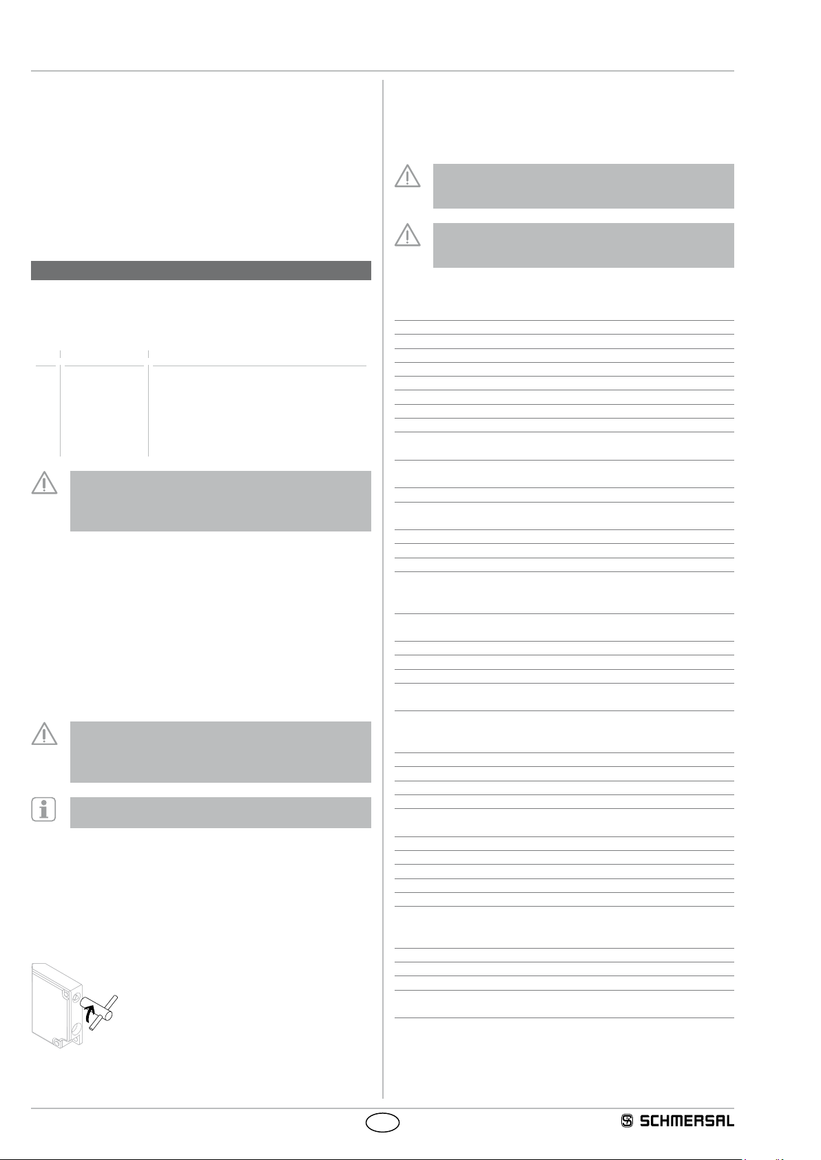
Manual release (for set-up, maintenance, etc.)
The manual release is realised by turning the triangular key (M5
triangular key available as accessory), so that the locking bolt is pulled
into the unlocking position. The normal locking function is only restored
after the triangular key has been returned to its original position. After
being put into operation, the manual release must be secured by
installing the plastic cover, which is included in delivery.
Manual release
Conditions for safe operation
Due to the specific impact energy, the components must be fitted
with a protection against mechanical stresses. The specific ambient
temperature range must be observed. The user must provide for a
protection against the permanent influence of UV rays.
The user must evaluate and design the safety chain in
accordance with the relevant standards and the required
safety level.
The entire concept of the control system, in which the safety
component is integrated, must be validated to the relevant
standards.
2.4 Technical data
Designation in accordance with the ATEX Directive: DII 3GD
Designation in accordance with standards: Ex tc IIIC T80°C Dc X
Applied standards: IEC 60947-5-1, EN 60079-0, EN 60079-31
Protective enclosure (option): Metal, coated
Actuator and locking bolt: stainless steel 1.4301
Contact material: Silver
Coding level according to ISO 14119: low
Ambient temperature: −10 °C … +50 °C
Protection class: IP67
Contact type: Change-over with double break Zb,
galvanically separated contact bridges
Applied standards:
B
IEC 60947-5-1, slow action,
NC contact with positive break
Positive break travel (unlocked): 9.5 mm
Positive break force (unlocked): 10 N for each NC contact
fitted
Connection: screw terminals or cage clamps
Cable section: 1.5 mm² (including conductor ferrules)
Cable entry: 4 x M16 x 1.5
Holding force:
- FZh: 2,000 N
- Fmax: 2,600 N
Latching force: 5 N
- Ordering suffix R: 30 N
Actuating speed: max. 1 m/s
Actuating frequency: max. 1,000 operations/h
Mechanical life: max. 1,000,000 million operations
Max. impact energy: without mechanical protective enclosure: 1 J
with mechanical enclosure: 7 J
Tightening torque:
- Cover screws: min. 0.6 Nm
- Cable gland / locking screws: 3 Nm
Cable glands:
D
II 2GD
Cable cross-section: min. Ø 5 mm, max. Ø 10 mm
Electrical data:
Utilisation category: AC-15, DC-13
Rated operating current/voltage Ie/Ue:4 A / 230 VAC
2.5 A / 24 VDC
Rated impulse withstand voltage Uimp:4 kV
Rated insulation voltage Ui:250 V
Thermal test current Ithe: 6 A
Max. fuse rating: 6 A gG D-fuse
Required rated short-circuit current: 1,000 A
Rated control voltage Us:24 VDC
24 VAC / 50/60 Hz
110 VAC / 50/60 Hz
Electrical data – Magnet control:
Magnet switch-on time: 100 %
Power consumption: max. 10 W
Accepted test pulse duration on input signal: ≤ 5.0 ms
- With test pulse interval of: ≥ 50 ms


