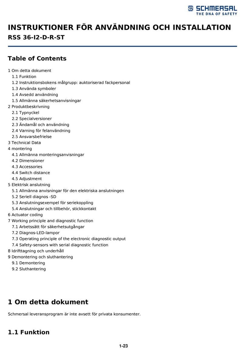
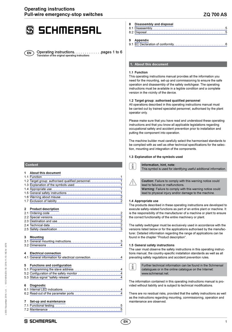
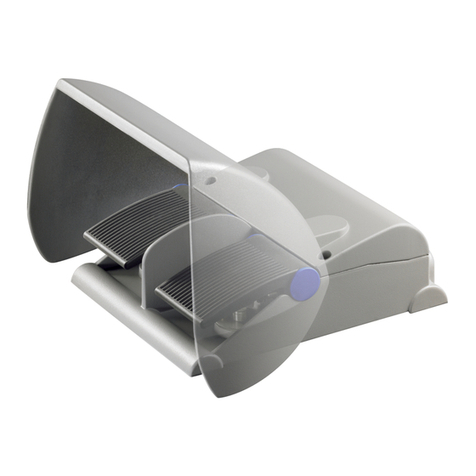
schmersal BN 310-2RZ User manual
Other schmersal Switch manuals
schmersal
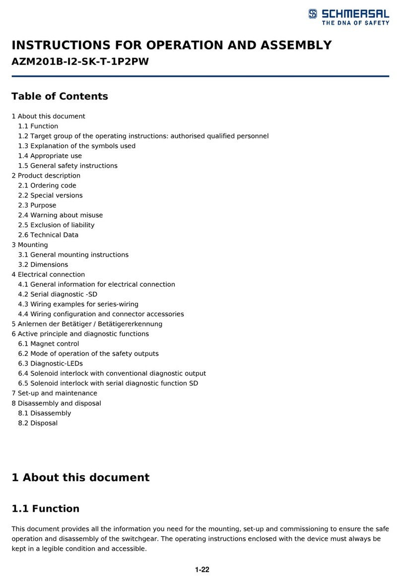
schmersal AZM201B-I2-SK-T-1P2PW Service manual

schmersal
schmersal AZ 200 User manual

schmersal
schmersal AZM300B-I1-ST-1P2P Operation and maintenance manual
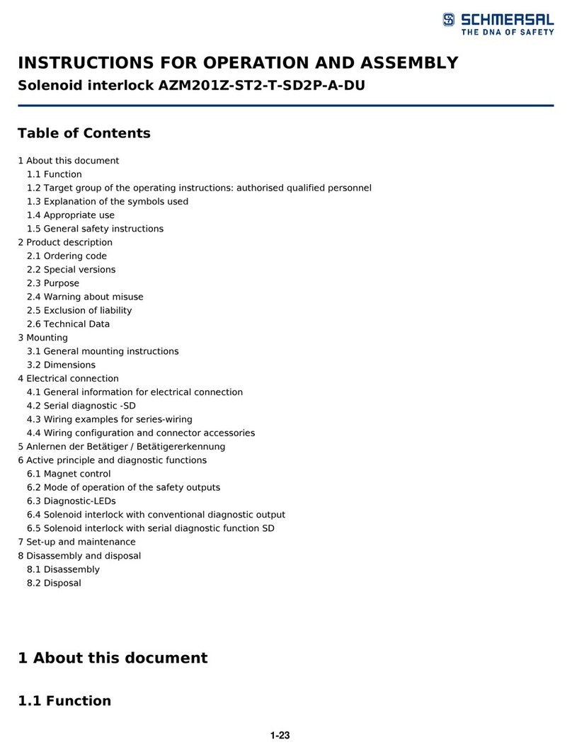
schmersal
schmersal AZM201Z-ST2-T-SD2P-A-DU Operation and maintenance manual

schmersal
schmersal EX-SHGV User manual

schmersal
schmersal AZM300B-ST-1P2P-N User manual

schmersal
schmersal AZM300B-ST-SD2P-T Operation and maintenance manual
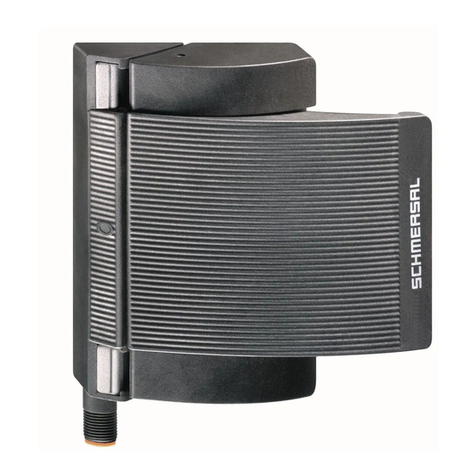
schmersal
schmersal BNS-B20 User manual
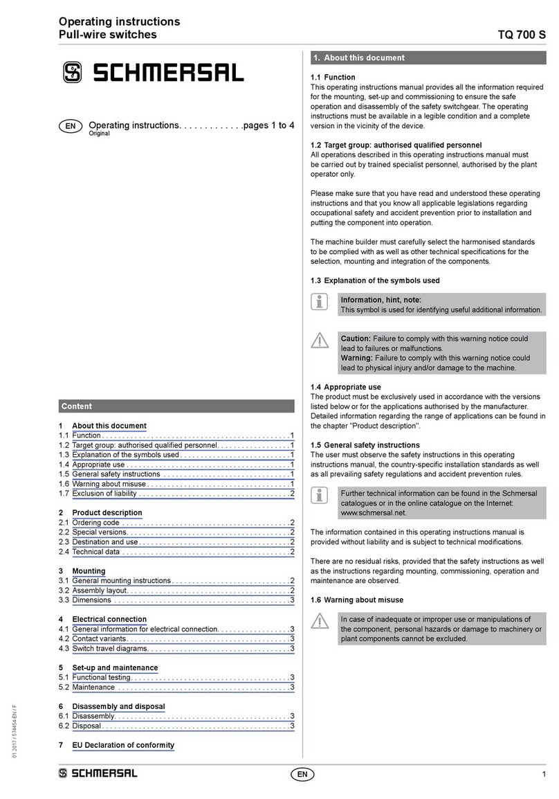
schmersal
schmersal TQ 700 S User manual
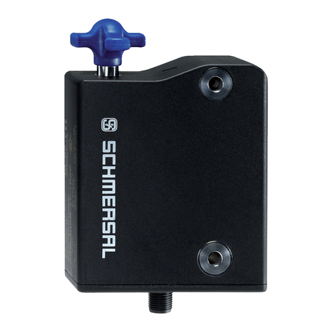
schmersal
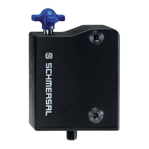
schmersal AZM300B-I2-ST-1P2P-A-DU User manual
schmersal
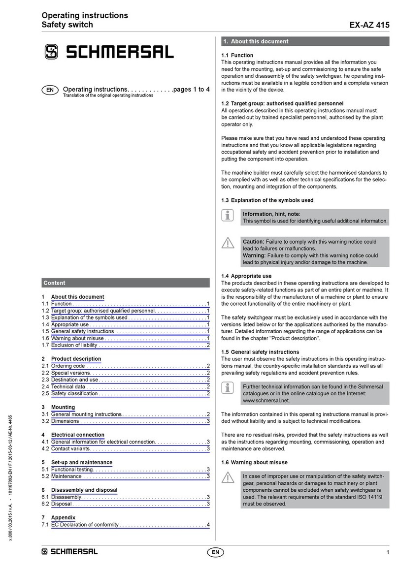
schmersal AZM300B-I1-ST1P2P-A User manual
schmersal
schmersal EX-AZ 415 User manual

schmersal
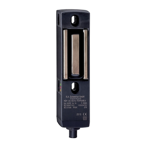
schmersal EX-ZQ 900 User manual
schmersal
schmersal MZM 120 User manual

schmersal
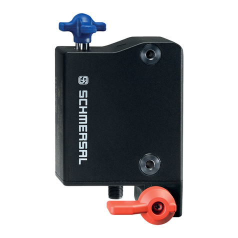
schmersal T 335 AS User manual
schmersal
schmersal AZM300B-ST-1P2P-T User manual
schmersal
schmersal EX-AZ 3350 Series User manual

schmersal
schmersal ZSD5 User manual
schmersal
schmersal TZG User manual
schmersal
schmersal AZM400Z-ST-I2-1P2P-BOW User manual
Popular Switch manuals by other brands

SMC Networks
SMC Networks SMC6224M Technical specifications

Aeotec
Aeotec ZWA003-S operating manual

TRENDnet
TRENDnet TK-209i Quick installation guide

Planet
Planet FGSW-2022VHP user manual

Avocent
Avocent AutoView 2000 AV2000BC AV2000BC Installer/user guide

Moxa Technologies
Moxa Technologies PT-7728 Series user manual

Intos Electronic
Intos Electronic inLine 35392I operating instructions

Cisco
Cisco Catalyst 3560-X-24T Technical specifications

Asante
Asante IntraCore IC3648 Specifications

Siemens
Siemens SIRIUS 3SE7310-1AE Series Original operating instructions

Edge-Core
Edge-Core DCS520 quick start guide

RGBLE
RGBLE S00203 user manual
