manuals.online logo
Brands
  1. Home
  2. •
  3. Brands
  4. •
  5. schmersal
  6. •
  7. Switch
  8. •
  9. schmersal TQ 700 User manual

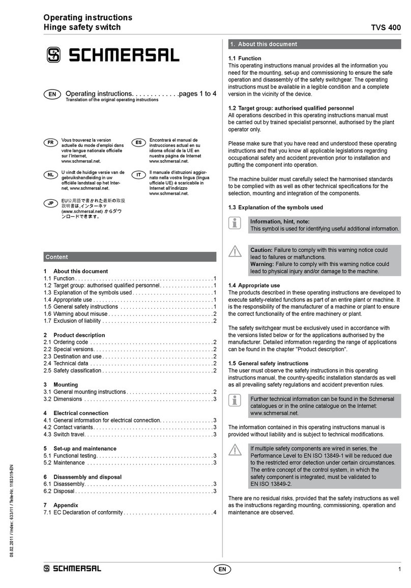
schmersal TQ 700 User manual

1
TQ 700
Operating instructions
Pull-wire switches
EN
1. About this document
1.1 Function
This operating instructions manual provides all the information required
for the mounting, set-up and commissioning to ensure the safe opera-
tion and disassembly of the safety switchgear. The operating instruc-
tions must be available in a legible condition and a complete version in
the vicinity of the device.
1.2 Target group: authorised qualified personnel
All operations described in this operating instructions manual must
be carried out by trained specialist personnel, authorised by the plant
operator only.
Please make sure that you have read and understood these operating
instructions and that you know all applicable legislations regarding
occupational safety and accident prevention prior to installation and
putting the component into operation.
The machine builder must carefully select the harmonised standards
to be complied with as well as other technical specifications for the
selection, mounting and integration of the components.
1.3 Explanation of the symbols used
Information, hint, note:
This symbol is used for identifying useful additional information.
Caution: Failure to comply with this warning notice could
lead to failures or malfunctions.
Warning: Failure to comply with this warning notice could
lead to physical injury and/or damage to the machine.
1.4 Appropriate use
The product must be exclusively used in accordance with the versions
listed below or for the applications authorised by the manufacturer.
Detailed information regarding the range of applications can be found in
the chapter "Product description".
1.5 General safety instructions
The user must observe the safety instructions in this operating instruc-
tions manual, the country-specific installation standards as well as all
prevailing safety regulations and accident prevention rules.
Further technical information can be found in the Schmersal
catalogues or in the online catalogue on the Internet:
www.schmersal.net.
The information contained in this operating instructions manual is
provided without liability and is subject to technical modifications.
There are no residual risks, provided that the safety instructions as well
as the instructions regarding mounting, commissioning, operation and
maintenance are observed.
1.6 Warning about misuse
In case of inadequate or improper use or manipulations of
the component, personal hazards or damage to machinery
or plant components cannot be excluded.
1.7 Exclusion of liability
We shall accept no liability for damages and malfunctions resulting from
defective mounting or failure to comply with this operating instructions
manual. The manufacturer shall accept no liability for damages result-
ing from the use of unauthorised spare parts or accessories.
Content
1 About this document
1.1 Function ..............................................1
1.2 Target group: authorised qualied personnel..................1
1.3 Explanation of the symbols used ...........................1
1.4 Appropriate use ........................................1
1.5 General safety instructions ...............................1
1.6 Warning about misuse ...................................1
1.7 Exclusion of liability .....................................1
2 Product description
2.1 Ordering code .........................................2
2.2 Special versions........................................2
2.3 Destination and use .....................................2
2.4 Technical data .........................................2
3 Mounting
3.1 General mounting instructions .............................2
3.2 Dimensions ...........................................2
3.3 Mounting set-up ........................................2
4 Electrical connection
4.1 General information for electrical connection..................3
4.2 Contact variants........................................3
5 Set-up and maintenance
5.1 Functional testing.......................................3
5.2 Maintenance ..........................................3
6 Disassembly and disposal
6.1 Disassembly...........................................3
6.2 Disposal ..............................................3
7 Appendix
7.1 EC Declaration of conformity ..............................4
573770 / 11.2015-EN
EN Operating instructions. . . . . . . . . . . . .pages 1 to 4
Translation of the original operating instructions
2
Operating instructions
Pull-wire switches TQ 700
EN
For safety reasons, invasive work on the device as well as arbitrary re-
pairs, conversions and modifications to the device are strictly forbidden;
the manufacturer shall accept no liability for damages resulting from
such invasive work, arbitrary repairs, conversions and/or modifications
to the device.
2. Product description
2.1 Ordering code
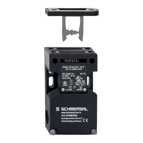
This operating instructions manual applies to the following types:
TQ 700-
➀
No. Option Description
➀
11 1 NO/1 NC contact
02 2 NC contacts
20 2 NO contacts
2.2 Special versions
For special versions, which are not listed in the order code below 2.1,
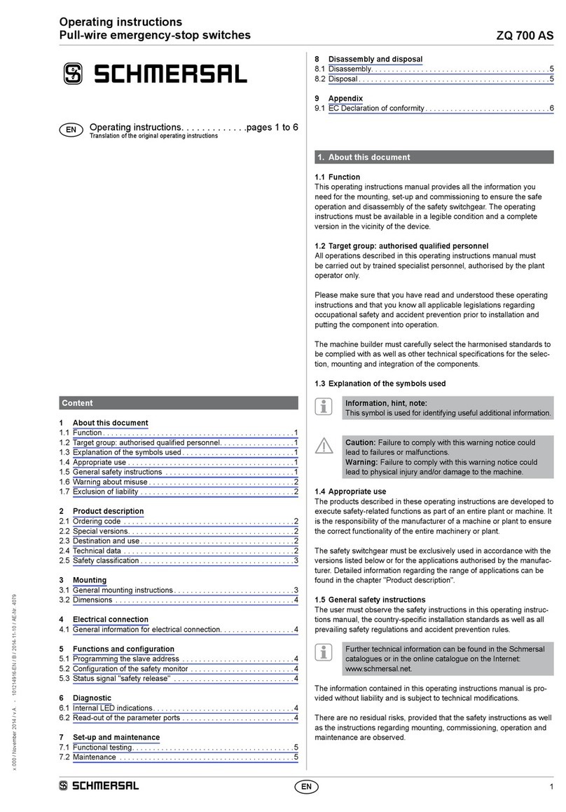
these specifications apply accordingly, provided that they correspond to
the standard version.
2.3 Destination and use
Pull-wire switches are used on machinery and plants, where triggering
the switching command must be enabled at arbitrary points on the wire
run. If the tensioned pull-wire is pulled or in case of wire breakage, the
switching function of the pull-wire switch is activated. (refer to image 1).
F
1
0
0
Image 1: position indication and actuation
Design/operating principle
The pull-wire switches are brought into the operational condition by
the proper pre-tensioning of a maximum 10 m long wire. The inner
switching element has 2 contacts; in a tensioned condition, the NC
contacts are closed and the NO contacts are open.
The pull-wire switch does not meet the requirements of ISO 13850,
IEC 60947-5-5 and NBR 13930.
2.4 Technical data
Standards: IEC 60947-5-1
Enclosure: thermoplastic
Cover: thermoplastic
Protection class: IP67 to IEC 60529
Contact material: Silver
Switching system: slow action with double break,
NC contact with positive break
A
Connection: screw terminals
Cable section: max. 2.5 mm²
(incl. conductor ferrules)
Cable entry: 1 x M20 x 1.5
Rated impulse withstand voltage Uimp:6 kV
Rated insulation voltage Ui:500 V
Thermal test current Ithe:10 A
Rated operating current/voltage Ie/Ue:4 A / 230 VAC,
4 A / 24 VDC
Utilisation category: AC-15, DC-13
Required short-circuit current: 1000 A
Max. fuse rating: 6 A gG D-fuse (EN 60269-1)
Ambient temperature: –25 °C … +70 °C
Relative humidity: 30 … 95%,
no condensation,
no icing
Wire length: max. 10 m depending in relation to the
range of ambient temperature (see image 3)
Mechanical life: >1 million operations
AWG 14
Solid/Stranded
Max. torque: 7 in. lb.
Use copper conductors only.
3. Mounting
3.1 General mounting instructions
The installation may only be carried out by authorised personnel. The
pull-wire switch is fitted by means of four screws (distance of the drill
holes 30 mm or 60 mm).
The maximum perpendicular traction force to be exercised
on the wire in order to activate the emergency pull-wire
switch is 200 N, the maximum deflection is 400 mm.
3.2 Dimensions
All measurements in mm.
TQ 700
2
77,4
60
160
93,75
17
30,5
40,5
42,5
30
40,5
p/M5
M20x1,5
A
Key
APosition indication
3.3 Mounting set-up
For tensioned span lengths up to 10 m, intermediate wire supports
are required every 2 to 5 m. To avoid resonance vibrations in the wire
on machines with high vibrations, it is recommended to realise the
individual support length differently. Assembly: refer to image 2.
3
TQ 700
Operating instructions
Pull-wire switches
EN
64 23 6561
0,1 m
2-5 m
max. 10 m
46 32
A
B
9
823
0,1 m
2-5 m
max. 10 m
1827
A
B
3
9
Image 2: mounting of the components
Key
1 Pull-wire with red PVC sheath Ø 5 mm (steel core: Ø 3 mm)
2 Eyebolt
3 Nut
4 Wire clamp
5 Tensioner
6 Wire thimble
7 Shackle
8 Wire tensioner S900
A Position indication
The pull-wire must be fixed to the ring and then be pre-tensioned until
the position indication is in the central position (refer to image 1).
Due to the thermal expansion behaviour of the wire, the maximum
authorised wire length is determined by the ambient temperature range
(refer to image 3).
We recommend the use of the ACC-700-RZ173 tension spring to
reduce the effects of temperature variations.
-10-20-30
1
2
3
4
5
6
7
8
9
1
0
010203040506070
l [m]
T[°C]
0■
without tension spring
■
with tension spring
Image 3: temperature-dependent maximum wire length with or without
tension spring
As the thimbles are subject to deformation in case of wire pull, the wire
should be pulled several times after fitting. After that, the wire must be
re-tensioned (see image 4).
Image 4: deformation of the wire thimbles
In order to ensure an optimal operation safety and to save
time during fitting, we recommend using the wire rope and
the combined fixing and tensioning system from Schmersal.
Alternatively, wire thimbles and wire clamps can be used
in conjunction with a tensioner. In this case, the red PVC
sheet must be removed in the clamp area prior to installing
the wire rope.
4. Electrical connection
4.1 General information for electrical connection
The electrical connection may only be carried out by authorised
personnel in a de-energised condition.
1. Cover screws must be loosened
2. Dust shield cap remove
3. Cable glands M20 x 1.5 with an appropriate degree of protection
must be used
4. When wiring, please ensure that no cables are located within the
range of the lever system and the pushbutton
5. The inside of the switch must be imperatively cleaned (e.g. removal
of cable residues), considering that foreign bodies can affect the
switching behaviour
6. The cover screws must be tightened uniformly (tightening torque 0.5 Nm)
The switch with plastic enclosure is double insulated. The use of an
earth wire is not authorised.
Accessories cable gland:
Ordering code: 103006013
Authorised cable diameter: 6 - 12 mm
Tightening torque: 4.5 Nm
4.2 Contact variants
The symbols are shown for the switch in non-actuated condition.
TQ 700-11 TQ 700-02 TQ 700-20
14
13
22
21
12
11
22
21
14
13
24
23
Key
A
Positive break NC contact
5. Set-up and maintenance
5.1 Functional testing
The function of the component must be tested. The following conditions
must be previously checked and met:
1. Correct fixing of the pull-wire switch
2. Check the integrity of the cable entry and connections
3. Check the switch enclosure for damage
4. Check the functionality of the switch by actuating the wire
5. Check the cable tensioning by means of the position indicator
5.2 Maintenance
A regular visual inspection and functional test, including the following
steps, is recommended:
1. Check the wire tension through the wire position indication and check
the wire and the wire guides for damages and proper fitting
2. Check the functionality of the switch by actuating the wire
3. Check the cable entries and the wire connections
4. Remove particles of dust and soiling
Do not open the device when live.
Damaged or defective components must be replaced.
6. Disassembly and disposal
6.1 Disassembly
The switch must be disassembled in a de-energised condition only.
6.2 Disposal
The switch must be disposed of in an appropriate manner in
accordance with the national prescriptions and legislations.
4
Operating instructions
Pull-wire switches TQ 700
EN
TQ700-E-EN
7. Appendix
7.1 EC Declaration of conformity
Name of the component: TQ 700
Description of the component: Pull-wire switches
Harmonised EC-Directives: 2006/95/EG EC Low Voltage Directive
K.A. Schmersal GmbH & Co. KG
Möddinghofe 30, D - 42279 Wuppertal
Postfach 24 02 63, D - 42232 Wuppertal
Phone +49 - (0)2 02 - 64 74 - 0
Telefax: +49 - (0)2 02 - 64 74 - 1 00
E-Mail: [email protected]
Internet: http://www.schmersal.com
Production site:
ACE Schmersal
Eletroeletrônica Industrial Ltda.
Av. Brasil, nº 815
Jardim Esplanada – CEP: 18550-000, Boituva – SP
Brazil
Phone +55 - (0)15 - 32 63 - 9866
Fax +55 - (0)15 - 32 63 - 9890
E-Mail: [email protected]
Internet: http://www.schmersal.com.br
Place and date of issue: Boituva, November 24, 2015
Authorised signature
Marco Antonio De Dato
Head of Engineering and Design
EC Declaration of conformity
Translation
of the original Declaration of Conformity
ACE Schmersal
Eletroeletrônica Industrial Ltda.
Av. Brasil, nº 815
Vila Esplanada
CEP: 18550-000 Boituva – SP
Brazil
Internet: www.schmersal.com.br
We hereby certify that the hereafter described products both in their basic design and construction
conform to the applicable European Directives.

This manual suits for next models

1

Other schmersal Switch manuals

schmersal EX-T. 454 Series User manual

schmersal

schmersal EX-T. 454 Series User manual

schmersal Z/T 235 Programming manual

schmersal

schmersal Z/T 235 Programming manual

schmersal SHGV User manual

schmersal

schmersal SHGV User manual

schmersal AZM201Z-CC-T-1P2PW-2719-1 Service manual

schmersal

schmersal AZM201Z-CC-T-1P2PW-2719-1 Service manual

schmersal MZM 120 User manual

schmersal

schmersal MZM 120 User manual

schmersal AZM300B-ST-1P2P-N User manual

schmersal

schmersal AZM300B-ST-1P2P-N User manual

schmersal EX-AZM 170 User manual

schmersal

schmersal EX-AZM 170 User manual

schmersal TZG User manual

schmersal

schmersal TZG User manual

schmersal T 335 AS User manual

schmersal

schmersal T 335 AS User manual

schmersal AZM300B-ST-1P2P-A-DU User manual

schmersal

schmersal AZM300B-ST-1P2P-A-DU User manual

schmersal TESZ User manual

schmersal

schmersal TESZ User manual

schmersal AZ201CC-T-1P2P Operation and maintenance manual

schmersal

schmersal AZ201CC-T-1P2P Operation and maintenance manual

schmersal TQ 700 S User manual

schmersal

schmersal TQ 700 S User manual

schmersal AZM201Z-I2-CC-T-1P2PW-A Operation and maintenance manual

schmersal

schmersal AZM201Z-I2-CC-T-1P2PW-A Operation and maintenance manual

schmersal AZM300B-I2-ST-1P2P-A User manual

schmersal

schmersal AZM300B-I2-ST-1P2P-A User manual

schmersal AZM300Z-ST-SD2P-T-DU User manual

schmersal

schmersal AZM300Z-ST-SD2P-T-DU User manual

schmersal ZQ 700 AS User manual

schmersal

schmersal ZQ 700 AS User manual

schmersal TFH 232 AS User manual

schmersal

schmersal TFH 232 AS User manual

schmersal AZM201B-SK-T-1P2PW-A Operation and maintenance manual

schmersal

schmersal AZM201B-SK-T-1P2PW-A Operation and maintenance manual

schmersal AZ 415 Series User manual

schmersal

schmersal AZ 415 Series User manual

schmersal EX-AZ 415 User manual

schmersal

schmersal EX-AZ 415 User manual

schmersal EX-Z/T 235 User manual

schmersal

schmersal EX-Z/T 235 User manual

schmersal EX-AZ 16 User manual

schmersal

schmersal EX-AZ 16 User manual

schmersal EX-AZ 3350 Series User manual

schmersal

schmersal EX-AZ 3350 Series User manual

Popular Switch manuals by other brands

TP-Link JetStream TL-SL3452 reference guide

TP-Link

TP-Link JetStream TL-SL3452 reference guide

Siemens AP 420/3 IR Operating and mounting instructions

Siemens

Siemens AP 420/3 IR Operating and mounting instructions

Belkin OMNIVIEW F1DN102D Quick installation guide

Belkin

Belkin OMNIVIEW F1DN102D Quick installation guide

Philips SWV3570 Specifications

Philips

Philips SWV3570 Specifications

ZooZ ZEN71 800LR user manual

ZooZ

ZooZ ZEN71 800LR user manual

Lindy No. 39123 user manual

Lindy

Lindy No. 39123 user manual

SMC Networks SMC8126L2 Management guide

SMC Networks

SMC Networks SMC8126L2 Management guide

Milestone pro MP-SUH4ARC-4K user manual

Milestone pro

Milestone pro MP-SUH4ARC-4K user manual

LevelOne GEP-0823 Quick installation guide

LevelOne

LevelOne GEP-0823 Quick installation guide

Fracarro SWP508TS operating instructions
Fracarro

Fracarro SWP508TS operating instructions
Belkin F5U231 user manual

Belkin

Belkin F5U231 user manual

StarTech.com 8STSV431HDU3A2 manual

StarTech.com

StarTech.com 8STSV431HDU3A2 manual

Barksdale BLS3000 operating instructions
Barksdale

Barksdale BLS3000 operating instructions

Transition Networks SISTM10xx-162-LR(T) installation manual

Transition Networks

Transition Networks SISTM10xx-162-LR(T) installation manual

Sun Microsystems Datacenter Switch 3456 installation guide

Sun Microsystems

Sun Microsystems Datacenter Switch 3456 installation guide

Planet IKVM-1000 user guide

Planet

Planet IKVM-1000 user guide

OPTIKVMMAX AS-K0004PS Specification sheet

OPTIKVMMAX

OPTIKVMMAX AS-K0004PS Specification sheet

NETGEAR GS716T - ProSafe Switch Specifications
NETGEAR

NETGEAR GS716T - ProSafe Switch Specifications
manuals.online logo
manuals.online logoBrands
  • About & Mission
  • Contact us
  • Privacy Policy
  • Terms and Conditions

Copyright 2025 Manuals.Online. All Rights Reserved.