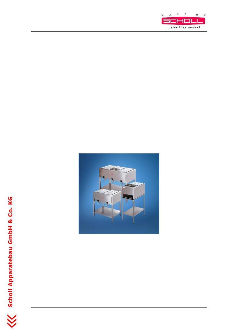
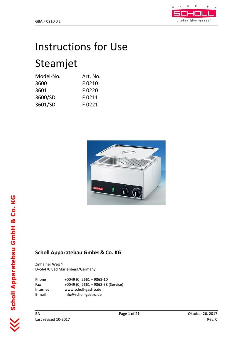
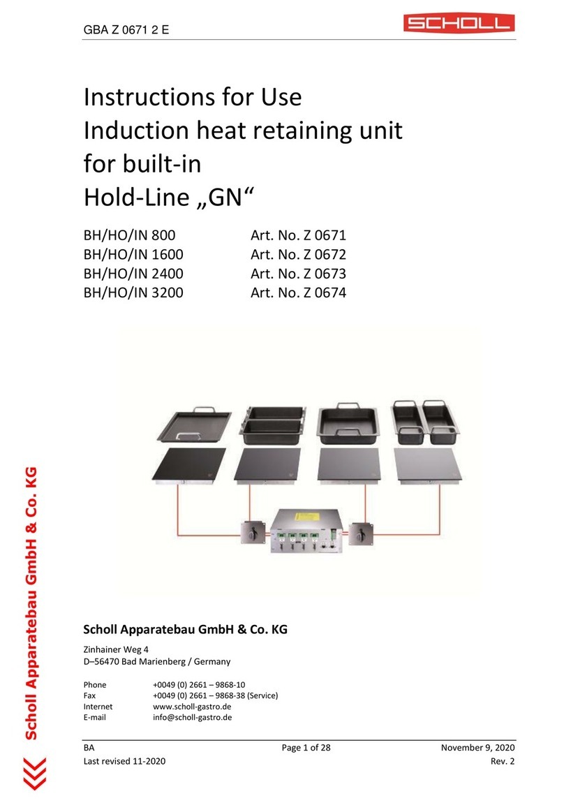
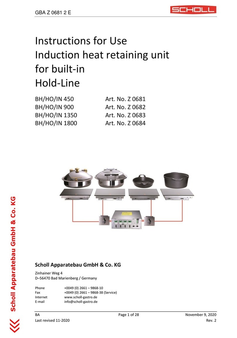
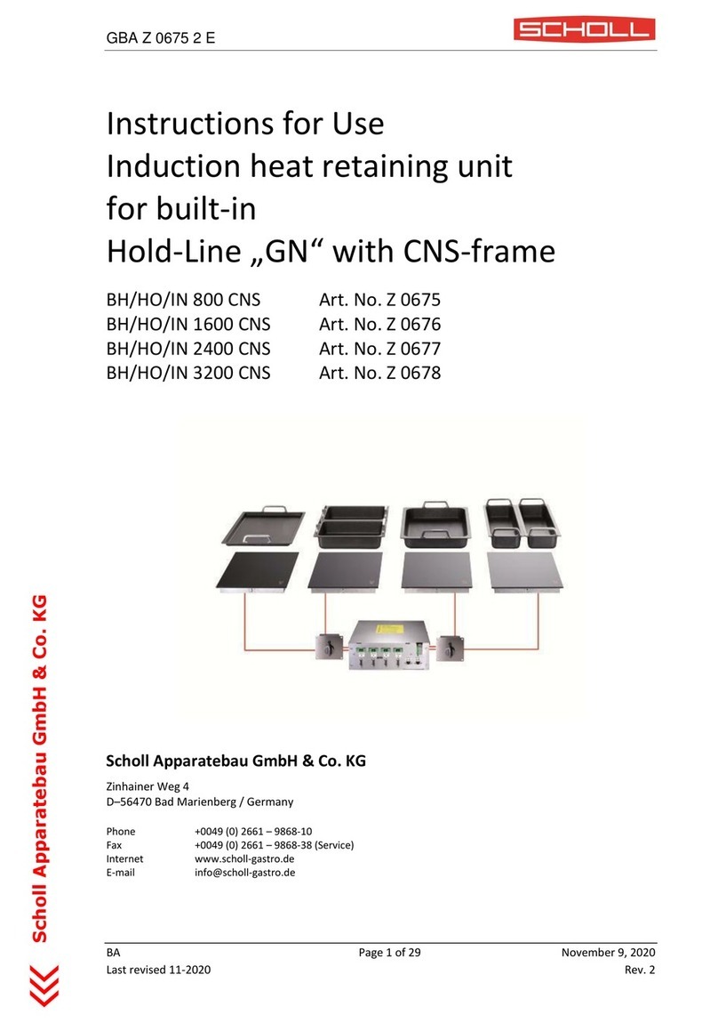
Scholl BH/HO/IN 450 CNS User manual

GBA Z 0697 2 E
BA Page 1 of 29 November 9, 2020
Last revised 11-2020 Rev. 2
Scholl Apparatebau GmbH & Co. KG
Instructions for Use
Induction heat retaining unit
for built-in
Hold-Line with CNS-frame
BH/HO/IN 450 CNS Art. Nr. Z 0697
BH/HO/IN 900 CNS Art. Nr. Z 0698
BH/HO/IN 1350 CNS Art. Nr. Z 0699
BH/HO/IN 1800 CNS Art. Nr. Z 0700
Scholl Apparatebau GmbH & Co. KG
Zinhainer Weg 4
D–56470 Bad Marienberg / Germany
Phone +0049 (0) 2661 –9868-10
Fax +0049 (0) 2661 –9868-38 (Service)
Internet www.scholl-gastro.de

GBA Z 0697 2 E
BA Page 2 of 29 November 9, 2020
Last revised 11-2020 Rev. 2
Scholl Apparatebau GmbH & Co. KG
TABLE OF CONTENTS
Table of contents............................................................................................................................................... 2
Preface............................................................................................................................................................... 4
1General remarks ........................................................................................................................................ 5
1.1 Description of danger signs.............................................................................................................. 5
1.2 Purpose of induction cookers .......................................................................................................... 6
1.2.1 Generall information on holding vessel....................................................................................... 6
2Description of products ............................................................................................................................. 7
2.1 Scope of supply ................................................................................................................................ 7
2.2 Product............................................................................................................................................. 7
2.3 Technical specifications ................................................................................................................... 8
3Installation................................................................................................................................................. 9
3.1 Scope of delivery.............................................................................................................................. 9
3.2 Requirements of installation............................................................................................................ 9
3.3 Definition of interfaces .................................................................................................................... 9
3.4 Installation clipping........................................................................................................................ 10
3.4.1 Installation clipping model BH/HO/IN 450 CNS......................................................................... 10
3.4.2 Installation clipping model BH/HO/IN 1800 CNS....................................................................... 11
3.5 Generator RTCSmp HO/IN 1800 .................................................................................................... 12
3.6 Mounting variations....................................................................................................................... 13
3.7 Cut-out Operation unit with potentiometer.................................................................................. 14
3.8 Electrical installation...................................................................................................................... 15
4Operation test ......................................................................................................................................... 16
5Operation ................................................................................................................................................ 17
5.1 Comfort.......................................................................................................................................... 17
6Safety instructions................................................................................................................................... 18
6.1 Risk in the event of non-observance of the safety information .................................................... 18

GBA Z 0697 2 E
BA Page 3 of 29 November 9, 2020
Last revised 11-2020 Rev. 2
Scholl Apparatebau GmbH & Co. KG
6.2 Safety conscious work.................................................................................................................... 18
6.3 Safety information for the operator/operating personnel ............................................................ 18
6.4 Unauthorized reconstruction and use of spare parts .................................................................... 19
6.5 Improper operating methods ........................................................................................................ 19
6.6 Pan detection................................................................................................................................. 19
6.7 Temperature regulation................................................................................................................. 19
7Out of operation...................................................................................................................................... 20
8Fault finding/Rectification ....................................................................................................................... 21
8.1 Fault finding with error code ......................................................................................................... 22
8.2 Fault finding without error code.................................................................................................... 23
9Cleaning ................................................................................................................................................... 25
10 Support............................................................................................................................................... 26
11 Waste disposal concept...................................................................................................................... 27
11.1 Avoid abuse.................................................................................................................................... 27
12 Warranty and service ......................................................................................................................... 28
12.1 Warranty conditions ...................................................................................................................... 28
12.2 Service............................................................................................................................................ 28
12.3 Service address .............................................................................................................................. 29

GBA Z 0697 2 E
BA Page 4 of 29 November 9, 2020
Last revised 11-2020 Rev. 2
Scholl Apparatebau GmbH & Co. KG
PREFACE
Congratulations!
In purchasing this new SCHOLL appliance you have chosen a product which meets highest technical stand-
ards while providing outstanding convenience in practical use.
This appliance has been designed with minimal energy consumption in mind. Used responsibly, it will serve
you well in an ecologically sound manner.
Please read the information in this manual carefully before starting up this appliance. On the following
pages you will find important notes regarding its operation, care and maintenance so that you will be able
to enjoy its use for a long time.
If a malfunction should nevertheless occur, please consult the "Troubleshooting" section first. In many cases
you should be able to remedy minor problems yourself, thus saving unnecessary service costs.
Please retain this manual carefully and pass it on to any subsequent user for his or her information and
safety.
A quality product, properly treated, will give you many years of satisfactory service.
We trust you will enjoy using this product!
Yours sincerely
Gustav Scholl Apparatebau GmbH & Co. KG

GBA Z 0697 2 E
BA Page 5 of 29 November 9, 2020
Last revised 11-2020 Rev. 2
Scholl Apparatebau GmbH & Co. KG
1 GENERAL REMARKS
These instructions for use contain information which is fundamentally important and must be taken into
account during assembly, operation and maintenance. They must therefore be read very carefully before
installation and operation by the responsible specialist staff and the operator(s). They must always be avail-
able for consultation at the place of operation.
1.1 DESCRIPTION OF DANGER SIGNS
General hazard symbol:
Non-observance of the safety regulations signifies a
hazard (injuries).
Electrical voltage:
This symbol warns of electric voltage.
CAUTION
Indicates a hazard or unsafe practice which could
result in minor personal injury or property damage.
Electromagnetic field
To reduce the risk of fire or electric shock,
do not remove or open cover.
No user serviceable parts inside.
Refer servicing to qualified personnel.
Hazard symbols attached directly to the unit must always be taken into account and the visibility must al-
ways be assured.
Warning!
Risk of fire or electric shock!
Do not open!

GBA Z 0697 2 E
BA Page 6 of 29 November 9, 2020
Last revised 11-2020 Rev. 2
Scholl Apparatebau GmbH & Co. KG
1.2 PURPOSE OF INDUCTION COOKERS
The induction heat retaining units „RTCS Install Hold-Line“ are especially made to keep food warm, as built-
in units, installed in closed counters. The heat retaining process with this „RTCS Install Hold-Line“ unit is
adjusted to induction Chafing Dish or to induction suitable pans (minimal bottom diameter is 20 cm).
Make sure that the Chafing Dish is put in the center of the ceran surface. For holding liquid, it is required to
use a lid. For an amount of more than 4 litres it is recommended to use another high capacity unit.
1.2.1 GENERALL INFORMATION ON HOLDING VESSEL
Vessel bottom must be ferritic, with a minimal thickness of 2mm and a minimal diameter of 20cm.
The bottom shouldn’t be bigger than the ceran glass, to avoid an overheated display.
If a ceramic vessel is used, a ferritic coating on vessels bottom is required.
The vessel must havea direct contact to the glass. Bottom must be flat without any structure.
When using open containers, we recommend the additional use of heat lamps to ensure the top heat.
When using inappropriate vessels, performance and function may be adversely affected.

GBA Z 0697 2 E
BA Page 7 of 29 November 9, 2020
Last revised 11-2020 Rev. 2
Scholl Apparatebau GmbH & Co. KG
2 DESCRIPTION OF PRODUCTS
2.1 SCOPE OF SUPPLY
•Generator
•1-2 control units
(1 heat retaining plate with 1 controller /
2-4 heat retaining plates 2 controller)
•One to four heat retaining plates
2.2 PRODUCT
There is one model with four connectivity options available. Built in a robust method of construction, they
are compact and powerful with a revolutionary technology. According to requirements, one to four built-in
frames can be connected. The temperature range of 50-100°C // 122°F-212°F give flexibility and allow a
perfect food temperature adjustment.
•Simple built-in solution thanks to its frame design
•Compact module with an induction generator, coil with ceramic glass surface and a control unit with
a 50-100°C // 122°F-212°F
•Simple operation with a rotary switch, the compact powerful electronic enable flat construction and
safe operation
•A maximum of safety thanks to multiple protections
•Electronical limitation of power
•Compact measurement –light weight
Fulfills the latest standards:
EN 60335-1/-2-36, EN 62233
EN 60335-2-49; EN 55011
EN 61000
CE-conform
ANSI/UL 197; CSA C 22.2 No.109
FCC Part 18; ICES-001
NSF/ANSI 4

GBA Z 0697 2 E
BA Page 8 of 29 November 9, 2020
Last revised 11-2020 Rev. 2
Scholl Apparatebau GmbH & Co. KG
2.3 TECHNICAL SPECIFICATIONS
Type
Case of
generator
Ceran surface
Heat reten-
tion plate
CNS-frame
Cut-out for
CNS-frame
BH/HO/IN
303x312x135
mm
322x322x4
mm
322x322x75
mm
390x390x24
mm
360x360 mm
Type
Voltage
Power
Heat retention
fields
temperature
operation units
BH/HO/IN 450
230V
0,45kW
1
1
BH/HO/IN 900
230V
0,90kW
2
2
BH/HO/IN 1350
230V
1,35kW
3
2
BH/HO/IN 1800
230V
1,80kW
4
2
Operating conditions
Max. tolerance of supply voltage +6%/-10%
Supply frequency 50/60Hz
Protection class IP X0
Min. diameter oft he pan 20cm
Max. ambient temperature
Storage -20°C - +70°C
Function +5°C - +40°C
Max. relative humidity of air
Storage 10% - 90%
Function 30% - 90%

GBA Z 0697 2 E
BA Page 9 of 29 November 9, 2020
Last revised 11-2020 Rev. 2
Scholl Apparatebau GmbH & Co. KG
3 INSTALLATION
3.1 SCOPE OF DELIVERY
The generator is delivered with one to four built-in heat retention plates including glass tops and CNS-
frames and one to two operating units (with 1 heat retention plate 1 temperature operation unit –with 2 –
4 heat retention plates 2 temperature operation units).
CAUTION
Please note that the unit is not completely assem-
bled. Pay attention to the requirements of installa-
tion.
3.2 REQUIREMENTS OF INSTALLATION
The heat retention plate must be mounted on an even place like a table or counter which must be able to
withstand a loading of 40kg. The thickness of the top plate must not exceed 25mm. The generator can as an
example be fixed in a closed drawer with doors. Air inlet and air outlet must not be obstructed. The control
knob to operate the unit must be easily accessible.
RTCSmp Install Hold-Line units must only be fixed in closed counters.
The rear side of the induction unit below the fan (air intake) has to be absolutely free regarding to danger of
obstruction. An optimal air intake must not be reduced by the installation. The max air flow is 96m3/h and
therefore a minimal opening of 6000 mm2has to be maintained. If necessary, a perfect air supply has to be
guaranteed by adding a flexible air duct including a shackle (available as accessory). Pay special attention to
the air inlet and air outlet openings: there has to be a distance of at least 40mm between obstructions like
walls or floors. In addition to that, pay attention that the exhausted air is not recirculated together with the
fresh air. We recommend guaranteeing a supply of fresh air by fixing an air duct incl. shackle or by air open-
ings. The air exit must not to be hindered by any obstructions.
3.3 DEFINITION OF INTERFACES
Please observe the following rules:
•Check and ensure that the supply voltage and the line current matches the specifications given on
the rating plate.
When residual current circuit breakers are used, it has to be taken into account, that by switching on
an induction generator to a power supply system, leakage current can be caused for a short period
due to the asymmetry. This leakage current can activate the residual current circuit breakers. While
the choosing residual current circuit breakers, please note that the generator generates direct as
well as alternating current in high frequency areas of approx. 20 kHz. Our recommendation is to
choose a residual current circuit breaker suitable for these requirements. If the residual current cir-
cuit breakers are used as protection for People, the breakers must be in compliance to the specific
National and local regulations for personal security.
The minimal distance between the heat retaining plates is 10cm.
Connection A must be always connected.
•This induction unit is equipped with an internal air cooling system. Make sure that the air supply and
air exhaust are not blocked (wall, fabric etc.).
GBA Z 0697 2 E
BA Page 10 of 29 November 9, 2020
Last revised 11-2020 Rev. 2
Scholl Apparatebau GmbH & Co. KG
•Make sure that the induction unit does not take in hot ambient air (concerns units standing side by
side, or one behind the other, or standing near a frying pan or an oven), otherwise an air duct incl.
shackle has to be added.
•The induction unit must not be placed next to an oven or another heat producing unit.
•The air intake temperature must not exceed 40°C.
•The operating staff has to make sure that installation, support and inspection is done by qualified
personnel.
3.4 INSTALLATION CLIPPING
3.4.1 INSTALLATION CLIPPING MODEL BH/HO/IN 450 CNS
Cut-out CNS-frame in top plate: 360 x 360 mm
Advice for installation heat retention plate:
As soon as the mounting devices according to the above-mentioned steps are finished, you may continue
with installation. Put the heat retention plate with coil and ceran surface into the clipping. Install the
mounting construction on the working area and seal it with Pactan. The connecting cables have a length of
2.5m. The connecting cable must be laid and must not be rolled up.

GBA Z 0697 2 E
BA Page 11 of 29 November 9, 2020
Last revised 11-2020 Rev. 2
Scholl Apparatebau GmbH & Co. KG
3.4.2 INSTALLATION CLIPPING MODEL BH/HO/IN 1800 CNS
Cut-out CNS-frame in top plate: 360 x 360 mm
Advice for installation heat retention plate:
As soon as the mounting devices according to the above-mentioned steps are finished, you may continue
with installation. Put the heat retention plate with coil and ceran surface into the clipping. Install the
mounting construction on the working area and seal it with Pactan. The connecting cables have a length of
2.5m. The connecting cable must be laid and must not be rolled up.

GBA Z 0697 2 E
BA Page 12 of 29 November 9, 2020
Last revised 11-2020 Rev. 2
Scholl Apparatebau GmbH & Co. KG
3.5 GENERATOR RTCSMP HO/IN 1800
Advice for installation generator:
The rear case of the generator is equipped with two holes for the installation. Make sure that the height
distance between fan and bottom and the laterial openings for air exit have a distance to obstacles of at
least 40mm.

GBA Z 0697 2 E
BA Page 13 of 29 November 9, 2020
Last revised 11-2020 Rev. 2
Scholl Apparatebau GmbH & Co. KG
3.6 MOUNTING VARIATIONS

GBA Z 0697 2 E
BA Page 14 of 29 November 9, 2020
Last revised 11-2020 Rev. 2
Scholl Apparatebau GmbH & Co. KG
3.7 CUT-OUT OPERATION UNIT WITH POTENTIOMETER
Advice for installation operation unit:
This unit is supplied completely with an operation unit. In order to fix this on a cover, take the clipping for
the power switch into account. The operation control panel has to be fixed vertically on the installation
panel. The cable for the power switch has a length of 300cm.

GBA Z 0697 2 E
BA Page 15 of 29 November 9, 2020
Last revised 11-2020 Rev. 2
Scholl Apparatebau GmbH & Co. KG
3.8 ELECTRICAL INSTALLATION
CAUTION
If the voltage is wrong, the induction unit can be
damaged.
The installation of the electricity must be fitted by approved installation contractors in accordance with
specific national and local installation in conformity with all safety regulations. The warning signs and rating
plates on the units must strictly be followed.
Check and ensure that the supply voltage and the line current match the specifications given on the rating
plate.
Max. tolerance of supply voltage +6/-10%
Supply frequency 50/60Hz
•Turn control knob to OFF-position („ “)
•Connect operating unit to the generator
•Connect the coil cables to the plugs fixed at the front of the case
•Connect each built-in frame to earth at the respective bolts
•Connect the unit to the power socket
The installation is now finished and an operating test must be done according to chapter “operation test”.

GBA Z 0697 2 E
BA Page 16 of 29 November 9, 2020
Last revised 11-2020 Rev. 2
Scholl Apparatebau GmbH & Co. KG
4 OPERATION TEST
CAUTION
The glass ceramic zone is warmed up from the heat
of the serving pan. To avoid injuries (burning) do not
touch this area.
Use exclusively the Induction-Chafing Dish suitable for the RTCSmp Install Hold-Line heat retention units or
Pan that is suitable for induction unit, having a bottom diameter of at least 20 cm.
•Put some water in the serving pan and place it in the center of the heating area.
•Turn the control knob to an ON-position, temperature between 50-100°C. The 7-Segment display
underneath the ceran glass shows the choosen temperature and the current temperature, the water
will be heated.
•Take the serving pan away from the heat retention area, power transmition stops.
•Place the serving pan back on the heat retention area, the heating retention process will continue.
•Turn the control knob in the OFF-position, the heat retention process will stop, if temperature is over
50°C, display shows HOT, otherwise it turns off.
The indication of the measured temperature means that energy is being transferred to the the bottom of
the Chafing Dish or the bottom of the Pan (cast-iron or multilayer).
If the display remains off, check the following:
•Is the induction unit connected to the mains supply?
•Is the control knob in ON positon?
•Do you use the suitable Chafing Dish or a Pan that is suitable for induction unit, having a bottom di-
ameter of at least 20 cm?
•Is the serving pan placed in the center of the heating area?
If in spite of all positive controls and tests, the induction unit does not work, refer to the Fault Finding Sec-
tion.

GBA Z 0697 2 E
BA Page 17 of 29 November 9, 2020
Last revised 11-2020 Rev. 2
Scholl Apparatebau GmbH & Co. KG
5 OPERATION
Heat retention process
The heat retention unit is immediately ready for operation. The shining display indicates that energy is
transferred to the bottom of the Chafing Dish or to the bottom of the Pan. The temperature rating is set by
turning the control knob.
Make sure to cover the pots or pans with a lid if fluids are kept warm.
Pots and pans must not be over 100°C when placed on the heat retention plate, this may lead to damages
of the glass, or to a safety cutoff.
5.1 COMFORT
The generator transmits energy only when a serving pan is placed on the heating area and a temperature is
chosen. If you take all bacs away from the heating area, the power transfer stops immediately. If they are
put back on the heating area, the power will be transferred again.
After switching the power switch to the OFF-position „ “, the heat retention process will stop. Heat is
only be stored in the pot or pan.

GBA Z 0697 2 E
BA Page 18 of 29 November 9, 2020
Last revised 11-2020 Rev. 2
Scholl Apparatebau GmbH & Co. KG
6 SAFETY INSTRUCTIONS
6.1 RISK IN THE EVENT OF NON-OBSERVANCE OF THE SAFETY INFORMATION
Danger for persons, for the environment and for the induction unit as well as claims for damages of any
kind can result of non-observance of the safety information. Certain risks may be associated with non-
observance of precautions, including:
•Danger to persons through electrical causes
•Danger to persons through overheated Chafing Dish (ATTENTION: without water) or
Pan (cast-iron or multilayer)
•Danger to persons through an overheated cooking platform (ceran plate)
6.2 SAFETY CONSCIOUS WORK
The safety information pointed out in these instructions for use, the existing national regulation for the
prevention of accidents as well as any internal working, operating and safety regulation stipulated by the
operator must be observed at any time.
6.3 SAFETY INFORMATION FOR THE OPERATOR/OPERATING PERSONNEL
Any risks from electric power must be eliminated. The heating area is warmed up from the heat of the bot-
tom of the Chafing Dish or the buttom of the Pan. To avoid injuries (burning) do not touch the heating area.
•Switch the control knob off if you take the Chafing Dish or Pan away for a while. This will avoid the
heating process to continue automatically when a serving pan is placed back on the heating area. So,
if a person starts to use the induction unit, he/she will have to start the heating process by turning
the control knob in the ON-position.
•Do not place any piece of paper, cardboard, cloth, etc. between the Chafing Dish and the heating ar-
ea or between the Pan and the heating area, as this might initiate a fire.
•As metallic objects are heated up very quickly when placed on the heating area, do not place any
other objects than the Chafing Dish or the Pan, (closed cans, aluminium foil, cutlery, jewelry, watch-
es etc.) on the heat retention field.
•Persons with a cardiac pacemaker should consult their doctor whether they are safe near an induc-
tion unit.
•Aluminium foil and plastic vessels must not be placed on the hot surface.
•The surface must not be used for storage.
•Do not place credit cards, phone cards, cassette tapes, or other objects sensitive to magnetism on
the ceran plate.
•The induction heat retention unit has an internal air-cooling system. Do not obstruct the air inlet-
and air outlet-slots with objects (cloth). This would cause overheating and therefore the unit would
switch off.
•Avoid liquid entering into the induction unit. Do not let water or food overflow the bac. Do not clean
the induction unit with a jet of water.
•If the heating area (ceran plate) is cracked or broken, the induction unit must be switched off and
disconnected from the electric connection. Do not touch any parts inside the unit.

GBA Z 0697 2 E
BA Page 19 of 29 November 9, 2020
Last revised 11-2020 Rev. 2
Scholl Apparatebau GmbH & Co. KG
•If the supply cord is damaged, it must be replaced by the manufacturer, the service agent or a simi-
larly qualified person in order to avoid a hazard.
6.4 UNAUTHORIZED RECONSTRUCTION AND USE OF SPARE PARTS
Reconstruction of the induction unit or changes to the induction unit is not allowed. Contact the manufac-
turer if you intend to make any changes. To guarantee safety, just use genuine spare parts and accessories
authorized by the manufacturer. The use of other components will void all warranty.
6.5 IMPROPER OPERATING METHODS
The operating reliability of the induction unit can only be guaranteed by careful use. The limit values may
not be exceeded on any account.
6.6 PAN DETECTION
Pans having a diameter less than 20cm are not detected. No power is transferred if no Chafing Dish or an
unsuitable serving pan is detected.
6.7 TEMPERATURE REGULATION
The desired temperature is set by turning the rotary switch on the operation unit. Any temperature be-
tween 50 and 100°C can be chosen.

GBA Z 0697 2 E
BA Page 20 of 29 November 9, 2020
Last revised 11-2020 Rev. 2
Scholl Apparatebau GmbH & Co. KG
7 OUT OF OPERATION
If the induction unit is out of operation make sure that the control knob is in the OFF-position. If you do not
use the unit for a long period (several days), unplug the unit. Make sure that no liquid can enter into the
unit, do not clean the induction unit with a jet of water.
This manual suits for next models
7
Table of contents
Other Scholl Commercial Food Equipment manuals

Scholl
Scholl Steamjet 3600 User manual

Scholl
Scholl DR1335BEP Installation guide

Scholl
Scholl 3010 UA User manual

Scholl
Scholl 29000/S User manual

Scholl
Scholl BH/HO/IN 800 User manual

Scholl
Scholl BH/HO/IN 450 User manual

Scholl
Scholl 3111/ZAU User manual

Scholl
Scholl A 0811 User manual

Scholl
Scholl CK 330 User manual

Scholl
Scholl BH/HO/IN 800 CNS User manual