Scholl CK 330 User manual
Other Scholl Commercial Food Equipment manuals
Scholl
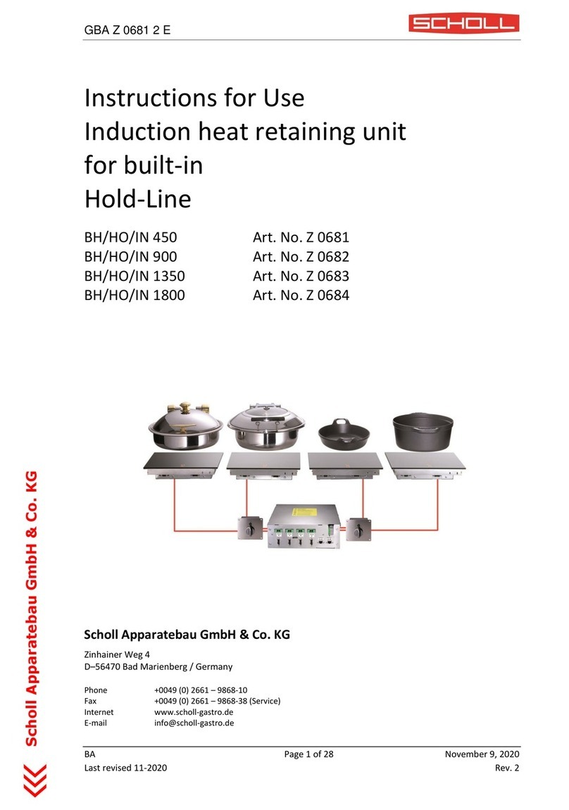
Scholl BH/HO/IN 450 User manual
Scholl
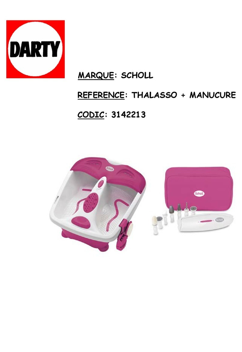
Scholl DR1335BEP Installation guide
Scholl
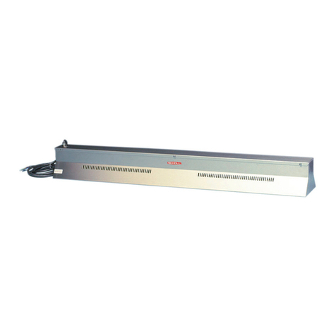
Scholl 29065/H User manual
Scholl
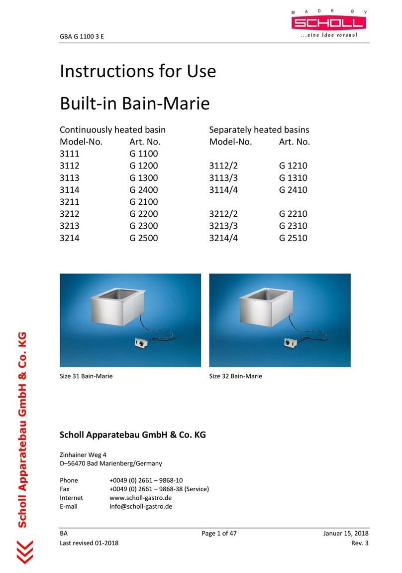
Scholl 3111 User manual
Scholl
Scholl 26060 Series User manual
Scholl
Scholl 3111/ZAU User manual
Scholl
Scholl BH/HO/IN 800 CNS User manual
Scholl
Scholl 3010 TA User manual

Scholl
Scholl ZAU/NIV User manual
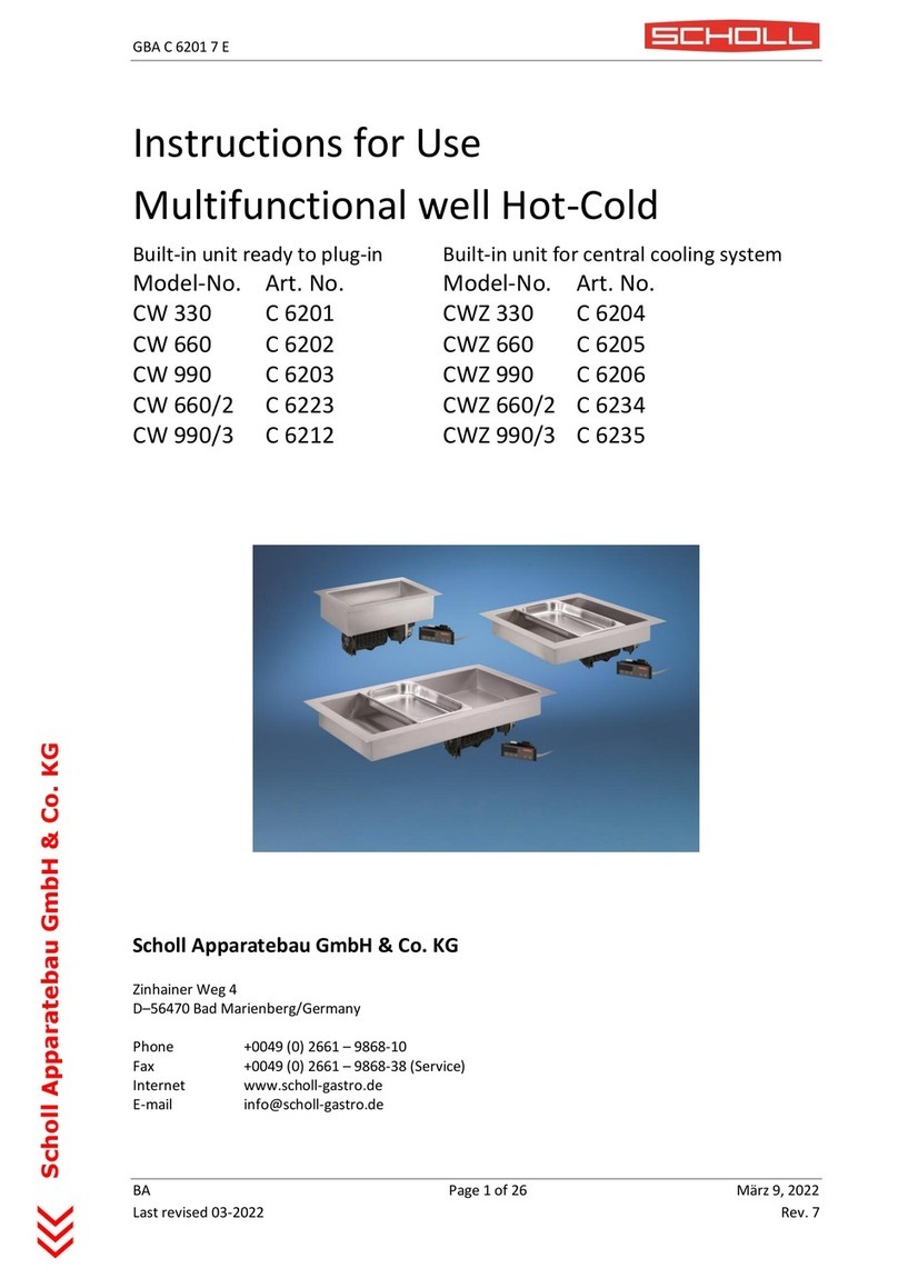
Scholl
Scholl CW 330 User manual
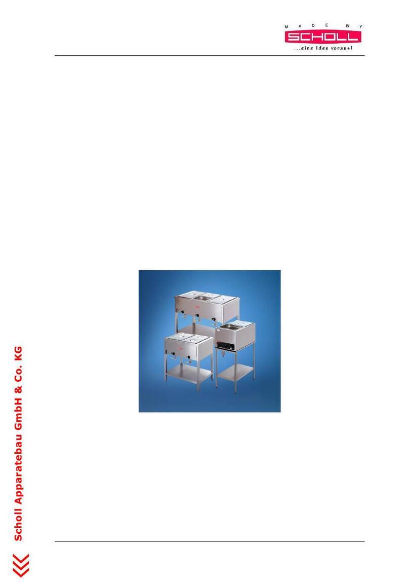
Scholl
Scholl 3010 UA User manual
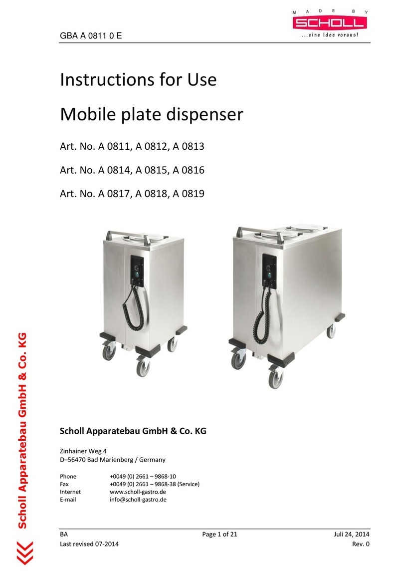
Scholl
Scholl A 0811 User manual
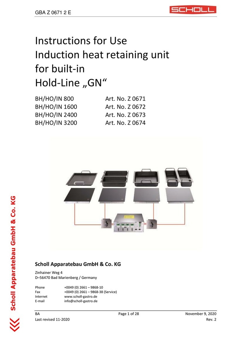
Scholl
Scholl BH/HO/IN 800 User manual
Scholl
Scholl Steamjet 3600 User manual
Scholl
Scholl 2009 User manual
Scholl
Scholl SH/BR 6000-ML User manual

Scholl
Scholl BH/HO/IN 450 CNS User manual
Scholl
Scholl 29000/S User manual
Scholl
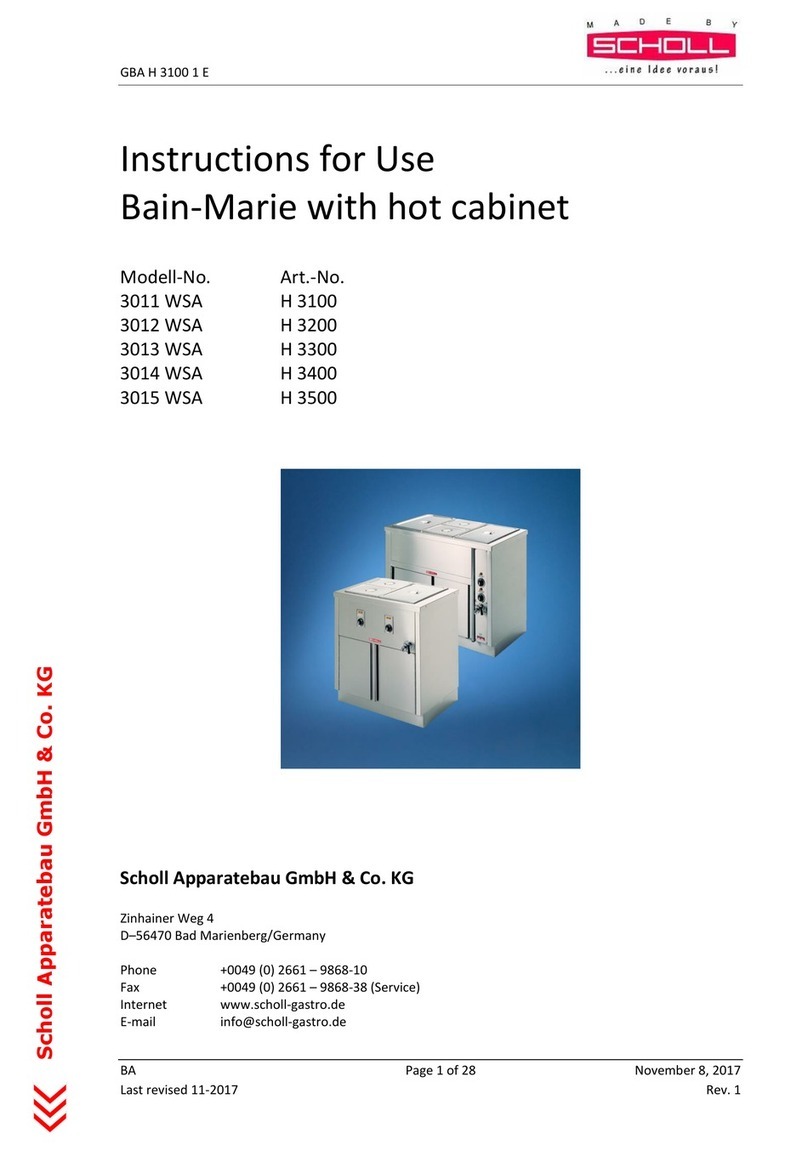
Scholl 3011 WSA User manual
Popular Commercial Food Equipment manuals by other brands

Diamond
Diamond AL1TB/H2-R2 Installation, Operating and Maintenance Instruction

Salva
Salva IVERPAN FC-18 User instructions

Allure
Allure Melanger JR6t Operator's manual

saro
saro FKT 935 operating instructions

Hussmann
Hussmann Rear Roll-in Dairy Installation & operation manual

Cornelius
Cornelius IDC PRO 255 Service manual

Moduline
Moduline HSH E Series Service manual

MINERVA OMEGA
MINERVA OMEGA DERBY 270 operating instructions

Diamond
Diamond OPTIMA 700 Installation, use and maintenance instructions

Diamond
Diamond G9/PLCA4 operating instructions

Cuppone
Cuppone BERNINI BRN 280 Installation

Arneg
Arneg Atlanta Direction for Installation and Use


