Schuchmann SOFIE User manual

Instructions for use.
soe. The versatile seat unit that grows with the child.
soe.


Our promise.
Dear Customer,
at this point we would like to thank you for placing your trust in our company and for
purchasing our product. We ask you to read through the Instructions for use carefully
prior to initial commissioning of the product, and to observe them. Please note that gui-
delines and representations in these Instructions for use may deviate from your product
due to diering equipment.
We reserve the right to make technical modifications.
Important information!
Ensure that these Instructions for use remain with the product..
Your schuchmann-Team

04 Contents.
1. Preparation. ...................................................................................05
1.1 Delivery....................................................................................................................... 05
1.2 Safety measures prior to use.......................................................................... 05
1.3 Safe disposal.......................................................................................................... 05
1.3.1 Packaging............................................................................................... 05
1.3.2 Product.................................................................................................... 05
1.4 Where to store the Instructions for use..................................................... 05
2. Product description. .......................................................................06
2.1 Material information............................................................................................ 06
2.2 Handling / transport.......................................................................................... 06
2.3 Anwendungsbereiche, bestimmungsgemäße Verwendung.......... 06
2.4 Use not in accordance with the intended
purpose / warning guidelines...............................................................................07
2.5 Equipment for basic model.............................................................................07
2.6 List of accessories ............................................................................................... 08
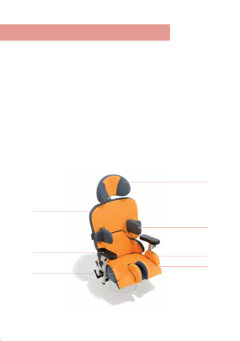
2.7 Product overview ................................................................................................. 08
3. Settings. ........................................................................................09
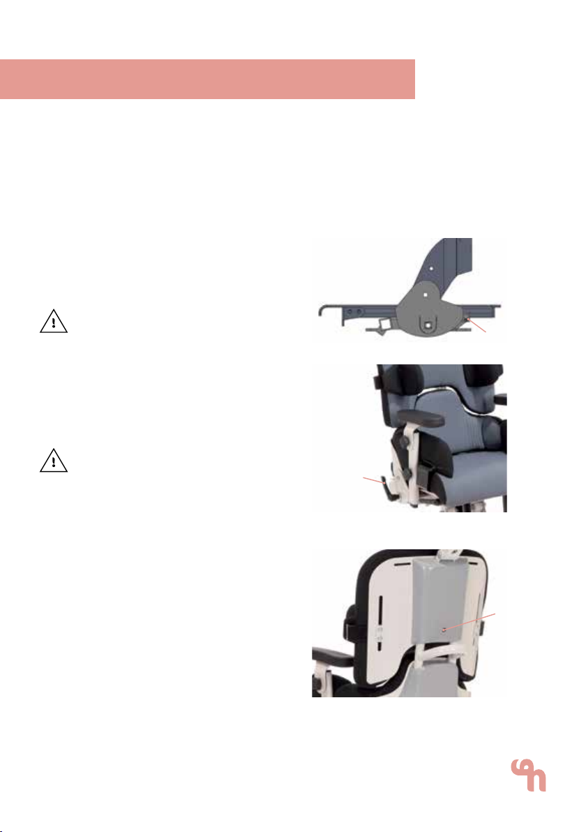
3.1 Seat depth .............................................................................................................. 09
3.2 Back inclination.................................................................................................... 09
3.3 Back height ............................................................................................................ 09
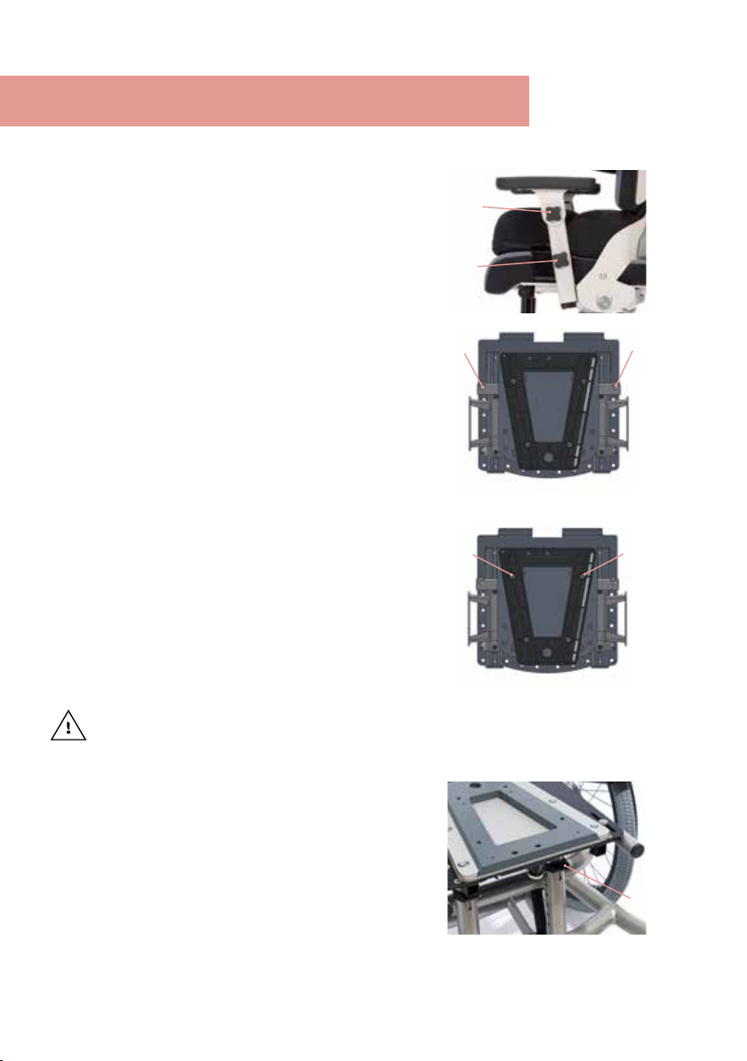
3.4 Armrests..................................................................................................................... 10
3.5 Adpater / Anpassung der Sitztiefe ............................................................. 10
3.6 Trapezoidal adapter........................................................................................... 10
4. Accessories. ...................................................................................11
4.1 Headrest......................................................................................................................11
4.2 Removable back ....................................................................................................11
4.3 Thorax pelotte pads.............................................................................................11
4.6 Abducting leg guides..........................................................................................13
4.8 Therapietisch...........................................................................................................14
4.9 Knee abduction wedge .....................................................................................14
4.10 Foot support..........................................................................................................15
4.11.1 Positioning of the footrests............................................................................ 17
4.12 Fußstützen mit Fußschalen..............................................................................18
5. Repairs and cleaning. .....................................................................19
5.1 Cleaning......................................................................................................................19
5.2 Repairs ........................................................................................................................19
5.3 Spare parts...............................................................................................................19
5.4 Duration of use and re-use..............................................................................19
6 . Technical data. ..............................................................................20
7. Guarantee. .....................................................................................20
8. Identication. ................................................................................21
8.1 EG-Konformitätserklärung.................................................................................21
8.2 Serial number / date of manufacture .......................................................22
8.3 Product version......................................................................................................22
8.4 Issue of the document.......................................................................................22
8.5 Name and address of the manufacturer,
specialist dealer supplying the product..........................................................22

05 1. Preparation.
1.1 Delivery
On receiving the product, please check it for completeness, lack of faults
and any transport damage. Inspect the goods in the presence of your for-
warder Should transport damage have occurred, please arrange for an
inventory (determination of the faults) to be made in the presence of the
forwarder. Please send a complaint in writing to the specialist dealer res-
ponsible (see point 8.5).
1.2 Safety measures prior to use
Correct usage of the seat unit requires precise and careful training of the
accompanying person. We ask you to read through the Instructions for use
carefully prior to initial commissioning of the seat unit, and to observe them.
Cushioned parts may become warm when exposed to direct sunlight. Cover
these parts or protect the equipment from direct sunlight.
1.3 Safe disposal
In order to preserve and protect the environment, to prevent environmental
pollution, and to improve the recycling of raw materials, please note the
disposal instructions (points 1.3.1 and 1.3.2).
1.3.1 Packaging
The product packaging should be stored in case the product needs to be
transported again. Should you have to return the product for repairs or in
case of a guarantee claim, please if possible use the original box so that
the product is optimally packaged. Separate the packaging materials for
recycling according to their classification. Do not leave packaging materials
unattended, as they are a possible source of danger.
1.3.2 Product
Separate the raw materials used in the product for recycling according to
their classification (see material information under point 2.1).
1.4 Where to store the Instructions for use
Please store these Instructions for use carefully and ensure that these
Instructions for use remain with the product in case of re-use.

06 2. Product description.
2.1 Material information
The base frame and the individual elements are made of steel which is
non-corroding and powder-coated. All body supports (pelotte pads) are
padded and covered. The covers are made of 100% polyester and are flame
resistant (according to DIN EN 1021-1+2).
2.2 Handling / transport
Should you have to carry the equipment due to obstacles, ensure that all mo-
ving parts are tightened. Then position yourself next to the seat unit, grip it by
the front lower part and back of the unit and carry it to the required location.
To transport the seat unit, reduce all adjustments to their most compact size
(set lowest seat height, push in foot support, etc.)
2.3 Anwendungsbereiche, bestimmungsgemäße Verwendung
The soe. seat unit has been designed for children and teenagers who are
unable to sit or stand independently, but whose limited torso posture does
not continuously require sitting in a seat pan.
Indications
Paralysis or substantial reduction in the torso musculature, so that sitting
erect without comprehensive support is not possible or leads to incorrect
posture, deformation and pain. Malformation and/or deformation of the
body which makes sitting impossible or substantially more dicult without
specific support and fixation. Deformative diseases to guide body growth in
children and teenagers. There may be a medical necessity for the prescrip-
tion of seat units in case of:
• Infantile cerebral palsy
• Myelodysplasia
• Muscular dystrophy
• Various disease patterns with scoliotic deformations of the spine
Use of these units is indicated when the symptoms/disability or growth
spurts necessitate frequent subsequent adjustments to the seat elements
and accessory parts.
Contraindications
In general, the indications for sitting should be approved by a doctor or
orthopaedist. It should therefore be clarified prior to procurement whether
contraindications exist for the patient. In general, any type of pain repre-
sents a contraindication.

0707
2.4 Use not in accordance with the intended
purpose / warning guidelines
• Ensure that the seat unit is only used by one child/teenager.
• Do not use the seat unit to transport people.
• In order to guarantee safe lifting when transporting the seat unit, stand
at the side of the seat unit and grasp the front and back of the seat
surface. Here all movable parts should be tightened, e.g. seat depth
adjustment.
• Never leave the child unattended in the seat unit.
• Correct usage of the seat unit requires precise and careful training of
the accompanying person.
• The max. load (see Point 6) may not be exceeded.
• Do not use the seat unit if it has defective, worn or missing parts.
• For reasons of re safety, the seat unit may not be placed close to an
open fire or any other strong source of heat such as electric or gas
heaters.
• Only use accessories and spare parts made by Schuchmann, otherwise
you will endanger the child.
• Only use the seat unit if all components have been correctly mounted
and adjusted.
• When adjusting the seat unit, there is the risk of trapping or crushing
limbs.
• Users who have diculty reading must have someone read these
Instructions for use aloud so that they understand how to use the
therapy chair.
• Adjustments may only be undertaken if the user is not in the seat unit.
2.5 Equipment for basic model
• Incl. removable armrests with adjustable height, width and angle
• Incl. standard seat pad with cover
• Adjustment options: back angle, back height, seat depth, seat width
• Adaptable to all standard exterior and interior chassis
2. Product description.

08 2. Product description.
2.6 List of accessories
• Headrest, padded
• Removable back
• Thorax pelotte pads (also foldable),
padded
• Thigh guide, padded
• Adjustable pelvic guide, padded
• Therapy table
2.7 Product overview
The Fig. below is intended to show you the designation of the most im-
portant components as well as the terms which you will find in these
Instructions for use.
• Knee abduction wedge, padded
• Strap assembly kit for the
seat area
• Strap assembly kit for the
back area
• Incontinence coating
• Fixing aids
Headrest
Thorax pelotte pads
Thigh guide
Seat pad
Back
Armrests
Abducting leg guides

09
Settings and adjustments to the product or accessories may only be made
by people who have been given the necessary instructions by a medical
product advisor. Please ensure that none of the user‘s extremities are in the
respective area when making adjustments of any kind to minimise the risk
of injury.
3.1 Seat depth
After loosening the cylinder head
screws on both sides of the seat unit
with a hexagonal wrench (A), the seat
surface can be moved continuously
forwards or backwards.
After each adjustment, please retigh-
ten all screw connections!
3.2 Back inclination
The back can be adjusted to the cor-
rect angle after loosening of the clam-
ping lever (B) on the right-hand side of
the seat unit.
Ensure that, during setting / adjust-
ment of the back inclination, no body
parts are trapped in the area of the set-
ting / adjustment mechanism in order
to avoid injuries.
3.3 Back height
Loosen the cylinder head screw (C) with
the hexagonal wrench (M8) at the rear
and bring the back into the required
height.
09 3. Settings.
A
B
C

10
3.4 Armrests
The armrests can be adjusted in angle, height
and width. The angular adjustment takes pla-
ce after loosening the star knob (A). The height
can be adjusted through loosening the star
knob (B).
The width adjustment takes place after loo-
sening the two grub screws (C), which are
located on the underside of the seat unit.
3.5 Adpater / Anpassung der Sitztiefe
Using our adapter systems, it is possible to
adapt the soe. seat unit to all standard
sub-frames for indoor and outdoor use. After
loosening the 4 countersunk head screws on
the underside of the seat unit using a hexago-
nal wrench, the position of the adapter (here
our trapezoidal adapter upper part) can be
adapted to the seat depth or to the sub-fra-
me.
After each adjustment, please retighten all screw connections!
3.6 Trapezoidal adapter
Place the seat pan with the trapezoidal sha-
ped mounted adapter piece on the trape-
zoidal shaped seat pan adapter plate and
push back. The patented closure automati-
cally clicks into place. Now tighten the knurled
head (E) of the patented closure. When remo-
ving the seat unit, untwist the knurled head
first; as it is pulled downwards, the connection
between the adapter and seat unit adapter
is released. The seat unit can now be pulled
away to the front.
3. Settings.
A
B
C
D
C
D
E

11 4. Accessories.
4.1 Headrest
The headrest can be adjusted in height, depth
and angle. In order to do this, please loosen
the 2 cylinder head screws (A) with a hexa-
gonal wrench and bring the headrest into the
required position.
4.2 Removable back
The removable back can be operated on the
back of the therapy chair. Loosen the turning
handle (B), press the locking lever (C) together
and then remove the back. The function of the
removable back can be integrated into the
therapy plan and also used for short periods
of time, as the back, including the headrest,
is quickly plugged in again, and provides the
child with a positioner and support when they
are tired.
After each adjustment, please retighten all screw connections!
4.3 Thorax pelotte pads
The thorax pelotte pads are individual-
ly adjustable in height and width. In or-
der to do this, please loosen the 2 pan
head screws with a hexagonal wrench
(D) and bring the thorax pelotte pads
into the required position.
A
B
D
C
A

12 4. Accessories.
4.4 Foldable thorax pelotte pads
The foldable thorax pelotte pads can be fol-
ded to the sides to ease placement of the
child.
To do this, please press the red pushbutton (A)
on the side of the thorax pelotte pad over the
joint, and swivel the pelotte pad away to the
side.
When folding back, ensure that the thorax
pelotte pad engages!
4.5 Oberschenkelführung
The thigh guide pads are individually
adjustable in height and depth. In or-
der to adjust the depth, loosen the pan
head screws with a hexagonal wrench
(B) under the seat pad and bring the
thigh guide pad into the required po-
sition. The depth adjustment is possible
on any thigh guide except on the stan-
dard version for Size 0 with adjustab-
le pelvic guide. In order to adjust the
depth, please open the zips (C), loosen
the 3 pan head screws with a hexago-
nal wrench (D) and bring the pad into
the required position.
After each adjustment, please retigh-
ten all screw connections!
A
B
C
D

13 4. Accessories.
4.6 Abducting leg guides
The abducting leg guides permit the medi-
cally necessary abduction of the thighs and
the compensation of a seat depth dieren-
ce. In order to adjust the leg guides, please
loosen the pan head screws with a hexagonal
wrench (A) below the seat pad, and bring the
leg guides into the required position. You can
then easily adjust the abduction angle (1), the
thigh width (2) and also the leg length com-
pensation or seat depth dierence (3) via the
slotted holes.
4.7 Einstellbare Beckenführung
The adjustable pelvic guide can be adjusted
in width, provides the child with a high level of
security and positions the pelvis.
First loosen the cylinder head screw on the
rear of the seat unit at the lower edge of the
cover (B) Then push the front of the pad down
slightly and loosen the pan head screw with a
hexagonal wrench (C). Now please place the
child into the chair and
bring the adjustable pelvic guide into the re-
quired position. First retighten the cylinder
head screw with a hexagonal wrench (B) and
then remove the child again. Now you only
need to tighten the pan head screw with a
hexagonal wrench (C), and then you can pla-
ce the child back in the chair.
Ziehen Sie nach jeder Einstellung die
Schraubverbindungen wieder fest!
A
B
C
3
12

14 4. Accessories.
4.8 Therapietisch
The therapy table can be adjusted in
height and depth. Height adjustment
takes place via adjustment of the arm-
rests (see point 3.4). For adjustment of
the depth, loosen the wing screw (A)
and bring the therapy table into the
required position. In order to fold the
therapy table to the side, for examp-
le when the child gets in or out, loosen
the wing screws (A+B), swivel the table
upwards and guide it to the side of the
seat unit (C).
4.9 Knee abduction wedge
The knee abduction wedge must be
mounted onto the front of the seat pla-
te using a quickrelease axle. To do this,
please press the knob on the quick-re-
lease axle (D), and the abduction wed-
ge can easily be removed or inserted.
When inserting the abduction wedge,
you should be able to hear it engage
with an audible „click“.
A
B
D
C

15 4. Accessories.
4.10 Foot support
(fixed-mounted onto the seat unit)
For the soe. an optional foot sup-
port (A) is available. This has a non-
slip surface (B) and has 8 slots (C) for
fixing straps such as foot cus or foot
fixing straps. In order to adjust the knee
angle, please loosen the clamping le-
ver (D) under the seat surface, bring the
foot support into the required position
and retighten the clamping lever (D).
The foot support can be folded up in
order, for example, to facilitate clim-
bing in (E). In order to continuously ad-
just the height, please loosen the four
grub screws (F), bring the foot support
into the required position and retighten
the grub screws (F). When adjusting the
height, please ensure that the mar-
kings (G) on the adapter tubes of the
foot support are not exceeded in order
to guarantee secure clamping through
the grub screws (F). The foot angle can
also be adjusted for optimum positio-
ning of the feet. To do this, first fold the
foot support upwards and then screw
the hexagon socket screws (H) in or
out. Counter the nuts (I) after each foot
angle adjustment.
Counter the nuts (I) after each foot
angle adjustment!
After each adjustment, please retigh-
ten the clamping lever and the grub
screws!
A
B
C
C
G
H
I
H
G
E
D

16 4. Accessories.
4.11 Fußstützen
Optionally, soe. can also be equip-
ped with footrests (A). These have a
non-slip surface (B) and have 4 slots
each (C) for fixing straps such as foot
cus or foot fixing straps. For adjust-
ment of the knee angle, please loosen
the clamping lever (D) under the seat
surface on both sides, bring the foot-
rests into the required position and
retighten the clamping lever (D). The
footrests can be folded up, for example
in order to facilitate climbing in (E). For
continuous height adjustment, please
loosen the two grub screws (F) on each
footrest, bring the footrests into the re-
quired position and retighten the grub
screws (F). During height adjustment,
please ensure that the markings (G)
on the adapter tubes of the footrests
are not exceeded in order to guaran-
tee secure clamping through the grub
screws (F).
After each adjustment, please retigh-
ten the clamping lever and the grub
screws!
D
F
GG
B
C
E
A

17 4. Accessories.
4.11.1 Positioning of the footrests
For optimum positioning of the feet, the footrests can be adjusted indepen-
dently of each other in width, angle and depth.
Foot angle
The foot angle (A) of the respective
footrest can be adjusted from (-)15° to
5°. To achieve this, please screw the
grub screws (B) under the footrests in
or out, thus adjusting the required foot
angle.
Width
In order to adjust the width (C), please
loosen the pan head screws (D) under
the footrests, bring the footrest into the
required position and retighten the pan
head screws (D).
Angle / depth
In order to adjust the angle and the
depth (E), please loosen the pan head
screws (F) under the footrests, bring the
footrest into the required position and
retighten the pan head screws (F). In
addition, additional width adjustments
can also be made in this way.
Securing against folding up
The footrests can be secured against
unwanted folding up. To do this, simply
loosen the hook and eye fastener (G)
under the footrest, bring the footrest
into the required position and close the
hook and eye fastener (G) again.
After each adjustment, please retigh-
ten all screw connections!
F
B
D
C
C
E E
AA
G

18 4. Accessories.
4.12 Fußstützen mit Fußschalen
Optionally, the footrests can also be
equipped with foot pans (A). Here, as
on the standard design, the knee angle
can be adjusted, the foot pans folded
up and the height adjusted (see point
3.8). For optimum positioning of the
feet, the footrests with foot pans can
be adjusted independently of each
other in width, angle and depth (see
point 3.8.1).
After each adjustment, please retighten all screw connections!
A
A

19 5. Repairs and cleaning.
5.1 Cleaning
All frame elements and surfaces can be cleaned with a sponge or moist clo-
th using normal antibacterial detergents. The covers can be removed and
washed at 30° in the washing machine. Please also pay attention to our
general cleaning and hygiene advice. You can find these on www.schuch-
mann.de/soe.
Please do not dry the covers in a dryer and do not use aggressive cleaning
agents or similar products.
5.2 Repairs
Please carry out a daily visual inspection and check the seat unit regularly
for cracks, breaks, missing parts and malfunctions. In case of a defect or
malfunction, please contact the specialist dealer who supplied you with the
product (see 8.5).
5.3 Spare parts
Should you wish to order spare parts, please contact the specialist dealer
who supplied you with the seat unit, stating the serial number of the seat
unit (see 8.5).
5.4 Duration of use and re-use
The expected duration of use of our product, dependent on the usage in-
tensity and amount of re-use, totals up to „8“ years if the usage takes place
in accordance with the information in these Instructions for use. It may be
possible to use the product over and above this time period if it is in a safe
condition. The expected duration of use does not refer to wear parts, such
as for example covers, wheels, batteries..... The maintenance and evaluation
of the condition, and if applicable the potential for re-use, must be decided
by the specialist dealer. The seat unit is suitable for re-use. Prior to forwar-
ding on, please follow the cleaning and disinfection instructions in Chapter 5.
Accompanying documents such as these Instructions for use are part of the
product and must be passed on to the new user. No disassembly is required
prior to re-use. In the case of storage, it is recommended to adjust the pro-
duct to the smallest dimension to save space.

20 6 . Technical data.
Dimensions - basic model
Size 0 Size 1 Size 1 b Size 2
ASeat depth 15 - 25 cm 21 - 30 cm 26 - 36 cm 30 - 42 cm
BSeat width 16 - 26 cm 20 - 30 cm 20 - 30 cm 28 - 38 cm
CBack height
(short back) 35 - 43 cm 35 - 43 cm 42 - 52 cm 42 - 52 cm
CBack height
(long back) 42 - 52 cm 42 - 52 cm 53 - 63 cm 53 - 63 cm
Back angle (-)5° - 25° (-)5° - 25° (-)5° - 25° (-)5° - 25°
Max. load 30 kg 30 kg 45 kg 50 kg
Weight 9 kg 10 kg 10 kg 12 kg
Recommended
for sub frames
freddy.
size 0
freddy.
size 0
freddy. size 1 +
Ssafety roll, franka.
size 2,
fridolin 1+2 size 2
freddy. size 1 +
safety roll, franka.
size 2, fridolin 1+2
size 2
7. Guarantee.
The two-year statutory guarantee period shall apply for all products. This
begins with the delivery or handover of the goods. Should a verifiable mate-
rial or manufacturing fault occur within this time period, we shall, after car-
riage paid return to us, view the indicated damage and, if applicable, either
repair or deliver a new product at our discretion.
Other manuals for SOFIE
2
Table of contents
Other Schuchmann Wheelchair manuals

Schuchmann
Schuchmann Boris User manual

Schuchmann
Schuchmann Boris User manual

Schuchmann
Schuchmann MADITA MAXI User manual

Schuchmann
Schuchmann MADITA-Fun User manual

Schuchmann
Schuchmann BASTI User manual

Schuchmann
Schuchmann rifton hts User manual

Schuchmann
Schuchmann rifton wave User manual

Schuchmann
Schuchmann freddy User manual

Schuchmann
Schuchmann floyd User manual
Popular Wheelchair manuals by other brands

Tendercare
Tendercare Extra Small Fold-a-Way Spring Workshop manual

marsden
marsden M-250 user manual

Pride
Pride Jazzy 1113ATS Specifications

Invacare
Invacare Comet Owner's operating and maintenance manual

Shoprider
Shoprider XtraLite Jiffy UL7WR user manual

Decon wheel
Decon wheel MED3056 Assembly instructions