Lawler 61 Series Instruction Manual

temperedwater.com
5330 East 25th St.
Indianapolis, IN 46218
Phone (317) 261-1212
Fax (317) 261-1208
INSTALLATION &
MAINTENANCE MANUAL
Design and specifications subject to change without notice.
Please refer to temperedwater.com to ensure most
current data sheet and other design solutions.
CAUTION: When maintaining and adjusting the
mixing valve, all xtures should be isolated from
use. Lawler Manufacturing Co., Inc. recommends
that you work safely at all times and in a manner
consistent with the OSHA Lock/Tagout standard,
29 CFR 1910.147 and other applicable standards.
temperedwater.com/patents
M 61 E
ASSE 1017 Approved
ASSE Lead Free Certied
Certied to CSA B125.3
NOTICE! No mixing valve will work satisfactorily if improperly installed. We suggest, therefore, that you read
these instructions carefully before installing and follow directions as outlined. Handle the mixing valve with care.
Series 61
Thermostatic Water
Controller
This installation & maintenance manual covers all
congurations of the Series 61.
CAPACITIES – GPM SERIES 61
Pressure Drop PSI 5 10 20 30 45 60 80
Valve Number Capacity – GPM
61-10 2.5 3.5 5.5 8 10 12 14
61-15 3.5 5.5 8.5 11 15 18 20
61-25 6 10 14 18 25 30 34
1/4 gpm when properly installed in recirculated system.
CAPACITIES – LPM SERIES 61
Pressure Drop PSI 5 10 20 30 45 60 80
Valve Number Capacity – LPM
61-10 9.4 13.2 22.8 30.3 37.8 45.4 53
61-15 13.2 20.8 32 41.6 56.7 68 75.7
61-25 22.7 37.8 53 68 94.6 113 128
Minimum ow for 61-10 & 61-15 is 1/2 Gallon Per Minute
Minimum ow for 61-25 is 1 Gallon Per Minute
DIMENSIONS
Valve Number A N.P.T. B N.P.T. C
61-10 1/2” 1/2” 8-1/2”
61-15 1/2” 1/2” 8-1/2”
61-25 3/4” 3/4” 8-5/8”
Dimensions are for reference purposes only. For rough-in dimensions
please refer to Lawler’s Revit/BIM models found at temperedwater.com.
72906_6110_STD_DRW_NODIMS.pdf
B
A A
C

Maintenance
The Lawler thermostatic water controller, if correctly
installed and properly used, should require very little
attention or maintenance. However, every mechanical
device, including water controllers, deserves some care.
Strainers should be checked periodically and, if needed,
cleaned as outlined under “INSPECTING AND CLEANING
OF VALVE.” To test controller for proper setting and
operation—proceed as follows:
1. Place handle in hottest position. Mixing valve should
deliver water at the temperature stamped on the label.
Standard setting is 110°F. If not 110°F, readjust to 110°F
according to “TEMPERATURE ADJUSTMENT” procedure in
another paragraph of this manual.
a. If the temperature is below 110°F and the
following procedures for adjusting do not increase
temperature, see paragraph “CHECKING COLD
WATER SHUT-OFF.”
b. If the temperature is above 110°F and the
following procedures for adjusting do not decrease
temperature, see paragraph “CHECKING HOT
WATER SHUT-OFF.”
Checking Cold Water Shut-Off
1. Turn adjustment handle to cold position. In this position
a full ow of cold water should pass through the
controller.
2. Shut the hot water stop valve and open cold water
stop valve. Cold water should ow momentarily until
thermostat cools and then ow should be reduced to
a negligible amount with adjustment handle set to the
warmest position.
Failure to do so will indicate that:
a. Piston is sticking and unit must be cleaned.
b. Spring has lost its strength and should be replaced.
c. On rst test, if water does not ow, this can be
normal if temperature of cold water is below 75°F.
A quick test is to momentarily turn on hot water so
the thermostat warms up. If ow then starts, the
thermostat is good. Failure to obtain ow when rst
starting or when valve is cold is a normal reaction.
Checking Hot Water Shut-Off
1. With adjustment handle set in hot position, mixing valve
should deliver water at the temperature stamped on the
nameplate.
2. Shut cold water supply to controller. The hot water
should be reduced to a negligible amount.
Failure to do so will indicate:
a. Hot water supply isn’t 20°F above the required
maximum temperature setting.
b. Piston is sticking. Unit must be cleaned.
c. Thermostat has lost charge.
Performance
The Series 61 will maintain outlet temperature to within
3°F under any of the following conditions, providing
the recommended minimum ow and minimum supply
temperature differentials are not exceeded:
• reduction to minimum ow (1/2 or 1 GPM)
• 30°F change in hot water temperature
• 30°F change in cold water temperature
• 30% drop in inlet supply pressure
Maximum Inlet Conditions
Pressure: 125 psig
Temperature: 200°F
Recommended Conditions
Minimum Flow
1 Gallon Per Minute for 61-25
1/2 Gallon Per Minute for 61-10 & 61-15
Minimum Temperature Differential
Hot and cold water inlets must have a minimum 20°F
differential from the outlet set temperature.
Three-Way Protection
Three-Way protection is provided with Lawler’s patented
backseat.
1. Thermostat Protection.
Lawler’s exclusive design cuts water ow if the
thermostat’s liquid motor fails.
2. Hot Supply Protection.
Responds automatically if the hot water supply is
interrupted, or temperature changes.
3. Cold Supply Protection.
Guards against scalding if the cold supply is interrupted.
Lawler Thermostatic Valves adjust for changes in both input
temperature and pressure, maintaining constant output.
Operating Principle
Cold: With the stop valves open and adjustment handle in
the cold position, the plunger is positioned in the liner so
that the hot ports are closed and the cold ports are open,
allowing only cold water to pass through the controller.
Warm: When the adjustment handle is moved toward the
warm position, the spring forces the piston upward, opening
the hot water ports and closing the cold water ports. As
the warm water ows over the thermostatic element,
which is solidly lled with a thermo-sensitive liquid, the
liquid changes in temperature. This change in temperature
causes an expansion or contraction of the liquid, resulting
in a movement of the exible bellows. This movement is
transferred to the pushrod which in turn moves the piston.
This moving action proportions the amount of hot and cold
water allowed to enter the mixing valve in accordance with
the adjustment handle setting.
Inspecting and Cleaning the Valve
Shut off hot and cold water supply to mixing valve. Set
mixing valve handle on maximum hot position. Remove
body screws. Turn mixing valve handle toward “COLD”
position until it forces cover off valve body. The thermostat
can now be examined.
Checking the Thermostat
If there is a question as to the thermostat being good,
hold thermostat under cold water faucet and insert an
eraser capped pencil into the center of thermostat.
Make a reference mark where pencil protrudes from the
thermostat. Now place the entire thermostat into hot water,
approximately 125°F, for about one minute. Remove
thermostat from water, examine the reference mark on the
pencil again. At this temperature, it should extend out from
former position about 1/8’’. If it does not, a new thermostat
should be installed.
Checking the Piston and Liner
With a 1 3/8” socket (1/2” N.P.T.) or 1-5/8” socket (3/4”
N.P.T.) remove piston and liner assembly. Check to see if
the piston moves freely in the liner. If the piston is sticking,
place the assembly in a mildly acidic cleaner. Work the
piston in the liner until free. Rinse the assembly in water. Be
sure to wear protective gloves when cleaning the assembly.
If the assembly is corroded or pitted, it should be replaced.
Check O-ring #17 and replace if necessary.
Piston and liner assembly consists of parts included in
assembly #12. (Only available as an assembly.)
Temperature Adjustment
Valves are normally set at the factory for 110°F maximum
outlet temperature. If it is desired to change this setting,
proceed as follows:
1. Allow water to ow through the controller.
2. Remove handle screw.
3. Turn adjustment handle to maximum hot position and
hold in that position.
4. With 5/32” allen key turn adjusting screw #7
clockwise to reduce maximum outlet temperature
and counterclockwise to increase maximum outlet
temperature. Screw should not be turned more than 1/2
turn at a time without testing outlet water temperature.
5. When temperature is correct, replace handle screw.
If outlet temperature is to be 15°F or more higher than that
on the label, contact factory or Lawler representative for a
special thermostat.
WARNING: This product contains chemicals known
to the State of California to cause cancer and birth
defects or other reproductive harm.
(Installer: California law requires that this warning
be given to the consumer.)
For more information: www.oehha.org/prop65
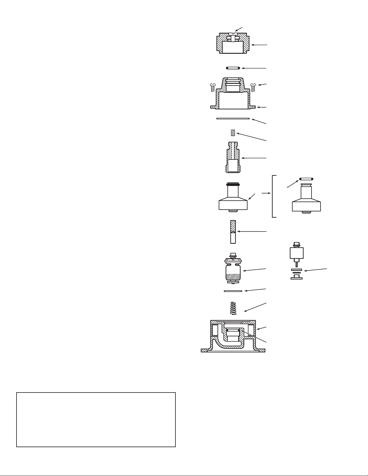
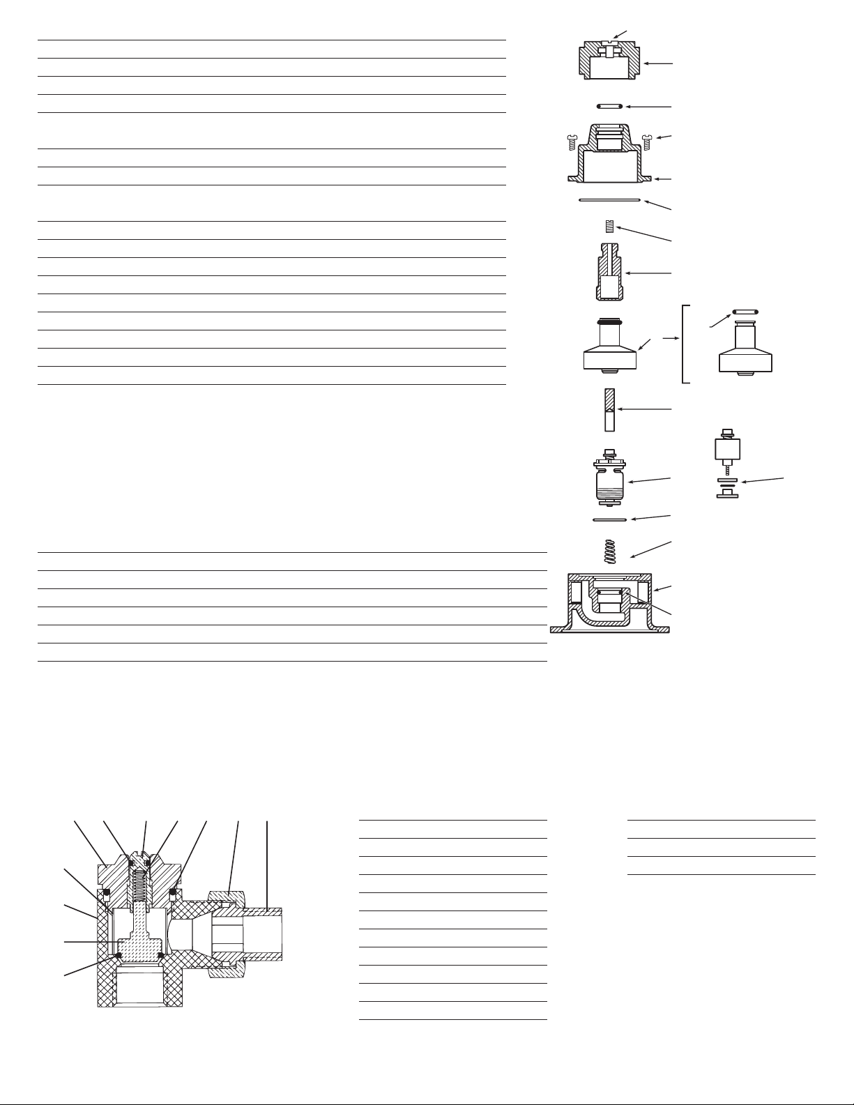
Thermostatic Water Controller Cut-away
Series 61 cut away new
9
3
4
5
6
7
8
11
12
15
17
16
10
2
1
13
14
Series 61 cut away new
9
3
4
5
6
7
8
11
12
15
17
16
10
2
1
13
14
Item Description 1/2” Part No. 3/4” Part No.
1 Handle Screw 7628-00 7628-00
2 Handle 8062-00 8062-00
3 Cover O-Ring — —
4 Cover Screw 7185-00 117-00
5 Cover — —
(Available only in Cover & Spindle Assembly)
6 Body Gasket — —
7 Adjusting Screw 8262-00 8262-00
8 Spindle — —
(Available only in Cover & Spindle Assembly)
9 Thermostat Assembly See Below See Below
10 Thermostat O-Ring — —
11 Pushrod 153-03 153-03
12 Piston, Liner & Backseat Assembly See Below See Below
13 Hot Seat Disc — —
14 Liner Seat O-Ring — —
15 Valve Spring 8223-00 8063-00
16 Body — —
17 Body O-Ring — —
Numbers shown below are for a 1/2” 61-10 and 3/4” 61-25 with standard brass nish and
temperature range of 85-135.Consult price sheets or contact the factory on kits with other ow
rates and temperature ranges.
Item Description Contains 61-10 61-25
A Complete Repair Kit B-C-D-4-11-15 78001-01 78002-01
B O-Ring and Gasket Kit 3-6-10-13-14-17 79959-00 79960-00
C Piston, Liner & Backseat 12-14 72904-11 72905-11
D Thermostat Assembly 9-6 72903-11 72903-11
E Cover & Spindle (Brass) 3-5-7-8 72940-00 72941-00
Cover & Spindle (Chrome) 3-5-7-8 72940-01 72941-01
Does not include parts for stop & checks
Repair Kits and Assemblies
Rebuilding Kit for Inlet Stop & Checks
NOTE:* Components are not included in repair kit.
Item Description
1 Adjustment Stem
2 O-Ring Seal
3 Spring
*4 Bonnet
*5 Body
6 O-Ring Disc Holder
7 O-Ring
8 Strainer
*9 Union Nut
*10 Union Tailpiece
11 Bonnet O-Ring
Repair Kit for Two Stop & Checks
Valve Part No.
1/2” 79902-03
3/4” 79907-12
7
6
5
8
42 9103111
This manual suits for next models
3
Other Lawler Control Unit manuals

Lawler
Lawler 3000 Instruction Manual

Lawler
Lawler NEPTUNE EMX 075 Instruction Manual

Lawler
Lawler 911E Instruction Manual

Lawler
Lawler 410 Instruction Manual

Lawler
Lawler 4000 Series Instruction Manual

Lawler
Lawler 911E Instruction Manual

Lawler
Lawler 570 User manual

Lawler
Lawler 67 Series Instruction Manual

Lawler
Lawler 310 Instruction Manual

Lawler
Lawler 911 E/F Series User manual


