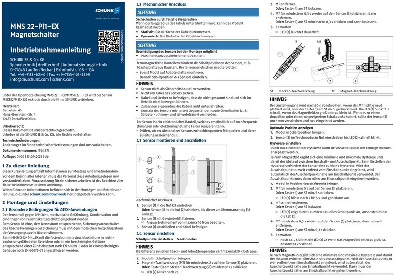
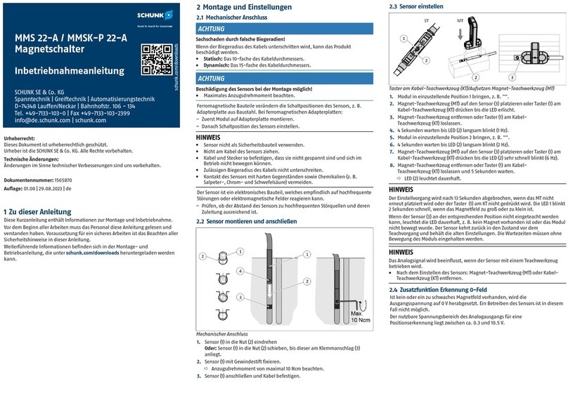
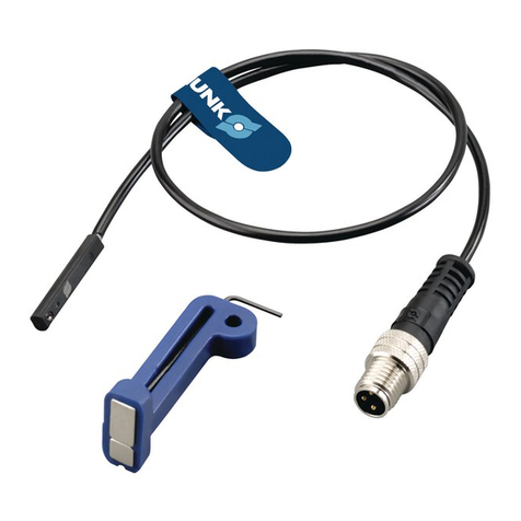
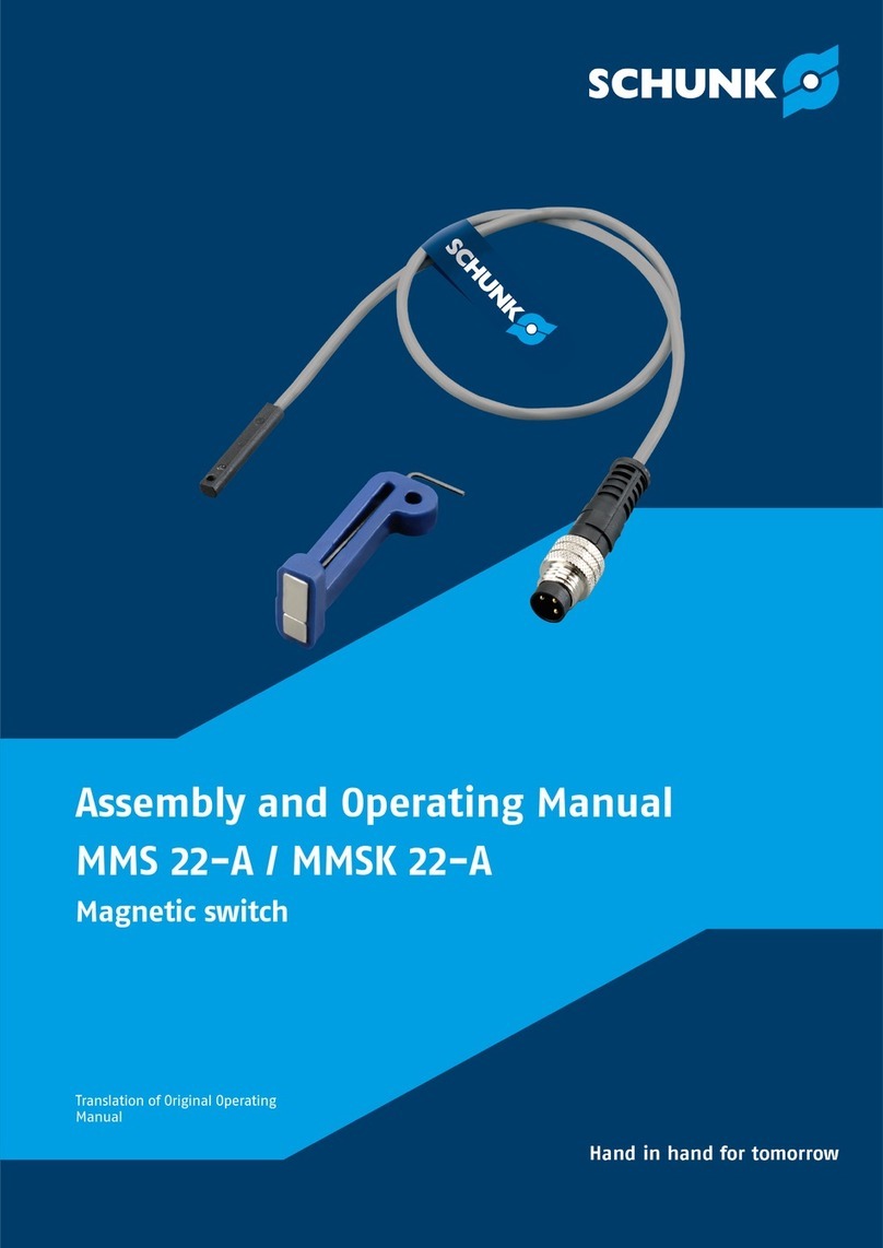
SCHUNK MMS-P 22 User instructions

Assembly and Operating Manual
MMS-P22 / MMSK-P22
Magnetic switch
Translation of Original Operating
Manual

Imprint
2 01.00 | MMS-P22 / MMSK-P22 | Assembly and Operating Manual | en | 1566688
Imprint
Copyright:
This manual is protected by copyright. The author is SCHUNK SE & Co. KG.
All rights reserved.
Technical changes:
We reserve the right to make alterations for the purpose of technical improvement.
Document number: 1566688
Version: 01.00|12/09/2023|en
Dear Customer,
Thank you for trusting our products and our family-owned company, the leading technology
supplier of robots and production machines.
Our team is always available to answer any questions on this product and other solutions. Ask
us questions and challenge us. We will find a solution!
Best regards,
Your SCHUNK team
Customer Management
Tel. +49-7133-103-2503
Fax +49-7133-103-2189
cmg@de.schunk.com
Please read the operating manual in full and keep it close to the product.

General
01.00 | MMS-P22 / MMSK-P22 | Assembly and Operating Manual | en | 1566688 3
1 General
1.1 About this manual
This manual contains important information for a safe and
appropriate use of the product.
This manual is an integral part of the product and must be kept
accessible for the personnel at all times.
Before starting work, the personnel must have read and
understood this operating manual. Prerequisite for safe working
is the observance of all safety instructions in this manual.
1.1.1 Presentation of Warning Labels
To make risks clear, the following signal words and symbols are
used for safety notes.
CAUTION
Material damage!
Information about avoiding material damage.
1.1.2 Applicable documents
lGeneral terms of business *
lCatalog data sheet of the purchased product *
lAssembly‐ and Operating Manual of the SCHUNK-module, on
which the sensor is mounted *
The documents labeled with an asterisk (*) can be downloaded
from schunk.com.
1.1.3 Variants
This operating manual applies to the following variations:
lMMS-P22 / MMSK-P22
lMMS-P22 / MMSK-P22 -SA, with lateral cable outlet
lMMS-P22 / MMSK-P22 -HD, with stainless steel housing

General
4 01.00 | MMS-P22 / MMSK-P22 | Assembly and Operating Manual | en | 1566688
1.2 Warranty
If the product is used as intended, the warranty is valid for 24
months from the ex-works delivery date under the following
conditions:
lObserve the applicable documents, }1.1.2 [/3]
lObserve the ambient conditions and operating
conditions, }2.3 [/5]
1.3 Scope of delivery
The scope of delivery includes
lMagnetic switch MMS-P22 / MMSK-P22 in the version ordered
lAssembly and Operating Manual
lAccessory pack (incl. magnetic teaching tool, ID 301030)

Basic safety notes
01.00 | MMS-P22 / MMSK-P22 | Assembly and Operating Manual | en | 1566688 5
2 Basic safety notes
2.1 Intended use
The product (sensor) is used for sensing a position of a SCHUNK
module via a magnetic control cam or a specific magnetic field.
lThe product is intended for installation in a machine/
automated system. The applicable guidelines for the machine/
automated system must be observed and complied with.
lThe product may only be used within the scope of its technical
data, }3 [/7].
2.2 Inappropriate use
The product is not a safety component in accordance with the EC
Machine Directive 2006/42/EC and must not be used in safety-
relevant parts of machine control units.
2.3 Environmental and operating conditions
Required ambient conditions and operating conditions
Incorrect ambient and operating conditions can make the
product unsafe, leading to the risk of serious injuries,
considerable material damage and/or a significant reduction to
the product's life span.
lMake sure that the product is used only in the context of its
defined application parameters, }3 [/7].
lMake sure that the environment is free from splash water and
vapors as well as from abrasion or processing dust. Exceptions
are products that are designed especially for contaminated
environments.
2.4 Constructional changes
Implementation of structural changes
Modifications, changes or reworking, e.g.additional threads,
holes, or safety devices, can damage the product or impair its
functionality or safety.
lStructural changes should only be made with the written
approval of SCHUNK.

Basic safety notes
6 01.00 | MMS-P22 / MMSK-P22 | Assembly and Operating Manual | en | 1566688
2.5 Personnel qualification
Inadequate qualifications of the personnel
If the personnel working with the product is not sufficiently
qualified, the result may be serious injuries and significant
property damage.
lAll work may only be performed by qualified personnel.
lBefore working with the product, the personnel must have
read and understood the complete assembly and operating
manual.
lObserve the national safety regulations and rules and general
safety instructions.

Technical data
01.00 | MMS-P22 / MMSK-P22 | Assembly and Operating Manual | en | 1566688 7
3 Technical data
Designation MMS-P22 / MMSK-
P22
Ambient temperature [°C]
Min.
Max.
+5
+55
Nominal voltage [VDC]
Min.
Max.
24
12
30
IP rating 67
More technical data is included in the catalog data sheet.
Whichever is the latest version.

Assembly and settings
8 01.00 | MMS-P22 / MMSK-P22 | Assembly and Operating Manual | en | 1566688
4 Assembly and settings
NOTE
The assembly instructions in this chapter are generally
applicable.
Module-specific assembly instructions for the sensor can be
found in the Assembly and Operating Manual for the module,
which can be downloaded at schunk.com
4.1 Mechanical connection
CAUTION
Property damage due to incorrect bending radius!
The product may get damaged if the cable's bending radius is
less than the minimum.
lStatic: 10 times the cable diameter.
lDynamic: 15 times the cable diameter.
CAUTION
Risk of damage to the sensor during assembly!
lObserve the maximal tightening torque.
Ferromagnetic components change the sensor's switching
positions, e.g. adapter plate made of construction steel. For
ferromagnetic adapter plates:
lFirst, install the module on the adapter plate.
lThen adjust the switching position of the sensor.
NOTE
lDo not use the sensor as a safety component.
lDo not pull on the cable of the sensor.
lSecure the cable and connection plug so that they are not
taught and cannot move during operation.
lDo not exceed the permitted bending radius of the cable.
lDo not allow the sensor to come into contact with hard
objects and chemicals (e.g., nitric acid, chromic acid and
sulfuric acid).
The sensor is an electronic component that can be sensitive to
high-frequency interference or electromagnetic fields.
lCheck whether there is sufficient distance between the sensor
and sources of interference and their supply cables.
Assembly and settings
01.00 | MMS-P22 / MMSK-P22 | Assembly and Operating Manual | en | 1566688 9
4.2 Electrical connection
Type of switching : PNP
Switching function: Closing
Variant MMS-P 22: Connector M8
Variant MMSK-P 22: 2 m cable, open
wire strand
1 Brown Supply voltage 3 Blue GND
2 White Output 1 4 Black Output 2
4.3 Installing and connecting the sensor
Mechanical connection
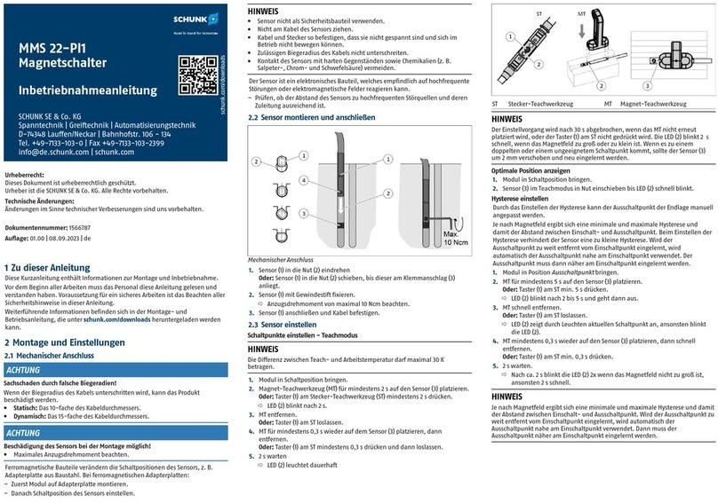
1. Turn the sensor (1) into the groove (2),
Or:Push the sensor (1) into the groove (2) until it reaches the
clamping stop (3).
2. Secure the sensor (1) using the set-screw.
ðObserve the maximum tightening torque of 10Ncm.
3. Connect the sensor (1) and fasten the cable.
4.
Secure the electronics with cable connectors to relieve the stress
on the cable.
ð
Use the ribs on the electronics to fasten the cable.

Assembly and settings
10 01.00 | MMS-P22 / MMSK-P22 | Assembly and Operating Manual | en | 1566688
4.4 Adjusting the sensor
4.4.1 Setting switching points in teach mode
NOTE
The difference between the teach and operating temperatures
must not exceed 30 K.
NOTE
Once the switching points have been set, the environment of the
sensor may no longer be changed.
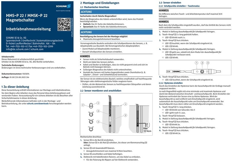
1.
Move module to Switch-off point for switching point 1 position.
2. Press the "Teach" button (2) for 2s.
ðLED 1 (1) flashes after 2s.
3. Briefly press the "Teach" button (2).
ðLED 1 (1) lights up once the switching point has been
taught.
ðLED 2 (3) flashes.
4. Move module to Switch-off point for switching point 2
position.
ðLED 1 (1) goes out as soon as the module leaves Switch-off
point for switching point 1.
ðLED 2 (3) flashes.
5. Briefly press the "Teach" button (2).
ðLED 2 (3) lights up once the switching point has been
taught.
4.4.2 Setting the hysteresis
The switch-off point of the end position can be manually
adjusted by adjusting the hysteresis.
A minimum and maximum hysteresis is defined based on the
magnetic field. This defines the distance between the switch-on
and switch-off point. The sensor prevents a hysteresis that is too
low when the hysteresis is adjusted. If the switch-off point is
taught too far away from the switch-on point, the switch-off
position close to the switch-on point is automatically used. The
switch-off point must then be taught closer to the switch-on
point.

Assembly and settings
01.00 | MMS-P22 / MMSK-P22 | Assembly and Operating Manual | en | 1566688 11
1. Press the "Teach" button (2) for 5s.
ðLED 1 (1) flashes from 2nd to 5th second.
ðLED 1 goes off after 5s.
2. Release the "Teach" (2) button.
3. Move module to Switch-off point for switching point 1
position.
4. Briefly press the "Teach" button (2).
ðLED 1 (1) flashes twice.
5. Move module to Switch-off point for switching point 2
position.
6. Briefly press the "Teach" button (2).
ðLED 2 (3) flashes twice.

Troubleshooting
12 01.00 | MMS-P22 / MMSK-P22 | Assembly and Operating Manual | en | 1566688
5 Troubleshooting
5.1 Sensor not operating
1. Check whether the sensor cable is broken.
2. Check whether the voltage at the sensor is within the
permitted range, }3 [/7].
3. Check whether the LED lights up at the position to be sensed
and that the sensor is operating.
NOTE
If the LED does not light up or the sensor is not operating,
contact SCHUNK Service.
5.2 Sensor is operating, but not as desired
Possible cause Sources of interference Corrective action
The sensor is interfered with or
influenced by external
magnetic or soft magnetic
materials (Fe).
Motors (coils) Increase the distance
between the sensor and
sources of interference
(until the sensor operates
correctly).
Relays
Linear motors
Electrical welding
Magnetized workpieces
(workpieces made of iron (Fe)
or similar materials)
Use finger attachments
made of aluminum.
Magnetized components and
tools made of iron (adapter
plates made, screws or
hexagon socket keys, etc.)
Use components containing
aluminum. V4A screws are
recommended.
The sensor is influenced by a
different sensor.
Same or similar product Increase the distance
between the sensors to at
least 2mm.
The sensor is affected by
deposits of magnetic chips in
the vicinity (in the air gap).
Liquids with magnetic chips or
the like.
Regularly clean the
immediate environment of
the sensor. (The higher the
exposure to such fluids, the
more often it needs to be
cleaned.)
The sensor is affected by the
directly adjacent module.
Built-in magnets in the piston
of the adjacent module
Increase the distance to the
adjacent module to at least
10mm.
NOTE
If these steps do not eliminate the problem, contact SCHUNK
Service for troubleshooting.

Translation of the original declaration of conformity
01.00 | MMS-P22 / MMSK-P22 | Assembly and Operating Manual | en | 1566688 13
6 Translation of the original declaration of
conformity
Manufacturer/
Distributor
SCHUNK SE & Co. KG
Toolholding and Workholding | Gripping Technology | Automation
Technology
Bahnhofstr. 106 - 134
D-74348 Lauffen/Neckar
Product designation: Magnetic switch MMS-P22 / MMSK-P22
ID number 0301370, 0301371
We hereby declare on our sole authority that the product meets the requirements of the
following directives at the time of the declaration.
The declaration is rendered invalid if modifications are made to the product.
lElectromagnetic compatibility (EMC directive) 2014/30/EU
Applied harmonized standards, especially:
EN 60947-5-7:2003 Low-voltage switchgear and controlgear - Part 5-7: Control circuit
devices and switching elements -
Requirements for proximity devices with analogue output (IEC
60947-5-7:2003)
Signed for and on behalf of: SCHUNK SE & Co. KG
Lauffen/Neckar,September2023
i.V. Nico Peper;Director Software and
Electronics;Technology & Innovation

UKCA Declaration of Conformity
14 01.00 | MMS-P22 / MMSK-P22 | Assembly and Operating Manual | en | 1566688
7 UKCA Declaration of Conformity
Manufacturer/
Distributor
SCHUNK Intec Limited
Clamping and gripping technology
3 Drakes Mews, Crownhill
MK8 0ER Milton Keynes
Product designation: Magnetic switch MMS-P22 / MMSK-P22
ID number 0301370, 0301371
We hereby declare that the product complies with all relevant harmonization legislation of
the following directives at the time of declaration.
The declaration is rendered invalid if modifications are made to the product.
lElectromagnetic Compatibility Regulations 2016
Applied harmonized standards, especially:
EN 60947-5-7:2003 Low-voltage switchgear and controlgear - Part 5-7: Control circuit
devices and switching elements -
Requirements for proximity devices with analogue output (IEC
60947-5-7:2003)
Person authorized to compile the technical documentation:
Marcel Machado, address: refer to manufacturer's address
Signed for and on behalf of: SCHUNK SE & Co. KG
Lauffen/Neckar,September2023
i.V. Nico Peper;Director Software and
Electronics;Technology & Innovation

Information on the RoHS Directive, REACH Regulation and Substances of Very High Concern (SVHC)
01.00 | MMS-P22 / MMSK-P22 | Assembly and Operating Manual | en | 1566688 15
8 Information on the RoHS Directive, REACH
Regulation and Substances of Very High Concern
(SVHC)
RoHS Directive
SCHUNK products are classified as "large-scale stationary installations" or as "large-scale
stationary industrial tools" within the meaning of Directive2011/65/EU and its
extension2015/863/EU "on the restriction of the use of certain hazardous substances in
electrical and electronic equipment (RoHS)", or fulfill their intended function only as part of
one. Therefore products from SCHUNK do not fall within the scope of the directive at this time.
REACH Regulation
Products from SCHUNK fully comply with the regulations of Regulation(EC)No.1907/2006
"concerning the Registration, Evaluation, Authorization and Restriction of Chemicals (REACH)"
and its amendment2022/477. SCHUNK attaches great importance to completely avoiding
chemicals of concern to humans and the environment wherever possible.
Only in rare exceptional cases do SCHUNK products contain SVHC substances on the candidate
list with a mass content above0.1%. In accordance with Article. 33(1) of
Regulation(EC)No.1907/2006, SCHUNK complies with its duty to "communicate information on
substances in articles" and lists the components concerned and the substances used in an
overview that can be viewed at schunk.com\SVHC.
Lauffen/Neckar, September 2023 Dr.-Ing. Manuel Baumeister,
Head of Systems Engineering,
Technology & Innovation

SCHUNK SE & Co. KG
Toolholding and Workholding | Gripping Technology |
Automation Technology
Bahnhofstr. 106 - 134
D-74348 Lauffen/Neckar
Tel. +49-7133-103-0
Fax +49-7133-103-2399
info@de.schunk.com
schunk.com
Folgen Sie unsIFollow us
Wir drucken nachhaltigIWe print sustainable
09-2023©2023SCHUNK SE & Co. KG01.00 | MMS-P22 / MMSK-P22 | Assembly and Operating Manual | en | 1566688
Other manuals for MMS-P 22
1
This manual suits for next models
1
Table of contents
Other SCHUNK Switch manuals

SCHUNK
SCHUNK MMS 22-PI2 Training manual

SCHUNK
SCHUNK MMS 22-A Training manual

SCHUNK
SCHUNK MMS 22-PI1 Training manual

SCHUNK
SCHUNK MMS 22-PI2 User instructions

SCHUNK
SCHUNK MMS 22-A User instructions

SCHUNK
SCHUNK MMS-P 22 Training manual

SCHUNK
SCHUNK MMS 22-PI1-EX Training manual

SCHUNK
SCHUNK MMS 22-PI1 User instructions

SCHUNK
SCHUNK MMS 22-PI1-EX User instructions

SCHUNK
SCHUNK MMS 22-PI1-EX Training manual