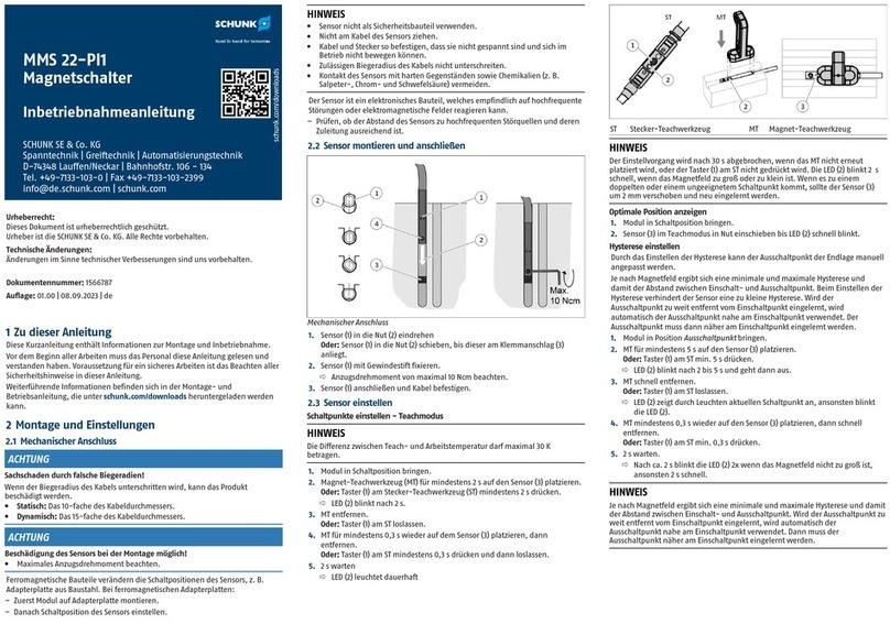
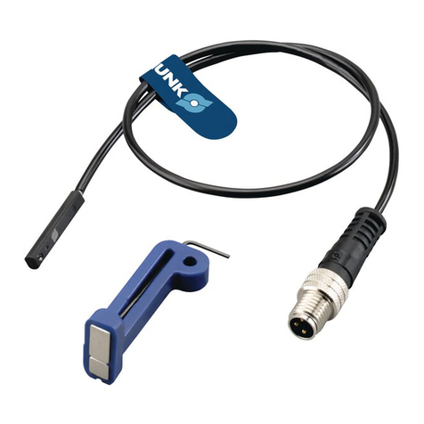
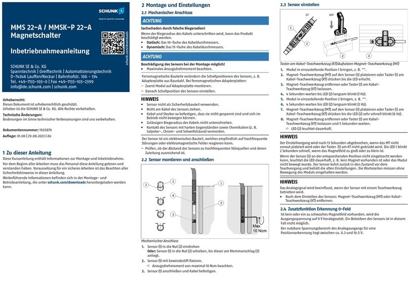
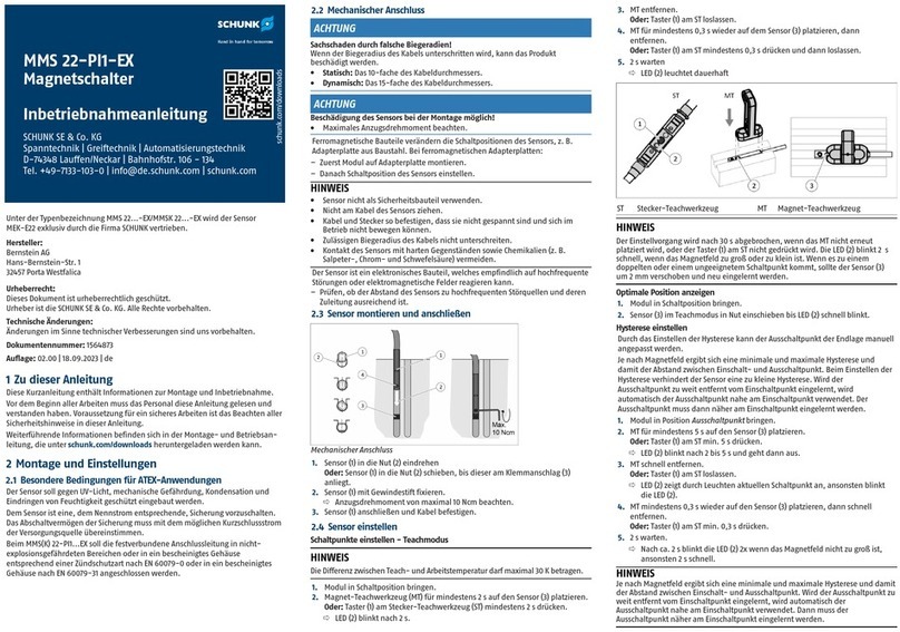
SCHUNK MMS 22-PI2 Training manual

schunk.com/downloads
MMS 22-PI2 / MMSK 22-PI2
Magnetschalter
Inbetriebnahmeanleitung
SCHUNK SE & Co. KG
Spanntechnik | Greiftechnik | Automatisierungstechnik
D-74348 Lauffen/Neckar | Bahnhofstr. 106 - 134
Tel. +49-7133-103-0 | Fax +49-7133-103-2399
info@de.schunk.com | schunk.com
Urheberrecht:
Dieses Dokument ist urheberrechtlich geschützt.
Urheber ist die SCHUNKSE&Co.KG. Alle Rechte vorbehalten.
Technische Änderungen:
Änderungen im Sinne technischer Verbesserungen sind uns vorbehalten.
Dokumentennummer: 1564872
Auflage: 01.00|25.08.2023|de
1 Zu dieser Anleitung
Diese Kurzanleitung enthält Informationen zur Montage und Inbetriebnahme.
Vor dem Beginn aller Arbeiten muss das Personal diese Anleitung gelesen und
verstanden haben. Voraussetzung für ein sicheres Arbeiten ist das Beachten aller
Sicherheitshinweise in dieser Anleitung.
Weiterführende Informationen befinden sich in der Montage- und
Betriebsanleitung, die unter schunk.com/downloads heruntergeladen werden
kann.
2 Montage und Einstellungen
2.1 Mechanischer Anschluss
ACHTUNG
Sachschaden durch falsche Biegeradien!
Wenn der Biegeradius des Kabels unterschritten wird, kann das Produkt
beschädigt werden.
lStatisch: Das 10-fache des Kabeldurchmessers.
lDynamisch: Das 15-fache des Kabeldurchmessers.
ACHTUNG
Beschädigung des Sensors bei der Montage möglich!
lMaximales Anzugsdrehmoment beachten.
Ferromagnetische Bauteile verändern die Schaltpositionen des Sensors, z.B.
Adapterplatte aus Baustahl. Bei ferromagnetischen Adapterplatten:
– Zuerst Modul auf Adapterplatte montieren.
– Danach Schaltposition des Sensors einstellen.
HINWEIS
lSensor nicht als Sicherheitsbauteil verwenden.
lNicht am Kabel des Sensors ziehen.
lKabel und Stecker so befestigen, dass sie nicht gespannt sind und sich im
Betrieb nicht bewegen können.
lZulässigen Biegeradius des Kabels nicht unterschreiten.
lKontakt des Sensors mit harten Gegenständen sowie Chemikalien (z.B.
Salpeter-, Chrom- und Schwefelsäure) vermeiden.
Der Sensor ist ein elektronisches Bauteil, welches empfindlich auf hochfrequente
Störungen oder elektromagnetische Felder reagieren kann.
– Prüfen, ob der Abstand des Sensors zu hochfrequenten Störquellen und deren
Zuleitung ausreichend ist.
2.2 Sensor montieren und anschließen
Mechanischer Anschluss
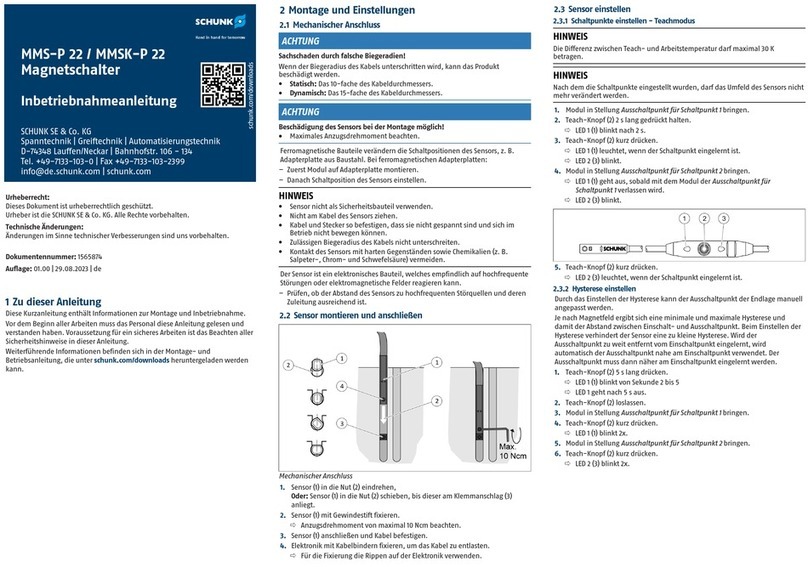
1. Sensor (1) in die Nut (2) eindrehen
Oder: Sensor (1) in die Nut (2) schieben, bis dieser am Klemmanschlag (3)
anliegt.
2. Sensor (1) mit Gewindestift fixieren.
ðAnzugsdrehmoment von maximal 10Ncm beachten.
3. Sensor (1) anschließen und Kabel befestigen.
2.3 Sensor einstellen
Schaltpunkte einstellen - Teachmodus
HINWEIS
Die Differenz zwischen Teach- und Arbeitstemperatur darf maximal 30 K betragen.
1. Modul in Schaltposition bringen.
2. Magnet-Teachwerkzeug (MT) für mindestens 2s auf den Sensor (4) platzieren
Oder: Taster (1) am Stecker-Teachwerkzeug (ST) mindestens 2s drücken.
ðLED (2) blinkt nach 2s.
3. MT entfernen
Oder: Taster (1) am ST loslassen.
Für Schaltpunkt 1: Weiter mit dem nächsten Schritt.
Für Schaltpunkt 2: 10s warten, bis LED (3) blinkt, dann weiter mit dem
nächsten Schritt.
4. MT für mindestens 0,3s wieder auf dem Sensor platzieren, dann entfernen.
Oder: Taster (1) am ST mindestens 0,3s drücken und dann loslassen.
5. 2s warten.
ðLED (2) oder LED (3) leuchtet dauerhaft
ST Stecker-Teachwerkzeug MT Magnet-Teachwerkzeug
HINWEIS
Der Einstellvorgang wird nach 30s abgebrochen, wenn das MT nicht erneut
platziert wird, oder der Taster (1) am ST nicht gedrückt wird. Die LED (2) blinkt 2s
schnell, wenn das Magnetfeld zu groß oder zu klein ist. Wenn es zu einem
doppelten oder einem ungeeignetem Schaltpunkt kommt, sollte der Sensor (4)
um 2mm verschoben und neu eingelernt werden.
Hysterese einstellen
Durch das Einstellen der Hysterese kann der Ausschaltpunkt der Endlage manuell
angepasst werden.
Je nach Magnetfeld ergibt sich eine minimale und maximale Hysterese und
damit der Abstand zwischen Einschalt- und Ausschaltpunkt. Beim Einstellen der
Hysterese verhindert der Sensor eine zu kleine Hysterese. Wird der
Ausschaltpunkt zu weit entfernt vom Einschaltpunkt eingelernt, wird
automatisch der Ausschaltpunkt nahe am Einschaltpunkt verwendet. Der
Ausschaltpunkt muss dann näher am Einschaltpunkt eingelernt werden.
1. Modul in Position Ausschaltpunkt bringen.
2. MT für mindestens 5s auf den Sensor (4) platzieren
Oder: Taster (1) am ST mindestens 5s drücken.
ðLED (2) blinkt nach 2 bis 5s und geht dann aus.
3. MT schnell entfernen
Oder: Taster (1) am ST loslassen.
ðLED (2) zeigt durch Leuchten aktuellen Schaltpunkt an, ansonsten blinkt
die LED (2).
Für Ausschaltpunkt 1: Weiter mit dem nächsten Schritt.
Für Ausschaltpunkt 2: 10s warten, bis LED (3) durch Leuchten den aktuellen
Schaltpunkt anzeigt, andernfalls blinkt LED (3), dann weiter mit dem
nächsten Schritt..
4. MT mindestens 0,3s wieder auf den Sensor (4) platzieren, dann schnell
entfernen
Oder: Taster (1) am ST mindestens 0,3s drücken.
5. 2s warten. Nach ca. 2s blinkt die LED (2) zweimal wenn das Feld nicht zu groß
ist, sonst 2s schnell.
HINWEIS
Je nach Magnetfeld ergibt sich eine minimale und maximale Hysterese und damit
der Abstand zwischen Einschalt- und Ausschaltpunkt. Wird der Ausschaltpunkt zu
weit entfernt vom Einschaltpunkt eingelernt, wird automatisch der
Ausschaltpunkt nahe am Einschaltpunkt verwendet. Dann muss der
Ausschaltpunkt näher am Einschaltpunkt eingelernt werden.


schunk.com/downloads
MMS 22-PI2 / MMSK 22-PI2
Magnetic switch
Commissioning instructions
SCHUNK SE & Co. KG
Toolholding and Workholding | Gripping Technology |
Automation Technology
D-74348 Lauffen/Neckar | Bahnhofstr. 106 - 134
Tel. +49-7133-103-0 | Fax +49-7133-103-2399
info@de.schunk.com | schunk.com
Copyright:
This manual is protected by copyright.
The author is SCHUNK SE & Co. KG. All rights reserved.
Technical changes:
We reserve the right to make alterations for the purpose of technical
improvement.
Document number: 1564872
Edition: 01.00|25/08/2023|en
1 About this manual
This short manual contains information regarding the assembly and initial
operation.
Before starting work, the personnel must have read and understood this
operating manual. Prerequisite for safe working is the observance of all safety
instructions in this manual.
Further information can be found in the assembly and operating manual, which
can be downloaded from schunk.com/downloads.
2 Assembly and settings
2.1 Mechanical connection
CAUTION
Property damage due to incorrect bending radius!
The product may get damaged if the cable's bending radius is less than the
minimum.
lStatic: 10 times the cable diameter.
lDynamic: 15 times the cable diameter.
CAUTION
Risk of damage to the sensor during assembly!
lObserve the maximal tightening torque.
Ferromagnetic components change the sensor's switching positions, e.g.
adapter plate made of construction steel. For ferromagnetic adapter plates:
– First, install the module on the adapter plate.
– Then adjust the switching position of the sensor.
NOTE
lDo not use the sensor as a safety component.
lDo not pull on the cable of the sensor.
lSecure the cable and connection plug so that they are not taught and cannot
move during operation.
lDo not exceed the permitted bending radius of the cable.
lDo not allow the sensor to come into contact with hard objects and chemicals
(e.g., nitric acid, chromic acid and sulfuric acid).
The sensor is an electronic component that can be sensitive to high-frequency
interference or electromagnetic fields.
– Check whether there is sufficient distance between the sensor and sources of
interference and their supply cables.
2.2 Installing and connecting the sensor
Mechanical connection
1. Turn the sensor (1) into the groove (2)
Or: Push the sensor (1) into the groove (2) until it reaches the clamping stop.
2. Secure the sensor (1) using the set-screw.
ðObserve the maximum tightening torque of 10Ncm.
3. Connect the sensor (1) and fasten the cable.
2.3 Adjusting the sensor
Adjusting switching points in teach mode
NOTE
The difference between teach- and operation temperature must not amount
more than 30 K.
1. Place the module in switching position.
2. Place the magnet teach tool (MT) on the sensor (4) for at least 2s
Or: Press the button (1) on the connector teach tool (ST) for at least 2s.
ðThe LED (2) flashes after 2s.
3. Remove the MT
Or: Release the button (1) on the ST.
For switching point 1: Continue with the next step.
For switching point 2: Wait 10s until the LED (3) flashes, then continue with
the next step.
4. Place the MT back on the sensor for at least 0.3s, then remove it.
Or: Press the button (1) on the ST for at least 0.3s and then release it.
5. Wait 2s.
ðThe LED (2) or LED (3) lights up continuously
ST Plug teaching tool MT Magnet teaching tool
NOTE
The setting procedure is canceled after 30s if the MT is not placed on the sensor
again or the button (1) on the ST is not pressed. The LED (2) flashes at 2s intervals if
the magnetic field is too large or too small. If there is a duplicate or unsuitable
switching point, the sensor (4) should be moved by 2mm and taught again.
Setting the hysteresis
The switch-off point of the end position can be manually adjusted by adjusting
the hysteresis.
A minimum and maximum hysteresis is defined based on the magnetic field.
This defines the distance between the switch-on and switch-off point. The
sensor prevents a hysteresis that is too low when the hysteresis is adjusted. If the
switch-off point is taught too far away from the switch-on point, the switch-off
position close to the switch-on point is automatically used. The switch-off point
must then be taught closer to the switch-on point.
1. Place the module in Switch-off point position.
2. Place the MT on the sensor (4) for at least 5s
Or: Press the button (1) on the ST for at least 5s.
ðThe LED (2) flashes after 2 to 5s and goes out.
3. Quickly remove the MT
Or: Release the button (1) on the ST.
ðThe LED (2) lights up to show the current switching point, otherwise the LED
(2) flashes.
For switch-off point 1: Continue with the next step.
For switch-off point 2: Wait 10s until the LED (3) lights up to display the
current switching point, otherwise the LED (3) flashes, then continue with
the next step.
4. Place the MT back on the sensor (4) for at least 0.3s, then quickly remove it
Or: Press the button (1) on the ST for at least 0.3s.
5. Wait 2s. After approximately 2s, the LED (2) flashes twice if the field is not too
large, otherwise it flashes at 2s intervals.
NOTE
A minimum and maximum hysteresis is defined based on the magnetic field. This
defines the distance between the switch-on and switch-off point. If the switch-
off point is taught too far away from the switch-on point, the switch-off position
close to the switch-on point is automatically used. In this case, the switch-off
point closer to the switch-on point must be taught.
Other manuals for MMS 22-PI2
2
This manual suits for next models
1
Table of contents
Languages:
Other SCHUNK Switch manuals

SCHUNK
SCHUNK MMS 22-A User instructions

SCHUNK
SCHUNK MMS-P 22 User instructions

SCHUNK
SCHUNK MMS-P 22 Training manual

SCHUNK
SCHUNK MMS 22-IOL User instructions

SCHUNK
SCHUNK MMS 22-PI1-EX User instructions

SCHUNK
SCHUNK MMS 22-A Training manual

SCHUNK
SCHUNK MMS 22-PI1-EX Training manual

SCHUNK
SCHUNK MMS 22-PI2 User instructions

SCHUNK
SCHUNK MMS 22-PI1-EX Training manual

SCHUNK
SCHUNK MMS 22-PI1 User instructions