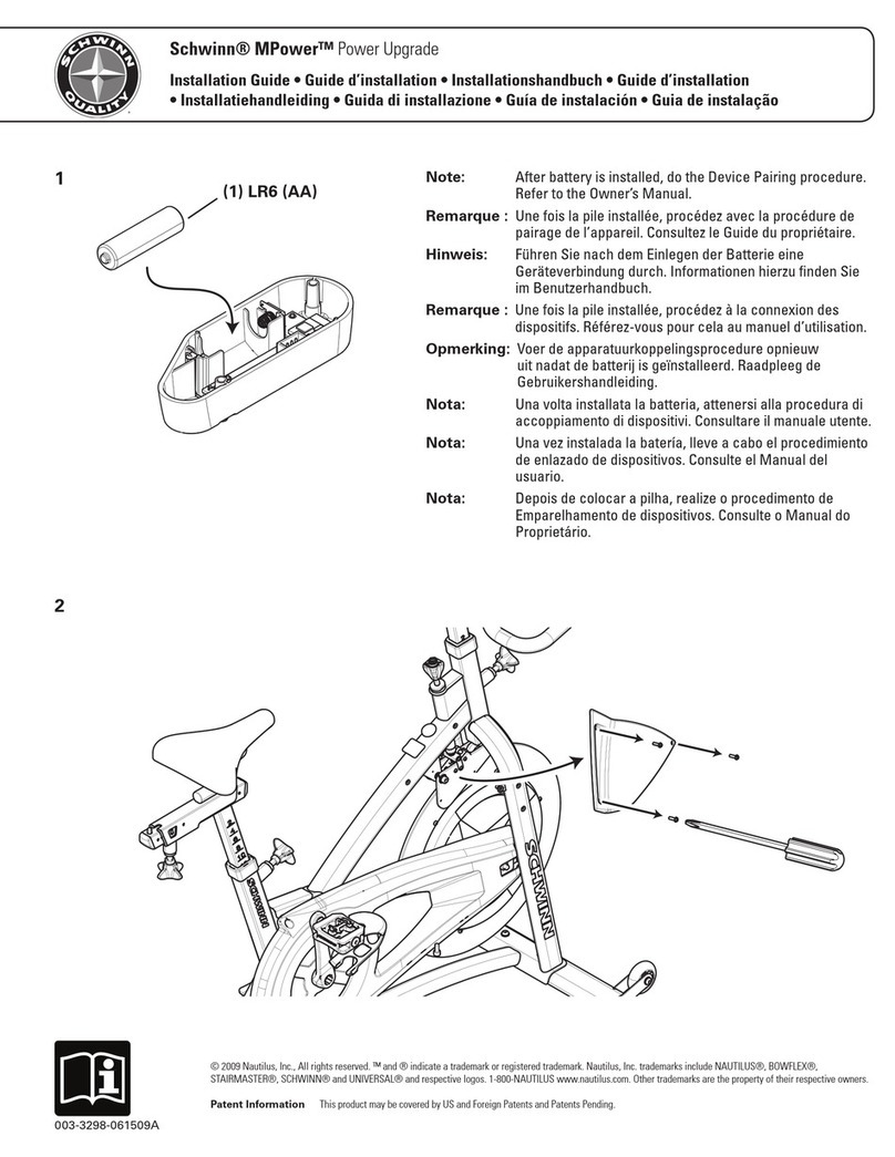
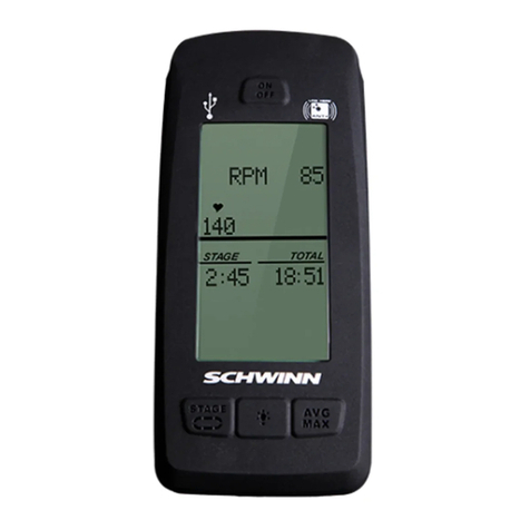
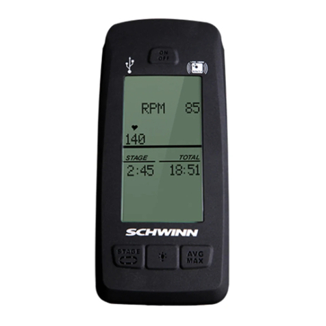
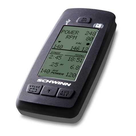
Schwinn MPower Echelon2 Power Upgrade User manual

MPower
™
Echelon2 Console
MPower
™
Echelon2 Power Upgrade
MPower
™
Echelon2 External Wiring Kit
Installation Guide

2 | P a g e M P o w e r E c h e l o n 2 I n s t a l l a t i o n G u i d e
Table of Contents
Introduction ................................................................................................................... 3
Tools Required.............................................................................................................. 3
Console Kit Contents.................................................................................................... 4
Optional Power Upgrade Kit Contents........................................................................ 4
External Wiring Kit Contents........................................................................................ 4
Console Installation on AC Sport and AC Performance............................................ 5
Optional Power Upgrade Kit Installation on AC Sport and AC Performance......... 11
Console Installation on AC Performance Plus ......................................................... 14
Optional Power Upgrade Kit Installation on AC Performance Plus........................ 20
Service Mode Operation............................................................................................. 23
Assigning System Settings........................................................................................ 24
Calibrating Power Sensor........................................................................................... 27
Checking System Settings, Resetting System, and Updating firmware................. 28

3 | P a g e M P o w e r E c h e l o n 2 I n s t a l l a t i o n G u i d e
INTRODUCTION
This installation guide details how to install and setup the following:
Schwinn MPower™ Echelon2 Console, P/N 740-8727
Schwinn MPower™ Echelon2 Optional Power Upgrade, P/N 740-8730
Schwinn MPower™ Echelon2 External Wiring Kit, P/N 740-8875
The following instructions apply to the following models:
Schwinn AC™ Performance
Schwinn AC™ Sport
Schwinn AC™ Sport with Carbon Blue
Schwinn AC™ Performance Plus
Schwinn AC™ Performance Plus with Carbon Blue
NOTE: The console cable must be externally routed on the AC Performance and AC
Sport models. This requires that the External Wiring Kit, 740-8875 be used. The
console cable for the AC Performance Plus is routed internally
TOOLS REQUIRED
Phillips screw driver
2.5mm hex key
3mm hex key
Long nose pliers
NOTE: Tools are not included in the kits.

4 | P a g e M P o w e r E c h e l o n 2 I n s t a l l a t i o n G u i d e
CONSOLE KIT CONTENTS
Item
Description
QTY
1
Console
1
2
Console mount bracket
1
3
RPM (Cadence) sensor
1
4
RPM sensor adapter for AC Sport and AC Performance models
1
5
Console-to-RPM sensor cable (Only used when the optional power upgrade
kit is not installed)
1
6
Connector protective cap
1
7
Cosmetic cap for AC Performance Plus models
1
8
C Cell Batteries
2
9
Console bracket mount screws, M4 x 10mm PHP, for AC Performance Plus
models
3
10
Console bracket mount screws, M5 x 14mm BHCS, for AC Sport and AC
Performance models
2
11
Connector protective cap mount screws, M3 x 12mm SHCS
2
12
Console-to-bracket mount screw, M3 x 6mm PHP
1
13
RPM sensor adapter mount screw, M3 x 6mm PHP (Only used on AC Sport
and AC Performance Plus models)
1
14
Cosmetic cap mount screw, M5 x 14mm (Same as Item 10)
1
15
Cable grommet
1
16
RPM cable saddles
2
17
Cable saddle mount rivets
2
18
CD Rom with Owner’s Manual and Installation Guide
1
OPTIONAL POWER UPGRADE KIT CONTENTS
Item
Description
QTY
1
Sensor assembly
1
2
Console-to-power sensor cable
1
3
RPM-to-Power sensor cable
1
4
Magnet assembly
1
5
Sensor mount screws, M4 x 6mm BHCS (Only 2 screws are used on older
models with two screw mount holes)
3
6
Calibration tool
1
EXTERNAL WIRE KIT CONTENTS
Item
Description
QTY
1
Cable duct assemblies
2

5 | P a g e M P o w e r E c h e l o n 2 I n s t a l l a t i o n G u i d e
CONSOLE INSTALLATION ON AC SPORT AND AC PERFORMANCE BIKES
1. Insert batteries into console. (Figure 1)
Figure 1
2. Mount the console bracket using the two (2) M5 x 14mm button head screws. Tighten the
screws using the 3mm hex key. (Figure 2 and Figure 3)
Figure 2
Figure 3
3. Slide the console onto the bracket. Insert the M3 x 6mm pan head screw and tighten with
the screw driver. (Figure 4)

6 | P a g e M P o w e r E c h e l o n 2 I n s t a l l a t i o n G u i d e
Figure 4
4. Prior to installing the upper conduit, clean head tube with isopropyl alcohol. Allow to air dry.
5. Peel off backing adhesive and align duct part number 740-8875-001 to forward edge and
lower edge of the frame tube (as shown below). Apply normal pressure for 5 seconds.
(Figure 5)
Note: It is recommended that the adhesive set for 24 hours before use.
6. Insert the cable through the slot. (Figure 5)
7. Snap the outer part of the cable duct onto the base with the cable inside. (Figure 6)
Figure 5
Figure 6
8. Using a Philips screw driver, remove the sweat guard (Do not use a power drill in removing
and re-installing). (Figure 7)
9. Route the cable through the sweat guard. (Figure 8)

7 | P a g e M P o w e r E c h e l o n 2 I n s t a l l a t i o n G u i d e
Figure 7
Figure 8
10. Re-mount the sweat guard. (Figure 9 and Figure 10)
Figure 9
Figure 10
11. Plug the console cable RJ45 connector into the console. (Figure 11)
12. Slide the grommet of the cable into the slot on the connector protective cap as shown.
(Figure 11)
13. Attach the protective cap to the bracket using the two (2) M3 x 12mm socket head cap
screws, and tighten with the 2.5mm hex key. (Figure 12)

8 | P a g e M P o w e r E c h e l o n 2 I n s t a l l a t i o n G u i d e
Figure 11
Figure 12
14. Attach the RPM sensor adapter to the RPM sensor using the M3 x 6mm Philips Pan Head
Screw. (Figure 13)
15. Unscrew the M3 x 6mm Philips Pan Head screw holding the RPM sensor cover on and
remove it. (Figure 14 and Figure 15)
Figure 13
Figure 14
Figure 15

9 | P a g e M P o w e r E c h e l o n 2 I n s t a l l a t i o n G u i d e
16. Plug the RPM sensor cable 2-pin connector into the RPM sensor connector and slide the
cable grommet into the slot in the RPM sensor housing. (Figure 16 and Figure 17)
17. Reinstall the RPM sensor cover into the housing, and reinstall the M3 x 6mm Philips Pan
Head screw. (Figure 18 and Figure 19)
Figure 16
Figure 17
Figure 18
Figure 19
18. Remove the top and bottom screw from the front of the chain guard. (Figure 20)
19. Position the RPM sensor as shown and reinstall the two chain guard screws. The RPM
sensor should be about 2 - 3mm away from the flywheel, or about the width of a credit card.
If the RPM sensor is too close, it will rub against the sensor magnet that is embedded in the
flywheel. If the RPM sensor is too far away, the sensor will intermittently pick up a signal
from the magnet or will not pick up any signal at all; this will cause an erratic RPM display, or
no RPM display. (Figure 21)

10 | P a g e M P o w e r E c h e l o n 2 I n s t a l l a t i o n G u i d e
Figure 20
Figure 21
20. Prior to applying the lower conduit, clean the surface of the inner right fork with isopropyl
alcohol and allow to air dry. Peel the non-stick strip off the plastic conduit base. Place it
firmly on the inside of the right hand fork. There should be about one inch gap between
chain guard/rpm sensor bracket and the wire conduit. (Figure 22)
21. Route the wire inside the conduit and snap the conduit outer cover on to the base.
(Figure 23 and Figure 24)
Figure 22
Figure 23
Figure 24

11 | P a g e M P o w e r E c h e l o n 2 I n s t a l l a t i o n G u i d e
Optional Power Upgrade Kit Installation on AC Sport and AC Performance
NOTE: When installing the power upgrade kit, do not use the console-to-RPM sensor
cable (Item 5) from the console kit. This cable is not used when installing the power
upgrade kit. Use the console-to-power cable (Item 2) in the power kit to connect the
console to the power sensor. Use the RPM-to-power cable (Item 3) in the power kit to
connect the RPM sensor to the power sensor; this cable is the shorter cable with a two-
pin connector on each end of the cable. (Figure 25)
Figure 25
1. Repeat Step 1-9, and 11-21 from the console kit installation instructions above.
NOTE: The difference at this point will be that the cable from the console will not be
plugged into the RPM sensor. The RPM sensor cable will have one free end after
installing the RPM sensor on the bike and routing the ROM cable through the cable
duct. The console-to-power cable has different lengths of unshielded wires at each
end as show below in Figure 26 and has RJ45 connectors on both ends. The end
with the shorter length of unshielded wires (shown in the right) plugs into the
console. The end with the longer length of unshielded wires (shown on the left) is
routed through the cable duct and plugged into the power sensor.
Figure 26

12 | P a g e M P o w e r E c h e l o n 2 I n s t a l l a t i o n G u i d e
2. Position rubber boot with magnet (magnet assembly) so that the hex pattern of the boot
lines up with the hex nut on the resistance mechanism. (Figure 27)
3. Slide boot onto hex nut and ensure that boot sits in contact with the black plate of the
resistance mechanism. (Figure 28)
Figure 27
Figure 28
4. Plug console cable into the RJ45 connector, and the RPM cable into the 2-pin connector on
the power sensor. Slide each cable’s grommet into their respective slots in the power
sensor case. (Figure 29)
Figure 29
5. Attach sensor case to the resistance mechanism using the M4 x 6mm button head screws.
Be sure that sensor case sits tight against the black plate of the resistance mechanism.
(Figure 30)

13 | P a g e M P o w e r E c h e l o n 2 I n s t a l l a t i o n G u i d e
Figure 30
6. Reinstall sweat guard. (See Figure 10)

14 | P a g e M P o w e r E c h e l o n 2 I n s t a l l a t i o n G u i d e
Console Installation on AC Performance Plus
1. Insert batteries into console. (Figure 31)
Figure 31
2. Remove handlebars from bike and place on a sturdy working surface.
3. Grab the console-to-RPM cable and note which end has the 2-pin connector.
4. Insert the end of cable with the 2-pin connector into the opening at the top of the handlebar
post. Feed the cable through, with one section of coiled cable being inside the tube, and
one section of coiled cable being outside the tube. The end of the cable should just be
poking out of the end of the tube. (Figure 32 and Figure 33)
Figure 32
Figure 33
5. Place the handlebar back on the bike.
6. Feed the end of the cable out of the end of the head tube. Wear heavy-duty protective
gloves when pulling the end of the cable out of the head tube as there may be sharp edges
inside the head tube. (Figure 34)

15 | P a g e M P o w e r E c h e l o n 2 I n s t a l l a t i o n G u i d e
Figure 34
7. Mount the console bracket using the three (3) M4 x 10mm Philips Pan Head screws, and
tighten the screws. (Figure 35 and Figure 36)
Figure 35
Figure 36
8. Slide the console onto the bracket. Insert the M3 x 6mm pan head screw and tighten with
the screw driver. (Figure 37)
Figure 37

16 | P a g e M P o w e r E c h e l o n 2 I n s t a l l a t i o n G u i d e
9. Plug the console cable RJ45 connector into the console. (Figure 38)
10. Slide the grommet of the cable into the slot on the connector protective cap as shown.
(Figure 38)
11. Attach the protective cap to the bracket using the two (2) M3 x 12mm socket head cap
screws, and tighten with the 2.5mm hex key. (Figure 39)
Figure 38
Figure 39
12. Install the cosmetic cap using a M5 x 14mm BHCS. (Figure 40 and Figure 41)
Figure 40
Figure 41
13. Using a Philips screw driver, remove the sweat guard (Do not use a power drill in removing
and re-installing). Route the cable through the sweat guard. (Figure 42 and Figure 43)

17 | P a g e M P o w e r E c h e l o n 2 I n s t a l l a t i o n G u i d e
Figure 42
Figure 43
14. Unscrew the M3 x 6mm Philips Pan Head screw holding the RPM sensor cover on and
remove it. (Figure 44 and Figure 45)
Figure 44
Figure 45
15. Plug the RPM sensor cable 2-pin connector into the RPM sensor connector and slide the
cable grommet into the slot in the RPM sensor housing. (Figure 46 and Figure 47)
16. Reinstall the RPM sensor cover into the housing, and reinstall the M3 x 6mm Philips Pan
Head screw. (Figure 48 and Figure 49)

18 | P a g e M P o w e r E c h e l o n 2 I n s t a l l a t i o n G u i d e
Figure 46
Figure 47
Figure 48
Figure 49
17. Remove the top and bottom screw from the front of the chain guard. (Figure 50)
18. Position the RPM sensor as shown and reinstall the two chain guard screws. The RPM
sensor should be about 2 - 3mm away from the flywheel, or about the width of a credit card.
If the RPM sensor is too close, it will rub against the sensor magnet that is embedded in the
flywheel. If the RPM sensor is too far away, the sensor will intermittently pick up a signal
from the magnet or will not pick up any signal at all; this will cause an erratic RPM display, or
no RPM display. (Figure 51)
19. Reinstall the sweat guard.

19 | P a g e M P o w e r E c h e l o n 2 I n s t a l l a t i o n G u i d e
Figure 50
Figure 51
20. Install the two cable saddle mounts to the two holes inside the left fork using the two
plastic rivets. (Figure 52 and Figure 53)
Figure 52
Figure 53
21. Secure the cable inside the two saddle clamps as shown. (Figure 54)
Figure 54

20 | P a g e M P o w e r E c h e l o n 2 I n s t a l l a t i o n G u i d e
Optional Power Upgrade Kit Installation on AC Performance Plus
NOTE: When installing the power upgrade kit, do not use the console-to-RPM sensor
cable (Item 5) from the console kit. This cable is not used when installing the power
upgrade kit. Use the console-to-power cable (Item 2) in the power kit to connect the
console to the power sensor. Use the RPM-to-power cable (Item 3) in the power kit to
connect the RPM sensor to the power sensor; this cable is the shorter cable with a two-
pin connector on each end of the cable. (Figure 55)
Figure 55
1. Repeat Step 1-9, and 11-21 from the console kit installation instructions above.
NOTE: The difference at this point will be that the cable from the console will not be
plugged into the RPM sensor. The RPM sensor cable will have one free end after
installing the RPM sensor on the bike and routing the ROM cable through the cable
duct. The console-to-power cable has different lengths of unshielded wires at each
end as shown in Figure 56 and has RJ45 connectors on both ends. The end with the
shorter length of unshielded wires (shown in the right) plugs into the console. The
end with the longer length of unshielded wires (shown on the left) is routed through
the handlebar post to be plugged into the power sensor. After routing the cable
through the post, and reinstalling the post, the RJ45 connector that plugs to the
power sensor will be visible. (Figure 57)
Other manuals for MPower Echelon2 Power Upgrade
8
Table of contents
Other Schwinn Fitness Electronic manuals
Schwinn
Schwinn MPower Echelon2 Power Upgrade User manual

Schwinn
Schwinn MPower Console V2 User manual

Schwinn
Schwinn MPower User manual

Schwinn
Schwinn MPower Echelon2 Power Upgrade Use and care manual

Schwinn
Schwinn MPower Echelon2G Reference guide
Schwinn
Schwinn MPower Console V2 User manual

Schwinn
Schwinn 4IIII Manual

Schwinn
Schwinn MPower Echelon2G User manual
Schwinn
Schwinn MPower Echelon2 Power Upgrade Installation guide
Schwinn
Schwinn MPower Echelon2G User manual