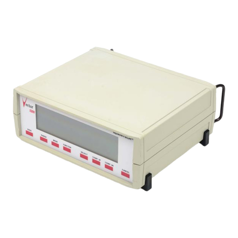
ScienTECH Vector S310 Manual

-~
ARTISAN
®
~I
TECHNOLOGY
GROUP
Your definitive source
for
quality
pre-owned
equipment.
Artisan Technology
Group
Full-service,
independent
repair
center
with
experienced
engineers
and
technicians
on staff.
We
buy
your
excess,
underutilized,
and
idle
equipment
along
with
credit
for
buybacks
and
trade-ins
.
Custom
engineering
so
your
equipment
works
exactly as
you
specify.
•
Critical
and
expedited
services
•
Leasing
/
Rentals/
Demos
• In
stock/
Ready-to-ship
•
!TAR-certified
secure
asset
solutions
Expert
team
ITrust
guarantee
I
100%
satisfaction
All
tr
ademarks,
br
a
nd
names, a
nd
br
a
nd
s a
pp
earing here
in
are
th
e property of
th
e
ir
r
es
pecti
ve
ow
ner
s.
Find the Scientech S310 at our website: Click HERE

Models S310 & S310D
Laser Power and Energy
Meters
Setup and Operating
Procedures
Serial Number___________________
P/N 10190H
5205
Artisan Technology Group - Quality Instrumentation ... Guaranteed | (888) 88-SOURCE | www.artisantg.com

DETECTOR CALIBRATION DATA
Calorimeter # 1:
Model No: ___________
Serial No: ___________
Calibration Wavelength ___________nm or µm
Output Sensitivity (S): ___________V/W
Time Constant (1/e): ___________sec.
Calibration Temp: ___________°C
Sub. Heater Resistance (Rc): ___________ohms
Sub. Heater Voltage (Vh): ___________volts
Sub. Heater Wattage (Wh) ___________watts
Calorimeter # 2:
Model No: ____________
Serial No:
Calibration Wavelength: nm or µm
Output Sensitivity (S): V/W
Time Constant (1/e): sec.
Calibration Temp: °C
Sub. Heater Resistance (Rc): ohms
Sub. Heater Voltage (Vh): volts
Sub. Heater Wattage (Wh): watts
Pyroelectric Detector # 1:
Model No:
Serial No:
Calibration Wavelength: nm or µm
Output Sensitivity: V/J or __________V/mJ S_________
I__________ L_________
Calibration Temp: °C
Pyroelectric Detector # 2:
Model No:
Serial No:
Calibration Wavelength: nm or µm
Output Sensitivity: V/J or __________V/mJ S_________
I_________ L__________
Calibration Temp: °C
Artisan Technology Group - Quality Instrumentation ... Guaranteed | (888) 88-SOURCE | www.artisantg.com
Artisan Technology Group - Quality Instrumentation ... Guaranteed | (888) 88-SOURCE | www.artisantg.com

Thank you for choosing a Scientech laser power and energy meter. Scientech, an ISO 9000
registered company, and employees are pleased to provide you with a product designed for
years of reliable service. Please read this manual completely before using your
indicator. This information will enable you to fully utilize the equipment and should be
located nearby for reference. The indicator is intended to be used only in the manner
outlined in this manual. Misuse of the equipment may cause product failure.
Note: The Models S310 and S310D are identical to each other in every respect except the
analog meter. The S310 has both an analog and digital display. The S310D has only a
digital readout. All references to the S310 are intended to include the S310D except
where noted. Also the words "indicator" and "meter" are synonymous.
TABLE OF CONTENTS
AstralCalorimeter Specifications ............................................................ 1
Vector Pyroelectric Detector Specifications ................................................... 2
UltraCalorimeter Specifications .............................................................. 3
Model S310 Specifications ......................................................................... 4
Environmental Requirements ........................................................................ 5
Unpacking and Setup ............................................................................... 5
Analog Needle Zero Adjust (S310 only) ........................................................ 5
Connecting Detectors .......................................................................... 5
Turn On Sequence .............................................................................. 6
Front Panel Controls .............................................................................. 6
Count Up (Range) Count Down (Mode) ............................................................ 6
Setup ......................................................................................... 6
Group Configuration for AstralCalorimeters ............................................ 7
Group Configuration for VectorPyroelectric Detectors .................................. 8
Group Configuration of UltraSeries 150 Watt Detectors ................................ 9
Range ........................................................................................ 11
Mode ......................................................................................... 11
Stats ........................................................................................ 11
Select ....................................................................................... 12
Cancel ....................................................................................... 12
Operating Procedures ............................................................................. 13
USING THE S310 WITH VECTORPYROELECTRIC DETECTORS ................................................... 13
Energy Mode............................................................................. 13
Average Energy Mode..................................................................... 14
Average Power Mode...................................................................... 14
Statistics Mode......................................................................... 14
External Trigger........................................................................ 14
Pyroelectric Detector Operation With Oscilloscope....................................... 15
HR Battery Installation................................................................. 15
Set Electrical Time Constants for Model PHF02, PHF05 and PHF09.......................... 16
USING THE S310 WITH ASTRALSERIES CALORIMETERS ...................................................... 16
Energy Mode (J)......................................................................... 16
Power Mode (W).......................................................................... 17
Statistics Mode......................................................................... 17
USING THE S310 WITH ULTRASERIES DETECTORS ......................................................... 17
Analog Output........................................................................... 17
Determination of Power and Energy from the Analog Output Assuming 3 V Full Scale........ 18
Calorimeter Operation ............................................................................ 21
Calibration Using Electric Substitution Heating .............................................. 21
Operation of Astral Calorimeters with a Digital Volt Meter ................................... 21
Operation of Astral Calorimeters with an Analog Chart Recorder ............................... 22
Damage Considerations ........................................................................ 24
Remote Interface Language ........................................................................ 26
Remote Interface Language Syntax ............................................................. 26
Remote Interface Language Common Commands and Queries ....................................... 26
IEEE488 Specific Commands............................................................... 31
Factory Recalibration ............................................................................ 32
Limited Warranty ................................................................................. 32
Returned Goods Procedure ......................................................................... 32
Schematics ....................................................................................... 33
Artisan Technology Group - Quality Instrumentation ... Guaranteed | (888) 88-SOURCE | www.artisantg.com
1
ASTRALCALORIMETER SPECIFICATIONS
M odel A C 2500 A C 25H D A C X 25H D A C 2501 A C X 2501 A C 25U V A C 2504
Type A bsorber Surface Surface Surface V olum e V olum e V olum e V olum e
MaxBeam Diam eter 25 m m 25 mm 8m m 25 mm 8m m 25 mm 25mm
Spectral R esponse .25-35 µm .19-12 µm .4-2 µm .266-1.2 µm .4-1.2 µm .19-.36 µm .85-4.2 µm
A verage Pow er(m ax) 10 W
A verage Pow er(m in)* 1 mW
Noise Level 10 µW orµJ
Pow erDensity (m ax) 200 W/cm ² 1.5 kW /cm ² 12 kW /cm ² N ote 1Note 2Note 3Note 4
Peak Pow erDensity (m ax ) 1 MW/cm ² 100 MW/cm ² 800 MW/cm ² N ote 58.5 GW /cm ² N ote 6Note 7
Single Pulse Energy (m ax) 10 J
Energy Density (m ax ) N o te 8Note 9Note 10 N ote 11 N ote 12 N ote 13 N ote 14
Precision < 1%
A ccuracy 3%
R esponse Time 3sec (if attached to a Scientech indicatorand indicatoris in watts mode)
DimensionsDxL (in.)3.75 x 2.23.75 x 2.23.75 x 3.82 3.75 x 2.23.75 x 3.82 3.75 x 2.23.75 x 2.2
(cm ) 9 .53 x 5.69.53 x 5.69.53 x 9.79.53 x 5.69.53 x 9.79.53 x 5.69.53 x 5.6
Weight(lbs) 1.51.51.71.51.71.51.5
(kgs) 0.68 0.68 0.77 0.68 0.77 0.68 0.68
IndicatorCompatibility H 310,H 310D ,H 410,H410D,S310,S310D ,D 200PC ,D200C
M odel A C 5000 A C 50H D A C X 50H D A C 5001 A C X 5001 A C 50U V A C 5004
Type A bsorber Surface Surface Surface V olum e V olum e V olum e V olum e
MaxBeam Diam eter 50 m m 50 m m 16 m m 50 m m 16 m m 50 mm 50mm
Spectral Response .25-35 µm .19-12 µm .4-2 µm .266-1.2 µm .4-1.2 µm .19-.36 µm .85-4.2 µm
A verage Pow er(m ax) 30 W
A verage Pow er(m in) 100 mW
Noise Level 1mW ormJ
Pow erDensity (m ax) 200 W/cm ² 1.5 kW /cm ² 12 kW /cm ² N ote 1Note 2Note 3Note 4
Peak Pow erDensity (m ax ) 1 MW/cm ² 100 MW/cm ² 800 MW/cm ² N ote 58.5 GW /cm ² N ote 6Note 7
Single Pulse Energy (m ax) 30 J
Energy Density (m ax ) N o te 8Note 9Note 10 N ote 11 N ote 12 N ote 13 N ote 14
Precision < 1%
A ccuracy 3%
R esponse Time 3sec (if attached to a Scientech indicatoroperating in watts m ode)
DimensionsDxL (in.)4.75 x 2.34.75 x 2.34.75 x 3.92 4.75 x 2.34.75 x 3.92 4.75 x 2.34.75 x 2.3
(cm ) 12.07 x 5.8 12.07 x 5.812.07 x 9.96 12.07 x 5.812.07 x 9.96 12.07 x 5.812.07 x 5.8
Weight(lbs) 2.92.93.12.93.12.92.9
(kgs) 1.31.31.41.31.41.31.3
IndicatorCompatibilityH310,H 310D ,H 410,H 410D ,S310,S310D ,D 200PC ,D200C
*Calorimeterinstalled in an Iso p eribolenclosure
Note 1: A C 2501,A C 5001 30 W/cm 2@ 1064nm , 23 W/cm 2@ 532nm , 8.5 W/cm 2@ 355nm , 175m W /cm 2@ 266nm
Note 2: A C X 2501,A C X 5001 N ote 1 specs x 8 fo r 400nm to 1.2um
Note 3: AC25UV,A C50U V 50 W/cm 2@ 355nm
Note 4: A C 2504,A C 5004 35W /cm 2@ 1064nm
Note 5: A C 2501,A C 5001 100G W /cm 2@ 1064nm , 78G W /cm 2@ 532nm , 29G W /cm 2@ 355nm , 580M W /cm 2@ 266nm
Note 6: AC25UV,A C50U V Forrep etitive pulses; 101M W /cm 2@ 355nm
Forsingle pulses; 305G W /cm 2@ 355nm
Note 7: A C 2504,A C 5004 125G W /cm 2@ 1064nm
Note 8: A C 2500,A C 5000 MaxJ/cm 2= 1000 x (pulse width)
1/2to a maximum of200 J/cm 2.
Note 9: AC25HD,A C50H D MaxJ/cm 2= 4500 x (pulse width)
1/2to a maximum of14 J/cm 2.
Note 10:ACX25HD,A C X 50H D MaxJ/cm 2= 36,000 x (pulse width)
1/2to a maximum of42.5 J/cm 2.
Note 11: A C 2501,A C 5001 Forrep etitive pulses: 4.1 J/cm 2@ 1064nm , 3.2 J/cm 2@ 532nm , 1.2 J/cm 2@ 355nm ,
24m J/cm 2@ 266nm
Forsingle pulses:8 J/cm 2@ 1064nm , 6.2 J/cm 2@ 532nm , 2.3 J/cm 2@ 355nm ,
46m J/cm 2@ 266nm
Note 12: A C X 2501,A C X 5001 N ote 11 specs x 8 fo r 400nm to 1.2um
Note 13: AC25UV,A C50U V Forrep etitive pulses; 1.1J/cm 2@ 355nm
Forsingle pulses; 40J/cm 2@ 355nm
Note 14: A C 2504,A C 5004 Forrep etitive pulses; 4.8J/cm 2@ 1064nm
Forsingle pulses; 10J/cm 2@ 1064nm
Artisan Technology Group - Quality Instrumentation ... Guaranteed | (888) 88-SOURCE | www.artisantg.com

2
VECTOR PYROELECTRIC DETECTOR SPECIFICATIONS
M odel PH F 02 PH F 05 PH F 09 P 05 P 09
Active Diam eter 2 mm 5mm 9mm 5mm 9mm
Voltage Response 3.0 V/mJ0.8 V/mJ
S,I 15 V/mJ 2.5 V/mJ 1V/mJ
L0.15 V/mJ0.025 V/m
J
0.01 V/mJ
ElectricalD ecay Time 2.0 msec2.0 msec
(RC TimeConstant)
S0.05 msec 0.05 msec 0.05 msec
I0.5 msec 0.5 msec 0.5 msec
L2.5 msec 2.5 msec 2.5 msec
Noise EquivalentEnergy 15 nJ 35 nJ
S,I3nJ 15 nJ 35 nJ
L 150 nJ 750 nJ 3500 nJ
RepRate (m ax) 400 pps 200 pps
S 4000 pps 4000 pps 4000 pps
I 400 pps 400 pps 400 pps
L 80 pps 80 pps 80 pps
Pulse Width (m ax) 50 µsec 100 µsec
(ForCalibrated Response)
S5µsec 5 µsec 5 µsec
I 50 µsec 50 µsec 50 µsec
L 250 µsec 250 µsec 250 µsec
Voltage Output(max.)4.5 V
A verage Power(max) 1W2W2W2W2W
A ccuracy 7% 7% 7% 5% 5%
IndicatorCompatibility S310,S310D ,D 200PC ,D 200P
Model P25 PH F 25 PH D 25 PH D X 25 PHDX 25U V SP 25 SPHF 25 SPHD 25
MaxBeam Diam eter 25 mm 25mm 25mm 7mm 7mm 25mm 25mm 25mm
SpectralR esponse U V to mid-IR.4-2um U V to mid-IR
Average Power(max) 5W* 5W* 5W* 5W* 5W* 5W* 5W* 5W*
Noise EquivalentEnergy 4 µJ
Energy Density (max) Note 2Note 3Note 4Ne 2
Accuracy 5% 5% 8% ^ 8% ^ 8% ^ 5% 5% 8% ^
OutputSensitivity8V/J8V/J2V/J2V/J2V/J8V/J8V/J2V/J
RepRate (m ax) 100 pps 400 pps 40 pps 40 pps 40 pps 100 pps 400 pps 40 pps
Pulse Duration (max) 0.2 msec 0.045 msec 0.2 msec 0.2 msec 0.2 msec 0.2 msec 0.045 msec 0.2 msec
Dimensions (in.)2.4dia.x2.3L 2.4dia.x2.3L 2.4dia.x2.3L 2.4dia.x3.9L 2.4D x3.9L 2.3x2.3x0.62.3x2.3x0.62.3x2.3x0.6
(cm ) 6.1dia.x5.8L 6.1dia.x5.8L 6.1dia.x5.8L 6.1dia.x9.9L 6.1D x9.9L 5.8x5.8x1.45.8x5.8x1.45.8x5.8x1.4
Weight(lbs) 0.90.90.91.11.10.30.30.3
(kgs) 0.41 0.41 0.41 0.50.50.14 0.14 0.14
IndicatorCompatibility H 310,H310D,H 410,H410D,S310,S310D,D200PC,D200P
Model P50 PH F 50 PH D 50 PH D X 50 PHDX50UV SP 50 SPHF 50 SPHD 50
MaxBeam Diam eter 50 mm 50mm 50mm 15mm 15mm 50mm 50mm 50mm
SpectralR esponse U V to mid-IR.4-2um U V to mid-IR
Average Power(max) 10W* 10W* 10W* 10W* 10W* 10W* 10W* 10W*
Noise EquivalentEnergy
Energy Density (max) Note 2Note 3Note 4Ne 2
Accuracy 5% 5% 8% ^ 8% ^ 8% ^ 5% 5% 8% ^
OutputSensitivity2V/J
RepRate (m ax) 50 pps 400 pps 20 pps 20 pps 20 pps 50 pps 400 pps 20 pps
Pulse Duration (max) 0.4 msec 0.045 msec 0.4 msec 0.4 msec 0.4 msec 0.4 msec 0.045 msec 0.4 msec
Dimensions (in.)3.5dia.x2.3L 3.5dia.x2.3L 3.5dia.x2.3L 3.5dia.x3.9L 3.5dia.x3.9L 3x3x0.6 3x3x0.6 3x3x0.6
(cm ) 8.8dia.x5.8L 8.8dia.x5.8L 8.8dia.x5.8L 8.8dia.x9.9L 8.8diax9.9L 7.6x7.6x1.57.6x7.6x1.57.6x7.6x1.5
Weight(lbs) 1.51.51.51.71.70.40.40.4
(kgs) 0.68 0.68 0.68 0.77 0.77 0.18 0.18 0.18
IndicatorCompatibility H 310,H310D,H 410,H410D,S310,S310D,D200PC,D200P
*Fullillum ination ofthesensor
^B eam centered on absorber
Note 1: MaxJ/cm 2=316 x (pulse width)1/2
Note 2: HD models MaxJ/cm 2= 4500 x (pulse width)1/2to a maximum of1.4 J/cm 2.
Maximum pulse width ofthe pyroelectric detectormustbeobserved.
Note 3: HDX m odels MaxJ/cm 2= 36,000 x (pulse width)1/2to a maximum of12.6 J/cm 2.
Maximum pulse width ofthe pyroelectric detectormustbeobserved.
Note 4: HDXUV models MaxJ/cm 2= 18,000 x (pulse width)1/2to a maximum of5.6 J/cm 2.
Maximum pulse width ofthe pyroelectric detectormustbeobserved.
Note 1Ne 1
Note 1Ne 1
16 µJ
ot
ot
ot
ot
Artisan Technology Group - Quality Instrumentation ... Guaranteed | (888) 88-SOURCE | www.artisantg.com
3
ULTRACALORIMETER SPECIFICATIONS
Model UC 150 UC 150HD UC 150HD40 UC 150UV
Type Absorber Surface Surface Surface Volume
Max Beam Size 25 mm dia. 25 mm dia. 40 mm x 40 mm 25 mm dia.
Spectral Response .25-35 µm .19-12 µm .19-12 µm .19-.36 µm
Average Power (max) 150 W
Average Power (min) 10 W
Noise Level 0.1 W
Power Density (max) 200 W/cm² 1.5 kW/cm² 1.5 kW/cm² 50 W/cm²
Peak Power Density (max) 1 MW/cm² 100 MW/cm² 100 MW/cm² 1 GW/cm²
Energy Density (max) 1 J/cm²* 14 J/cm²** 14 J/cm²** 15 J/cm²
Precision < 1%
Accuracy 5%
Response Time Sensor dependent
Dimensions (in.) 4.9H x 3.4 x 4.0D
(cm) 12.5H x 8.6W x 10.2D
Weight (lbs) 2.7
(kgs) 1.2
Indicator Compatibility S310, S310D
*Laser pulse duration of 1 µsec
**Laser pulse duration of 10 µsec
ABSORPTION OF HD ABSORBER vs WAVELENGTH
50
55
60
65
70
75
80
85
90
95
100
200
210
250
300
305
310
315
325
335
350
355
360
385
400
420
440
450
500
530
545
550
595
600
610
635
650
675
850
1060
1300
1480
2000
2100
10600
WAVELENGH [nm]
% ABSORPTION
CAUTION: SPECULAR REFLECTION
NOTE: Please exercise caution when using HD detectors. They exhibit spectral reflection of between
7% and 33%, of the input power, back out of the aperture. Please refer to the preceding bar graph to
determine the reflectance for the wavelength you are measuring. These detectors should be treated as a partial
mirror or any other type of reflective optic and the appropriate caution level observed, especially at the CO2
wavelength.
Artisan Technology Group - Quality Instrumentation ... Guaranteed | (888) 88-SOURCE | www.artisantg.com

4
MODEL S310 SPECIFICATIONS
Model S310 S310D
Display 4 digitLCD with selectable4digitLCD
analog meter movement
R anges (Watts & Joules FullScale) 10.00 m (Watts only),100.0 m,1.000,10.00 and AUTO (Watts only)
(Whenconnected to 25 mm calorimeter)
R anges (Watts & Joules FullScale) 300.0 m,3.000,30.00 and AUTO (Watts only)
(Whenconnected to 50 mm calorimeter)
R anges (Watts & Joules FullScale) 3.000 m,30.00 m,300.0 m,3.000,30.00,AUTO
(Whenconnected to pyroelectric sensor) W ith HR Detectors > 3.000 µ*,30.00 µ*,300.0 µ ,3.000 m,30.00 m,AUTO
Range (Watts FullScale) 150.0
(Whenconnected to Ultra calorimeter)
Maximum Rep.Rate with Calorimeters (Joules Mode) Calorimeter D ependent(1 pulse every 60 to 90 sec.)
Maximum Rep.Rate for Collecting Data in750pps
Statistics Modewith Pyroelectric Sensor
Response Time-Watts Mode Calorimeter D ependent
(Whenconnected to calorimeter) 3 to 10 seconds
Dimensions (H X W X D)(inches) 4.68 X 8.83 X 7.83
(cm ) 11.89 X 22.43 X 19.89
PowerR equirem ent 120 Volt,60 Hz± 10 % or 220 Volt,50 Hz± 10 %
Operating Temperature 5° C to 40° C
*Not available in long pulse setting on PHF02, PHF05, and PHF09
CE Mark Certification: All of the detectors listed in this manual have been certified for the european CE
mark except the following:
1. All of the Ultra™ Series calorimeters: Model UC150, UC150UV, UC150HD, UC150HD40.
2. All of the Vector Series slim profile pyroelectric detectors: Models: SP25, SPHF25, SPHD25,
SP25YAG, SP25UV, SP25AL, SP50, SPHF50, SP50YAG, SP50UV, SP50AL.
Artisan Technology Group - Quality Instrumentation ... Guaranteed | (888) 88-SOURCE | www.artisantg.com
5
ENVIRONMENTAL REQUIREMENTS
This product is intended for indoor use at altitudes up to 2000 meters, Pollution Degree 2 in accordance with
IEC 664 and transient overvoltages according to Installation Categories (Overvoltage Categories) II. Note that
each of the above detectors will not pass the IEC 801 Publication, Part 3, Radiated Electromagnetic Field
Requirements. The system, meter and detector, is designed to measure radiation within the test's radiation
band. The detectors were held outside the radiated electromagnetic field during this test. It is up to the user
to be aware of RF fields present during measurements and their effects if any on those measurements.
UNPACKING AND SETUP
The meter, detectors, and accessories are shipped in custom packing materials. All packing materials should
be saved for future damage free shipments. Before making any connections, verify that the power (VAC)
requirement shown on the power entry module is compatible with the actual AC power outlet to which the
indicator will be connected. insert into the fuse holder. Plug the fuse holder back into the power entry
module. The power requirement of the instrument is easily changed by removing the fuse holder and
voltage selector which is the center portion of the power entry module. To remove, insert a screwdriver
into the right side of the fuse holder and pry out. Slide the voltage selector out, flip over and re-insert into
the fuse holder. Plug the fuse holder back into the power entry module.
Analog Needle Zero Adjust (S310 only)
The black slotted button located just below the display allows screwdriver adjustment to set the analog needle
to zero. This adjustment should be made before connecting the detector.
Connecting Detectors
Refer to the following drawing of the S310 rear panel. A 3 meter mini-DIN type cable with "D" shaped
connectors comes with Astral and Ultra calorimeters. A 3 meter BNC type cable comes with Vector
pyroelectric detectors. The input jacks on the rear panel of the S310 are labeled "Ultra", "Vector", and
"Astral" for hook up of these three types of detectors. Note: Only one detector should be plugged in at any
time. Note that the flat side of the DIN type cables should be oriented up when plugging in to the S310. Also
included with each detector is a 1/2" diameter mounting post for installing the detector to your working
surface. An optional mounting base, Scientech Model 301-019, is also available for holding the detector/post
assembly upright. Astral calorimeters are sensitive to all types of thermal input. Due to handling of the
calorimeter during setup and possible environmental temperature differences, thermal gradients may exist in
the calorimeter. Several minutes before usage may be required to allow the calorimeter to reach thermal
equilibrium. Note: When using a 25 mm Astral calororimeter for measuring average power levels below 30
mW and single pulse energy levels below 30 mJ, a Scientech Model 36-0203A, Isoperibol Enclosure, is
required. The isoperibol enclosure should not be used at average power levels above 30 mW, and single
pulse energy levels above 100 mJ because unwanted heat build up will occur.
Artisan Technology Group - Quality Instrumentation ... Guaranteed | (888) 88-SOURCE | www.artisantg.com

6
S310 Rear Panel
S310 Front Panel
Turn On Sequence
The S310 cycles through a self-calibration sequence whenever it is turned on. The display will show all
segments until completion of the self-calibration period which takes about 25 seconds. At the end of this
sequence the unit will revert to its operational state in its last used configuration.
FRONT PANEL CONTROLS
Count Up (Range) Count Down (Mode)
The RANGE and MODE buttons are used to change the numeric entry in the display when in statistics mode,
average energy mode, and calibration and setup modes. The 4 digit LCD allows numeric entry from .0001 to
9999. The decimal place floats to the right as you hold down the RANGE button to achieve larger values
(less resolution) and to the left as you hold down the MODE button to achieve smaller values (greater
resolution).
Setup
The SETUP button controls the process by which you configure the instrument and later recall the
configuration to be used, viewed, and/or changed. Pushing the CANCEL button at any time will terminate
this process with no changes. The large display will show the current value entered. The range digits will
show a two character mnemonic for the current parameter. Briefly pressing the SELECT button always
advances the configuration to the next step. Holding down the SELECT button places the S310 in its
Artisan Technology Group - Quality Instrumentation ... Guaranteed | (888) 88-SOURCE | www.artisantg.com

7
operational state and implements any changes to the group configuration made up to this point. There are
four setup groups which can be configured and recalled by pressing the SETUP button.
To choose one of four setup groups press the SETUP button. The setup group last used (1, 2, 3, or 4) will
appear in the display. To move to the next group press the SETUP button again. To select a setup group
press the SELECT button when the desired group appears in the display. If the SELECT button is not pushed
within a few seconds, the group number displayed will be activated (return to the current configuration for
operation). The default settings for the groups are 1: Astral Calorimeter, 2: Pyroelectric detector, 3: HR
Pyroelectric detector, 4: Ultra Calorimeter.
To observe each element of the current settings in the group press the SELECT button after each setting. To
change settings, press the SETUP button until the desired setting appears, then press the SELECT button.
Group Configuration for AstralCalorimeters
1. Select the desired setup group to configure by pressing the SETUP button repeatedly until the desired
group number appears then press the SELECT button.
2. Press the SETUP button until the calorimeter annunciator “CAL” appears in the display. Press the
SELECT button to activate the calorimeter configuration program.
3. The "tc" (time constant) annunciator now appears in the display. Press the count up (RANGE) and count
down (MODE) buttons to change the number in the display to match the time constant number listed on
the serial tag of your calorimeter. Press the SELECT button to enter the time constant value to memory.
4. The "SP" (speed) annunciator now appears in the display. Press the count up (RANGE) button to speed up
or count down (MODE) button to slow down the response time of the meter. Press the SELECT button
when the desired number appears in the display. The following settings can be fine tuned to your
preference of speed versus overshoot. We recommend these initial settings:
AC2500, AC25HD, ACX25HD 103.0
AC2501, ACX2501, AC25UV, AC2504 136.0
AC5000, AC50HD, ACX50HD 100.0
AC5001, ACX5001, AC50UV, AC5004 120.0
5. The "Cd" (calorimeter delay) annunciator now appears in the display. The calorimeter delay feature
prohibits the display of energy if a pulse is fired before the entered time (1 to 255 seconds) elapses. The
calorimeter must reach environmental thermal equilibrium before a subsequent pulse is fired or low
energy measurements will occur. To set the time delay between pulses use the count up (RANGE) and
count down buttons (MODE) buttons to enter the time in seconds. Press the SELECT button after the time
has been entered. The following time delays are recommended:
AC2500, AC25HD 60 seconds
AC2501, AC25HD, AC2504 60 seconds
AC5000, AC50HD 90 seconds
AC5001, AC50UV, AC5004 90 seconds
6. The "At" (attenuation) annunciator now appears in the display. If no attenuator is being used in
conjunction with the calorimeter, the attenuation factor in the display must be set at 1.000 since this value
is a display multiplier. Attenuation multipliers from .0001 to 9999 can be entered into the displayed value.
Use the count up (RANGE), count down (MODE) buttons to change the attenuation factor. Press the
SELECT button to enter the attenuation factor to memory.
Artisan Technology Group - Quality Instrumentation ... Guaranteed | (888) 88-SOURCE | www.artisantg.com

8
7. If The S310 has the optional IEEE488 interface, the REMOTE annunciator will appear along with the
digital interface previously selected; r232 (RS232) or IEEE (IEEE488). Press the SETUP button to toggle
the interface between r232 (RS232) and IEEE (IEEE488). Press the SELECT button when the desired
interface appears in the display.
8. If the optional IEEE488 interface was not installed, the "br" (baud rate) annunciator for setting up the
RS232 interface appears in the display along with the baud rate previously selected. To change the baud
rate press SETUP button until the desired baud rate appears in the display. One of the following baud
rates can be selected: 300, 1200, 2400, 9600, and 19,200. When the preferred baud rate appears in the
display press the SELECT button.
9. The "PA" (parity) annunciator now appears in the display. Press the SETUP button to select none, even,
or odd parity. Press the SELECT button to enter the parity of choice to memory
10. The "HS" (handshake) annunciator now appears in the display. Press the SETUP button until your choice
of none (nOnE), on/off (onoF), or clear to send (CtS) appears in the display. Press the SELECT button
when your choice is displayed to enter the handshake to memory.
11. If IEEE488 has been selected, the "bA" (bus address) annunciator appears with the default bus address.
Bus addresses from 0 to 30 may be selected by pressing the count up (RANGE) count down (MODE)
buttons followed by the SELECT button. Once the remote interface has been setup, the group annunciator
will appear. Press the SELECT button or simply wait a few seconds and the group will automatically be
selected for operation.
Group Configuration for VectorPyroelectric Detectors
1. Select the desired group to be configured.
2. Press the SETUP button until the "PYro" annunciator appears. Immediately press the SELECT button to
select the pyroelectric detector configuration program. Either the "V/J" annunciator or the "V/mJ"
annunciator and a detector sensitivity number will appear in the display.
3. Press the SETUP button to toggle between the V/J and V/mJ entries. The output sensitivity of the
pyroelectric detector in V/J or V/mJ is listed on the serial tag of your detector. Use the count up
(RANGE) and count down (MODE) buttons to enter the V/J or V/mJ value. Press the SELECT button to
enter the value to memory. Do not push the SELECT button before entering the sensitivity number or the
next setup stage will be entered.
4. The "SP" (speed) annunciator now appears in the display. Press the SETUP button to toggle between bL
(coated black detector) or hF (high frequency) detector. If the detector Model No. includes the letters
“HF”, press the SELECT button when the hF annunciator appears in the display. If the detector surface
is black (does not have the letters “HF” in the Model No.) press the SELECT button when the "bL"
annunciator appears in the display.
5. The "AUTO, SET CAL" annunciators now appear in the display (only if watts mode was selected prior to
group configuration). This is the transfer calibration function. This allows you to adjust the output
sensitivity of the pyroelectric detector while in operation enabling you to match the average power
reading of the S310 to that of the NIST certified detector. Typically a beam splitter is used with the
detector to be calibrated in one beam path and the NIST certified detector in the other beam path. While
using the S310 with the detector to be calibrated and the NIST standard in an optical calibration, use the
count up (RANGE), count down (MODE) buttons, which change the V/J or V/mJ settings, to make the
Artisan Technology Group - Quality Instrumentation ... Guaranteed | (888) 88-SOURCE | www.artisantg.com

9
displayed value of the S310 power reading the same as the NIST standard. Press the SELECT button
when the readings match.
6. The "At" (attenuation) annunciator now appears in the display. If no attenuator or correction factor is to
be applied to the displayed value, the setting should be 1.000. If a multiplier is to be applied to the
displayed value, use the count up (RANGE), count down (MODE) buttons to enter the multiplier value.
Press the SELECT button to enter the value to memory.
7. The REMOTE annunciator now appears along with the digital interface previously selected; r232 (RS232)
or IEEE (IEEE488). Press the SETUP button to change the interface between r232 (RS232) and IEEE
(IEEE488). Press the SELECT button when the desired interface appears in the display.
8. If RS232 has been selected, the "br" (baud rate) annunciator appears in the display along with the baud
rate previously selected. To change the baud rate press the SETUP button repeatedly until the desired
baud rate appears in the display. One of the following baud rates can be selected: 300, 1200, 2400, 9600,
and 19,200. When the preferred baud rate appears in the display press the SELECT button.
9. The "PA" (parity) annunciator now appears in the display. Press the SETUP button to select none, even,
or odd parity. Press the SELECT button to enter the parity choice to memory
10. The "HS" (handshake) annunciator now appears in the display. Press the SETUP button until your choice
of none (nOnE), on/off (onoF), or clear to send (CtS) appears in the display. Press the SELECT button
when your choice is displayed to enter the handshake to memory.
11. If IEEE488 has been selected, the "bA" (bus address) annunciator appears with the default bus address.
Bus addresses from 0 to 30 may be selected by pressing the count up (RANGE) count down (MODE)
buttons followed by the SELECT button. Once the remote interface has been setup, the group annunciator
will appear. Press the SELECT button or simply wait a few seconds and the group will automatically be
selected for operation.
Group Configuration of UltraSeries 150 Watt Detectors
1. Select the desired group to be configured.
2. Press the SETUP button until the "ULtr" annunciator appears in the display. Immediately press the
SELECT button to select the Ultra detector configuration program. The "SET CAL" (calibration)
annunciator now appears in the display. Press the count up (RANGE) and count down (MODE) buttons to
select the calibration constant (mV/W) value listed on the serial tag of your Ultra detector. Press the
SELECT button to enter the calibration constant value to memory.
3. The "SP" (speed) annunciator now appears in the display. Press the count up (RANGE) button to speed up
or count down (MODE) button to slow down the response time of the meter. Press the SELECT button
when the desired number appears in the display. We recommend initially setting the speed to 0.3. Press
the SELECT button to enter the speed setting to memory.
4. The "At" (attenuation) annunciator now appears in the display. If no attenuator is being used in
conjunction with the detector, the attenuation factor in the display must be set at 1.000 since this value is
a display multiplier. Attenuation multipliers from .0001 to 9999 can be entered into the displayed value.
Use the count up (RANGE), count down (MODE) buttons to change the attenuation factor. Press the
SELECT button to enter the attenuation factor to memory.
Artisan Technology Group - Quality Instrumentation ... Guaranteed | (888) 88-SOURCE | www.artisantg.com

10
5. The REMOTE annunciator now appears along with the digital interface previously selected; r232
(RS232) or IEEE (IEEE488). Press the SETUP button to change the interface between r232 (RS232) and
IEEE (IEEE488). Press the SELECT button when the desired interface appears in the display.
6. If RS232 has been selected, the "br" (baud rate) annunciator appears in the display along with the baud
rate previously selected. To change the baud rate press SETUP button until the desired baud rate appears
in the display. One of the following baud rates can be selected: 300, 1200, 2400, 9600, and 19,200.
When the preferred baud rate appears in the display press the SELECT button.
7. The "PA" (parity) annunciator now appears in the display. Press the SETUP button to select none, even,
or odd parity. Press the SELECT button to enter the parity choice to memory
8. The "HS" (handshake) annunciator now appears in the display. Press the SETUP button until your choice
of none (nOnE), on/off (onoF), or clear to send (CtS) appears in the display. Press the SELECT button
when your choice is displayed to enter the handshake to memory.
9. If IEEE488 has been selected, the "bA" annunciator appears with the default bus address. Bus addresses
from 0 to 30 may be selected by pressing the count up (RANGE) count down (MODE) buttons followed
by the SELECT button. Once the remote interface has been setup, the group annunciator will appear.
Press the SELECT button or simply wait a few seconds and the group will automatically be selected for
operation.
Artisan Technology Group - Quality Instrumentation ... Guaranteed | (888) 88-SOURCE | www.artisantg.com

11
Range
The RANGE button is used to select the range most appropriate for the power or energy level to be measured.
On the S310 only, held down the RANGE button to toggle the analog meter on or off. The appropriate ranges
will be automatically determined by the type of detector which has been programmed into the group which
has been selected.
1. Press the range button each time to move to the next range. Not pushing the RANGE button when the
desired range appears in the display automatically activates the range after a few seconds and returns the
S310 to its operational state.
2. To turn the analog meter on or off, press and hold the RANGE button, then release after the meter appears
or disappears (S310 only).
Mode
The MODE button allows selection of the type of measurement to be made and units of measure to be
displayed; scientific notation or µ, m annunciators. The different measurement modes available are:
When configured for a pyroelectric detector: Energy (J), Avg. Energy (AVG J), Power (W), and Volts (V).
When configured for a calorimeter: Power (W), Energy (J).
When configured for Ultra detector: Power (W) only.
1. Briefly press the MODE button each time a different mode setting is wanted. Not pushing the MODE
button when the desired mode appears in the display automatically activates that mode after a few
seconds and returns the S310 to its operational state.
2. To select scientific notation or µ and m annunciators, press and hold the MODE button and release when
the desired configuration appears.
Stats
Note: When using the PHF09 pyroelectric detector in the long pulse setting, a manual range must be
selected when running statistics. The STATS button provides statistical analysis of a series of energy
readings (pulses). The average energy, minimum energy, maximum energy, standard deviation, and
coefficient of variation are automatically calculated after each run. Runs of up to 1000 pulses (pulse
population) can be entered.
1. To enter into statistics mode press the STATS button. If you are using a pyroelectric detector, the joules
mode and range selected prior to statistics mode are automatically activated. The pulse population
previously selected along with the STATS annunciator and flashing SET annunciator appear in the
display.
2. Press the count up (RANGE) and/or count down (MODE) buttons to change the display to the desired
number of energy readings to be collected. You may select up to 1000 energy measurements for the pulse
population. Press the SELECT button to enter the pulse population to memory. The "STATS"
annunciator will flash indicating the S310 is ready to start a new run.
3. Press the SELECT button to begin collecting new data. The S310 will automatically stop when the pulse
population has been collected.
Artisan Technology Group - Quality Instrumentation ... Guaranteed | (888) 88-SOURCE | www.artisantg.com

12
4. The STATS button must be pressed to recall each data point: the number of pulses collected, the
average energy (AVG), minimum energy (MIN), maximum energy (MAX), standard deviation (SIGMA),
and coefficient of variation (CV%). After recalling the data, the flashing STATS annunciator indicates
the S310 is ready for a new run.
5. Press the SELECT button to begin a new run, or the CANCEL button to exit statistics mode.
Each time a new run begins, data from the previous run is lost. If statistical data is to be automatically
registered, it must be done so through the digital interface.
Select
The SELECT button activates a particular mode or function. Holding down the SELECT button will revert
the S310 to its operational state during group setup. Any changes made during group setup prior to holding
down the SELECT button will be implemented.
Cancel
The CANCEL button reverts the S310 to its operational state during group setup. Any changes made during
group setup prior to pressing the CANCEL button will not be implemented. Pressing the CANCEL button
is the exit out of statistics mode and also is used to zero the display when using a calorimeter in watts
mode.
Artisan Technology Group - Quality Instrumentation ... Guaranteed | (888) 88-SOURCE | www.artisantg.com

13
OPERATING PROCEDURES
USING THE S310 WITH VECTORPYROELECTRIC DETECTORS
Pyroelectric detector models P25, P50, SP25, SP50, P05, and P09 are coated with a special black absorbing
material which provides a very flat spectral response over a broad wavelength band. Models PHF25, PHF50,
SPHF25, SPHF50, PHF02, PHF05, and PHF09 have a partially absorbing, partially reflecting chromium
coating. The relative spectral responses of these detectors are given below.
RELATIVE SPECTRAL RESPONSE
20
30
40
50
60
70
80
90
100
0.1 1 10 100
WAVELENGTH [microns]
PERCENT ABSORPTION
P and SP
HR-P
PHD, PHDX*
and SPHD
HR-PHF
PHF and SPHF
*HDX Limited to 0.4 to 2.0 microns
X
PHDXUV
Before using your Vector joulemeter system, please review the energy density formulas given in the chart on
page 2. Familiarize yourself with all of the specifications of the detector models which you are using. A
damage test slide is provided with each P and PHF type detectors, but not with HD type detectors. Fire the
beam at the test slide before using the detector to be sure you are operating under safe conditions.
Configure One of the Four Groups for the Pyroelectric Detector to be Used (See Page 7).
Energy Mode
Press the MODE button (repeatedly, if need be) until the “J” annunciator appears in the display. Press the
SELECT button or simply wait a few seconds and the joules mode will automatically be activated. Press the
range button (repeatedly, if need be) to select desired range. AUTO range may be selected if the energy
levels of repetitive pulses are to be measured. However, do not select AUTO range if you want to measure
single pulse energy or pulses running at repetition rates lower than 10 Hz.
The energy level of the laser pulses will be displayed on the front panel LCD. The update rate of the display
is 20 Hz. Statistics mode can collect data at repetition rates of up to 300 Hz.
Artisan Technology Group - Quality Instrumentation ... Guaranteed | (888) 88-SOURCE | www.artisantg.com

14
Average Energy Mode
The average energy mode displays a running average of a selected number of pulses from 2 to 9999. Enter
into the average energy mode by pressing the MODE button until the “J AVG” annunciator appears in the
display. Press the SELECT button or simply wait a few seconds and the range in the display will
automatically be activated. The number of pulses to be averaged will appear in the display. To change the
number, press the RANGE (count up) and/or MODE (count down) buttons. When the desired number of
pulses to be averaged appears in the display, press the SELECT button. The maximum repetition rate is 300
Hz.
Average Power Mode
The average power mode displays the average power (watts) of repetitively pulsed lasers (minimum rep rate
of 10 pps). Select the appropriate range for the average power level to be measured. To enter into the
average power mode press the MODE button repeatedly until the “W AVG” annunciator appears. Press the
SELECT button or simply wait a few seconds and the S310 will automatically enter into its operational state
in the average power mode. The maximum repetition rate is 300 Hz
Statistics Mode
The statistics mode will collect data on a pulse population of up to 1000 pulses. At your prompting, the
indicator will display the number of pulses delivered, average energy, minimum energy, maximum energy,
standard deviation, and coefficient of variation. When the statistics mode is selected, the energy mode is
automatically activated regardless of the mode previously selected. Select the appropriate range for the pulse
energy level to be measured. If you select AUTO range, the first few pulses of a run may be missed (not
counted) if the S310 has to internally change ranges. Therefore, if you want the first pulse to be counted, do
not select AUTO range. It is very important to select the most appropriate range. If you have selected a
manual range and the laser pulse(s) has overflowed the maximum energy of the range, OF will be displayed
when the data is recalled. You should then select a higher range.
To enter into the statistics mode press the STATS button. The number of pulses in the last run will appear in
the display. Use the RANGE (count up) and MODE (count down) buttons to change the display to the desired
number of pulses (up to 1000). Press the SELECT button to enter the pulse population to memory. Press the
SELECT button to begin the run. The indicator will automatically stop once the data has been collected.
Pressing the STATS button recalls the data to the display. The STATS button must be pressed for each event.
Once all of the data has been recalled, pressing the SELECT button starts a new run. Pressing the CANCEL
button returns the indicator to the mode of operation in effect prior to statistics mode.
External Trigger
The automatic trigger threshold of the S310 is 7 % of full scale. Energy values below 7% of full scale on any
range will not be displayed unless an external trigger is used. The external trigger input is located on the rear
panel of the S310. The external trigger pulse needs to have the following characteristics:
1. 2.5 volts min. to 5 volts max.
2. A minimum pulse width of 10 µsec. to a maximum of the laser pulse repetition rate.
3. A maximum rise/fall time of 500 nsec.
The trigger is generated on the rising edge of the incoming pulse.
Artisan Technology Group - Quality Instrumentation ... Guaranteed | (888) 88-SOURCE | www.artisantg.com

15
Viable external triggers:
The following pulses will not trigger the S310:
A laser pulse must be delivered 1 to 3 msec. (depending on the detector type) after an external
trigger occurs or the meter will reset.
Pyroelectric Detector Operation With Oscilloscope
The pyroelectric detectors may be connected directly to a 1 MΩinput oscilloscope or a 50 ohm input if the
detectors are the HR type (PHF02, PHF05, PHF09, P05 or P09). The peak voltage of the detector divided by
the V/J or V/mJ output sensitivity = energy (joules or millijoules).
HR Battery Installation
A 9 volt alkaline battery comes installed with all HR Series detectors. Always select the OFF position of the
power switch when the detector is not in use to spare the lifetime of the battery. Replace the battery when the
low battery LED indicator lights up.
Remove the two slotted 4-40 binder head screws located on the underside of the detector. Pull off the outer
housing to expose the battery. Remove the used battery from the battery holder and snap in the new battery.
Slide the outer housing back in to place and secure with the screws.
Artisan Technology Group - Quality Instrumentation ... Guaranteed | (888) 88-SOURCE | www.artisantg.com
This manual suits for next models
1
Table of contents
Other ScienTECH Measuring Instrument manuals

ScienTECH
ScienTECH 380401 Manual

ScienTECH
ScienTECH NTEP User manual

ScienTECH
ScienTECH Vector S200 Manual

ScienTECH
ScienTECH 730 User manual

ScienTECH
ScienTECH CS750 User manual

ScienTECH
ScienTECH Vector Series User manual

ScienTECH
ScienTECH AC2500 Manual

ScienTECH
ScienTECH Astral Series User manual

ScienTECH
ScienTECH Vector Series User manual

ScienTECH
ScienTECH AB65 User manual