ScienTECH AB51 User manual

AB51
ScientechTechnologies Pvt.Ltd.2

AB51
ScientechTechnologies Pvt.Ltd.3
RoHSCompliance
ScientechProductsareRoHSComplied.
RoHSDirectiveconcernswiththerestrictiveuseofHazardoussubstances(Pb,
Cd, Cr,Hg, Brcompounds)inelectricandelectronicequipments.
Scientechproductsare“LeadFree”and“EnvironmentFriendly”.
Itismandatorythatservice engineersuseleadfree solderwireandusethe
soldering ironsupto(25 W)thatreachatemperatureof450°Catthetipasthe
melting temperatureoftheunleadedsolderishigherthantheleadedsolder.
LowPass and HighPassActiveFilters
AB51
TableofContents
1. Introduction4
2. Theory6
3. Experiments
•Experiment19
StudyoftheActiveLowPass Filter
•Experiment212
StudyoftheActiveHigh Pass Filter
4. DataSheet15
5. Warranty16
6. ListofAccessories16

AB51
ScientechTechnologies Pvt.Ltd.4
Introduction
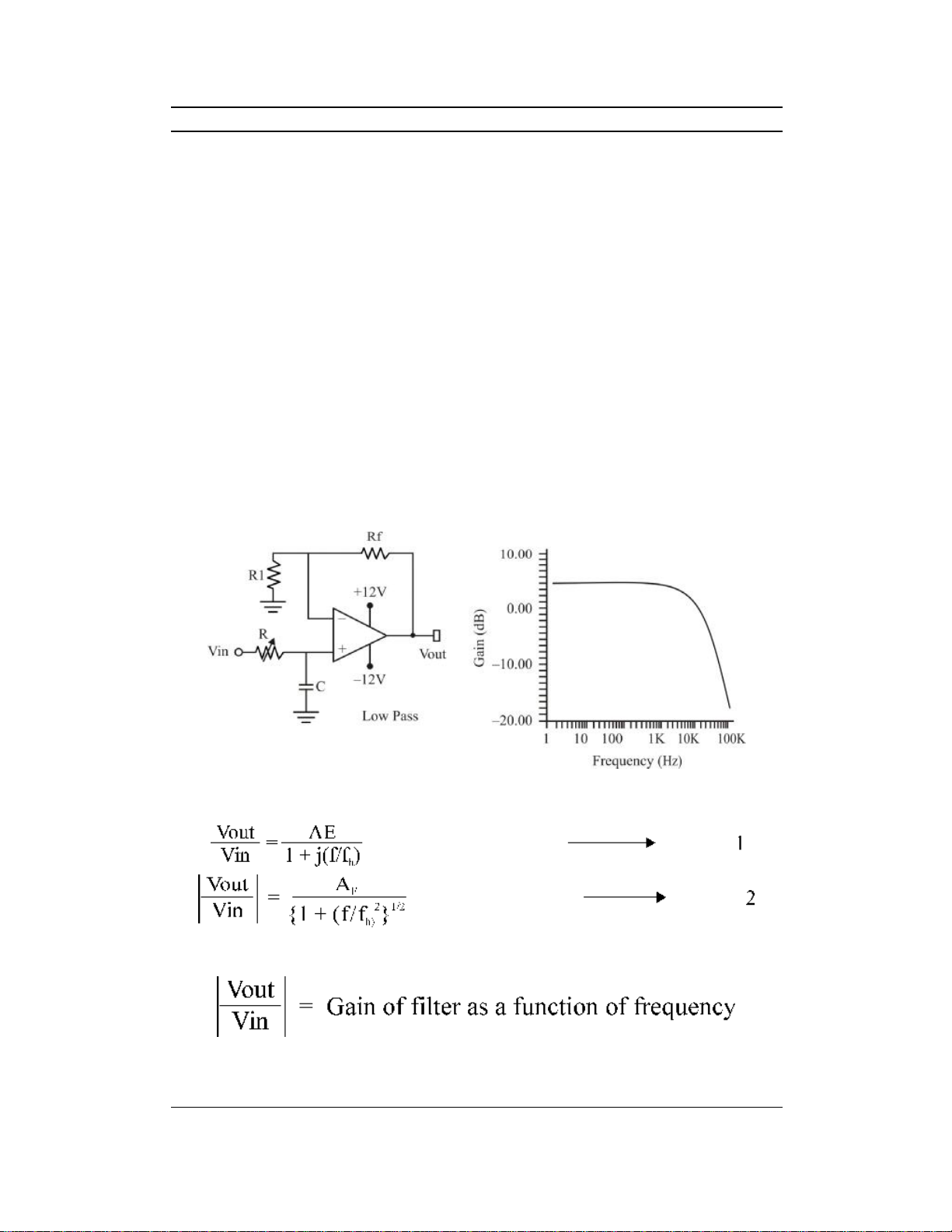
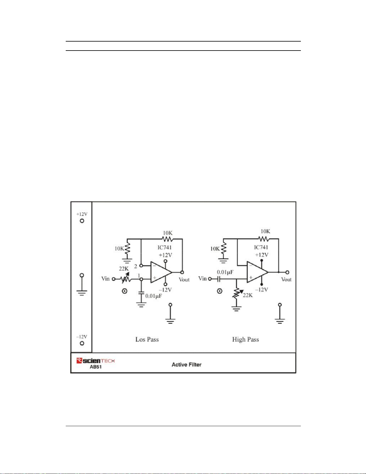
AB51 isacompact,readytouse ActiveFilters experimentboard.Itincorporates
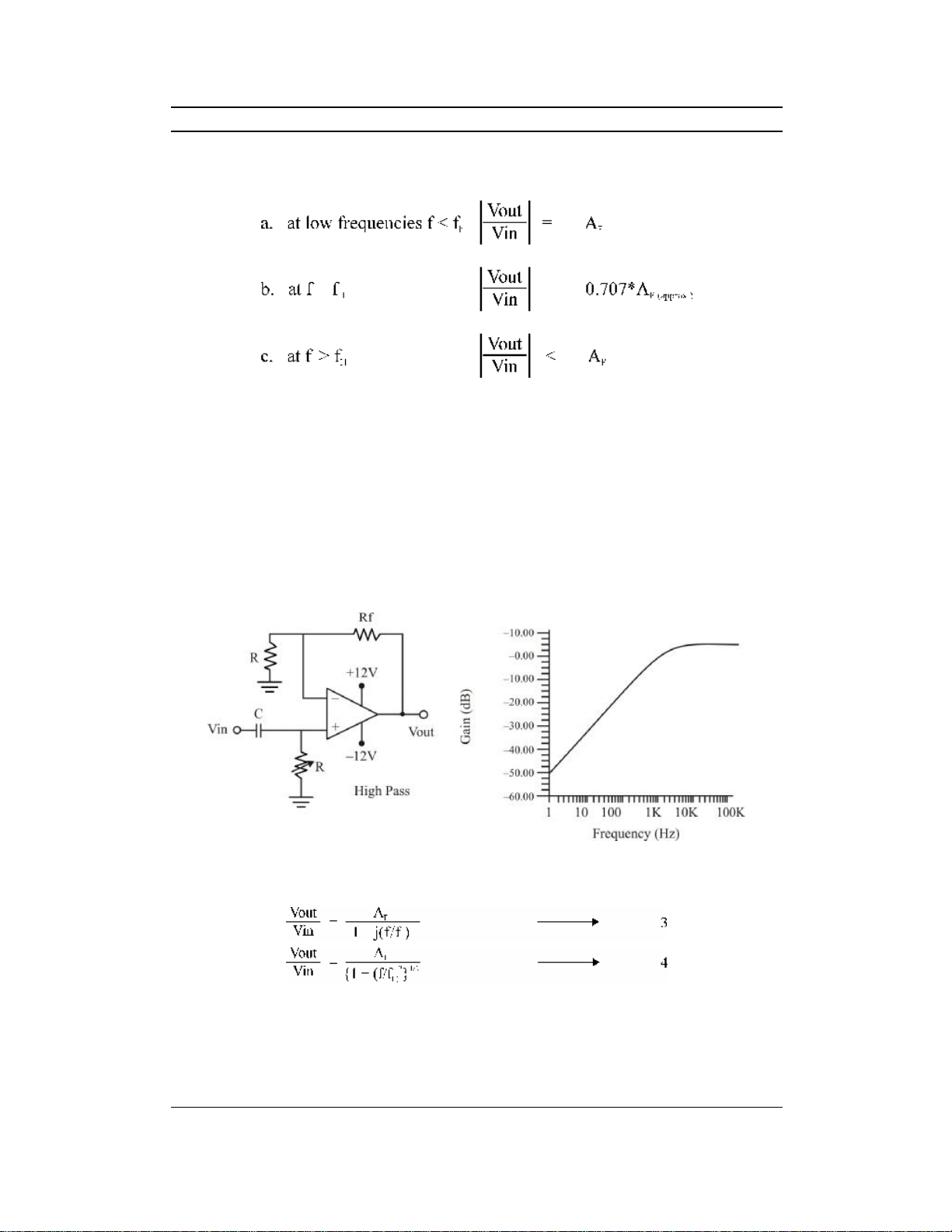
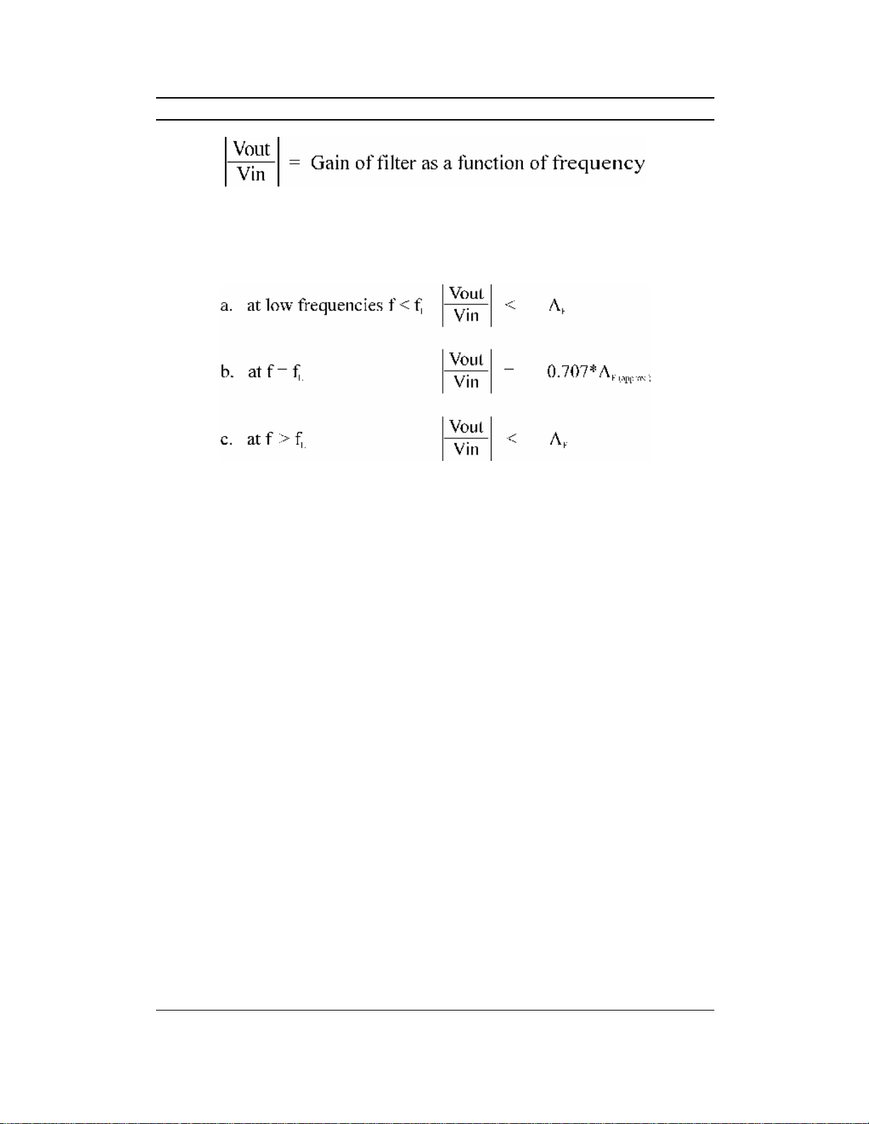
LowpassfilterandHigh pass filteronasingleboardandillustratesthefunctionality
ofActivefiltersatadjustablecutoff frequency.Itcanbeusedasstandaloneunitwith
externalpowersupplyorcanbeusedwith ScientechAnaloglabST2612 whichhas
builtinDCpowersupply,ACpowersupply,functiongenerator,modulation
generator, continuitytester, toggleswitchesandpotentiometers.
ListofBoards:
ModelName
AB01 Diodecharacteristics(Si, Zener,LED)
AB02 Transistorcharacteristics(CBNPN)
AB03 Transistorcharacteristics(CBPNP)
AB04 Transistorcharacteristics(CENPN)
AB05 Transistorcharacteristics(CE PNP)
AB06 Transistorcharacteristics(CCNPN)
AB07 Transistorcharacteristics(CCPNP)
AB08 FETcharacteristics
AB09 RectifierCircuits
AB10 WheatstoneBridge
AB11 Maxwell’sBridge
AB12 DeSauty’sBridge
AB13 Schering Bridge
AB15 CommonEmitterAmplifier
AB14 DarlingtonPair
AB16 CommonCollectorAmplifier
AB17 CommonBaseAmplifier
AB18 CascodeAmplifier
AB19 RC-CoupledAmplifier
AB20 DirectCoupledAmplifier
AB21 Class AAmplifier
AB22 Class BAmplifier(pushpullemitterfollower)
AB23 Class CTunedAmplifier
AB25 PhaseLockedLoop (FMDemodulator&FrequencyDivider/
Multiplier)
AB28 Multivibrator(Monostable/Astable)
AB29 F-VandV-FConverter
AB30 V-IandI-VConverter
AB31 ZenerVoltageRegulator
AB32 TransistorSeriesVoltageRegulator
AB33 TransistorShuntVoltageRegulator
AB35 DCAmmeter
AB39 InstrumentationAmplifier
AB41 DifferentialAmplifier(Transistorized)
AB42 OperationalAmplifier(Inverting /Non-inverting/Differentiator)

AB51
ScientechTechnologies Pvt.Ltd.5
AB43 OperationalAmplifier(Adder/Scalar)
AB44 OperationalAmplifier(Integrator/Differentiator)
AB45 Schmitt TriggerandComparator
AB49 KDerivedFilter
AB52 ActiveBandPass Filter
AB54 Tschebyscheff Filter
AB56 FiberOpticAnalogLink
AB57 Owen’sBridge
AB58 Anderson’sBridge
AB59 Maxwell’sInductance Bridge
AB64 RC –CoupledAmplifierwithFeedback
AB65 PhaseShiftOscillator
AB66 WienBridgeOscillators
AB67 Colpitt Oscillator
AB68 HartleyOscillator
AB80 RLCSeriesandRLCParallelResonance
AB82 Thevenin’sandMaximumpowerTransferTheorem
AB83 ReciprocityandSuperpositionTheorem
AB84 Tellegen’sTheorem
AB85 Norton’stheorem
AB88 DiodeClipper
AB89 DiodeClampers
AB90 Twoportnetworkparameter
AB91 OpticalTransducer(Photovoltaiccell)
AB92 OpticalTransducer(Photoconductivecell/LDR)
AB93 OpticalTransducer(Phototransistor)
AB96 TemperatureTransducer(RTD&IC335)
AB97 TemperatureTransducer(Thermocouple)
AB101 DSBModulatorandDemodulator
AB102 SSBModulatorandDemodulator
AB106 FMModulatorandDemodulator ………… andmanymore

AB51
ScientechTechnologies Pvt.Ltd.6
Theory
Anelectricfilterisafrequencyselectivecircuitthatpasseselectricsignalsofspecific
bandoffrequenciesandattenuatessignaloffrequenciesoutsidethisband.Depending
onthetypeofelementsusedintheirconstructionfiltersmaybeclassifiedaspassive
oractivefilters.Elementsusedinpassivefiltersareresistors,capacitorsand
inductors.ActivefilterconsistsofactivecomponentssuchasOp-amp,transistors
withpassiveelements.
Mostcommonlyusedfiltersare:
1. LowPass Filter
2. HighPassFilter
3. BandPass Filter
LowPass Filter:
Itisafrequencyselectivecircuit,whichpassessignalsoffrequencybelowit’shigh
cutoff frequency(fh)andattenuatessignalsoffrequencyabovefh.
Figure1
Equationoflowpass filteris
Vin=InputsignalVoltage
Vout=OutputsignalVoltage
AF=1+RF/R1=pass bandgainoffilter
f=frequencyofinputsignal

AB51
ScientechTechnologies Pvt.Ltd.7
fH=1/2πRC =highcutoff frequency, 3-db frequency,cornerfrequencyOperationof
lowpass filterusing equation2
Theideallowpass filterhasaconstantgainAFfrom0tohighcutoff frequency(fH)
atfHthegainis0.707*Af.AndafterfHit decreasesataconstantratewithanincrease
infrequencyi.e.wheninputfrequencyisincreasedtenfold(onedecade),thevoltage
gainisdividedby10.
Gain(db)=20log|Vout /Vin|
i.e.GainRoll off rateis −20db /decade.
HighPassFilter:
Itisafrequencyselectivecircuit,whichpassessignalsoffrequenciesaboveit'slow
cutoff frequency(fL)andattenuatessignalsoffrequenciesbelowfL.
Figure2
EquationofHighpassfilteris
Vin=InputsignalVoltage
Vout=OutputsignalVoltage

AB51
ScientechTechnologies Pvt.Ltd.8
AF=1+RF/R1=pass bandgainoffilter
f=frequencyofinputsignal
fL=1/2 πRC =Lowcutoff frequency,3-db frequency,cornerfrequencyOperation
ofhighpass filterusing equation.
Inidealhigh pass filter,whenf<fLgainisincreasedataconstantratehasaconstant
ratewithanincreaseinfrequency.At fLthegainis0.707*AF.AndabovefL
ithas
constantgainofAF. BelowfLwheninputfrequencyisincreasedtenfold(onedecade),
thevoltagegainismultipliedby10.
Gain(db)=20 log|Vout/Vin|
i.e.GainRoll off rateis −20db /decade.

AB51
ScientechTechnologies Pvt.Ltd.9
Experiment1
Objective:
StudyoftheActiveLowPass Filter andtoEvaluate:
•Highcutoff frequencyofLowpass filter.
•Pass bandgainofLowPass Filter.
•PlotthefrequencyresponseofLowPass Filter.
EquipmentsNeeded:
1. Analogboardof AB51.
2. DCpowersupplies+12V, −12Vfrom externalsource or ST2612Analog Lab.
3. Functiongeneratoror ST2612AnalogLab.
4. Oscilloscope
5. DigitalMultimeter
6. 2mmpatchcords.
Circuitdiagram:
Circuit usedtostudyActiveLowpass filtershowninfigure3.
Figure3

AB51
ScientechTechnologies Pvt.Ltd.10
Procedure :
1. ConnectOhmmeterbetweenTestpointVinandTestpoint1.Adjustresistance
valueto1.59Kbyvarying thepotentiometer22KofLowpass filtertosetthe
high cutoff frequency(fH)at10K.
2. Connect+12Vand −12VDCpowersuppliesattheirindicatedpositionfrom
externalsource or ST2612Analog Lab.
3. Switch‘On’thepowersupply.
4. Connectasinusoidalsignalofamplitude1V(p-p)offrequency1KHztoVinof
LowPass Filterfrom externalsourceor ST2612AnalogLab.
5. Observeoutputonoscilloscopebyconnecting TestpointVouttooscilloscope.
6. Increasethefrequencyofinputsignalstepbystepandobservetheeffecton
outputVoutonoscilloscope.
7. TabulatevaluesofVout,gain,gain(db)atdifferentvaluesofinputfrequency
showninobservationTable.
ObservationTable:
Sr.
No.
Input
frequency
(Hz) Vout |Vout/Vin|= gain
Gain(db)=20
Log |Vout/Vin|
1 500
2 1K
3 5K
4 10K(fH)
5 15K
6 20K
7 30K
8. Plotthefrequencyresponseoflowpassfilterusing thedataobtainedatdifferent
inputfrequencies.

AB51
ScientechTechnologies Pvt.Ltd.11
9. PerformthesameprocedureatdifferentCutoff frequenciesasshownbelow:
Resistance(Ω) Capacitance(uF) fHhighcutoff
frequency(Hz)
800 0.01 20K
1.59 K 0.01 10K
15.9K 0.01 1K
TheoreticalCalculations:
Calculateallthefollowingvalues
1. Pass bandgainofLowpass filterAF=1+RF /R1
2. Pass bandgain(db)=20 log|Vout/Vin|
3. 3dbfrequencyfH=1/2πRC
4. Gainat3dbfrequencyfH=0.707*AF
5. Gain(db)at3dbfrequencyfH=20log|Vout/Vin|where
Vout=(2)1/2 *Vin
6. Roll off rate= −20db/decade
Results:
Theoretical Practical
Pass bandgain(Af)
Passband gain(Af)indb
3dbfrequencyfH
Gainat3dbfrequency(fH)indb

AB51
ScientechTechnologies Pvt.Ltd.12
Experiment2
Objective:
StudyoftheActiveHighPass Filterand toEvaluate:
1. LowcutofffrequencyofLowpass filter.
2. Pass bandgainofHighpassfilter.
3. PlotthefrequencyresponseofHighpass filter.
EquipmentsNeeded:
1. Analogboardof AB51.
2. DCpowersupplies+12V, −12Vfrom externalsource or ST2612Analog Lab.
3. Functiongeneratoror ST2612AnalogLab.
4. Oscilloscope
5. DigitalMultimeter
6. 2mmpatchcords.
CircuitDiagram:
Circuit usedtostudyActiveHigh pass filtershowninfigure4.
Figure4

AB51
ScientechTechnologies Pvt.Ltd.13
Procedure :
1. ConnectOhmmeterbetweenVinandTestpoint3.Adjustresistancevalueto
15.9Kbyvarying thepotentiometer22KofHighpass filtertosettheLow
cutoff frequency(fL)at1K.
2. Connect+12Vand −12VDCpowersuppliesattheirindicatedpositionfrom
externalsource or ST2612Analog Lab.
3. Switch‘On’thepowersupply.
4. Connectasinusoidalsignalofamplitude1V(p-p)offrequency
100Hz totheTestpointVin ofhighpass filterfromexternalsourceor ST2612
AnalogLab.
5. Observeoutputonoscilloscopebyconnecting TestpointVouttooscilloscope.
6. Increasethefrequencyofinputsignalstepbystepandobservetheeffecton
outputVoutonoscilloscope.
7. TabulatedifferentvaluesofVout,gain,gain(db)atdifferentvaluesofinput
frequencyshowninobservationTable.
ObservationTable:
Sr.
No.
Input
frequency
(Hz) Vout |Vout/Vin|=gain Gain(db)=20
Log|Vout/Vin|
1 100
2 200
3 500
4 1K(fL)
5 5K
6 10K
7 15K
8 20K

AB51
ScientechTechnologies Pvt.Ltd.14
8. Plotthefrequencyresponseofhighpass filterusingthedataobtainedat
differentinputfrequencies.
9. PerformthesameprocedureatdifferentCutoff frequenciesasshownbelow:
Resistance(Ω) Capacitance (µF) 3db frequency(Hz)
800 0.01 20K
1.59 K 0.01 10K
15.9K 0.01 1K
TheoreticalCalculations:
Calculateallthefollowingvalues
1. Pass bandgainofLowpass filterAF=1+RF /R1
2. Pass bandgain(db)=20 log|Vout/Vin|
3. Lowcutoff frequencyfL=1/2πRC
4. GainatLowcutoff frequencyfL=0.707*AF
5. Gain(db)atLowcutoff frequencyfH=20 log|Vout/Vin|where
Vout=(2)1/2 *Vin
6. Roll off rate= −20db/decade
Results:
Theoretical Practical
Pass bandgain(Af)
Pass bandgain(Af)indb
Lowcutofffrequency(fL)
Gainat3dbfrequency(fL)indb

AB51
ScientechTechnologies Pvt.Ltd.15
DataSheet

AB51
ScientechTechnologies Pvt.Ltd.16
Warranty
1. Weguaranteetheproductagainstallmanufacturingdefectsfor24monthsfrom
thedateofsalebyusorthroughourdealers.Consumableslikedrycelletc.are
notcoveredunderwarranty.
2. Theguaranteewillbecomevoid,if
a) Theproductisnotoperatedaspertheinstructiongivenintheoperating
manual.
b) Theagreedpaymenttermsandotherconditionsofsalearenotfollowed.
c) Thecustomerresellstheinstrumenttoanotherparty.
d) Anyattemptismadetoserviceandmodifytheinstrument.
3. Thenon-workingoftheproductistobecommunicatedtousimmediatelygiving
full detailsofthecomplaintsanddefectsnoticedspecificallymentioningthe
type,serialnumberoftheproductanddateofpurchaseetc.
4. Therepairworkwillbecarriedout,providedtheproductisdispatchedsecurely
packedandinsured. Thetransportationchargesshallbebornebythecustomer.
ForanyTechnicalProblemPleaseContactusat service@scientech.bz
ListofAccessories
1. 2mm PatchCord(Red)16”................................................................2Nos.
2. 2mm PatchCord(Black)16”..............................................................2Nos.
3. 2mm PatchCord(Blue)16”...............................................................3Nos.
4. e-Manual..............................................................................................1No.
Updated26-06-2009
Table of contents
Popular Water Filtration System manuals by other brands

PTE
PTE Ecoflo STB-650B owner's manual

Trane Technologies
Trane Technologies BAYFLTR101C Installer's guide

Altecnic
Altecnic DirtmagIQ Quattro installation guide

amiad
amiad TEQUATIC PLUS F-150 C Series Installation, operation and maintenance manual

Emerald
Emerald Home 3 Passport and operation manual

Auga
Auga VarioPress Pro Series Operation instructions