Scientific Atlanta D9225 Operating instructions


If receiver setup details are unavailable, you can perform a Quick Setup of your
Headend Satellite Receiver by following the step-by-step instructions in this Quick
Setup Guide. After performing the Quick Setup, you can change the current set-
tings to better suit your receiver operating requirements. If you are unsure about
which settings to use, contact your dealer/reseller or local service provider for as-
sistance. For complete receiver setup information, see the Model D9225 Headend
Satellite Receiver Installation and Operation Guide.
«$ERXWWKH9LGHR6WDQGDUG
The Video Standard used to operate the receiver is preset at the factory to either
NTSC (525-line) or PAL (625-line), depending on factory-installed options.
5HFHLYHU6WDUWXS
Step 1. Check your installation:
(a)
Check that the receiver is correctly installed and connected to the
satellite LNB antenna, to other A/V equipment (as required) and to AC power.
(b)
Verify that the satellite LNB power switch at the receiver rear panel is
correctly set (OFF to use the external LNB power source, or ON to use the
internal receiver LNB power source).
Step 2. Power-on the receiver:
Press the STANDBY front panel button (1).
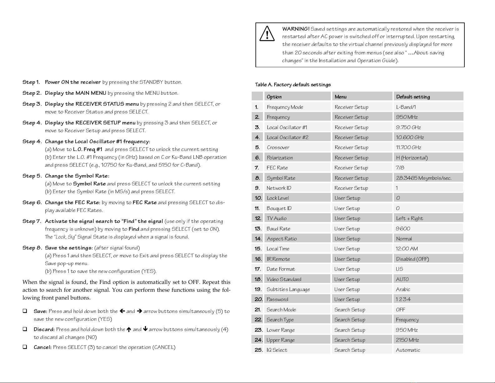
Step 3. Change the video standard [if required]:
(a)
Press and hold the SELECT button (3), then
(b)
Press the
Ï
arrow button
(4) once to replace the current setting.
(c)
Press the
Ï
arrow button again
(4) to select the alternate video standard.
To use the ON/STANDBY, MENU, SELECT and arrow buttons
(1) Press
STANDBY
....................................................................................................................................
STANDBY
(2) Press
MENU
............................................................................................................................................
MENU
(3) Press
SELECT
........................................................................................................................................
(4) Press
Ï
and
Ð
........................................................................................................................
(5) Press
Í
and
Î
......................................................................................................................
4XLFN6HWXS*XLGH
C/Ku FEC S.Q.
MODE
FREQ
SYM SIG
POL AFC
VIEWALT
123
456
789
0
Alt-1 Mode Alt-2 Mode
BAUD LO 1 LOCK
LO 2 WIDE
XOVER
VIEWALT
123
456
789
0
SEARCH
IMPORTANT:
Only preauthorized subscriber services can be made available
for your Headend Satellite Receiver. If a unauthorized signal is present, a
warning message displays on the TV monitor. In this case, contact your
dealer/reseller or local service provider about satellite broadcast services
authorization.
Figure B. Front panel Alt-1 and Alt-2 Mode function buttons
IMPORTANT!
The current Video Standard setting is used by the receiver
for correct display of the video (picture) only. The satellite receiver does not
convert from one Video Standard to another, such as from NTSC (525-line)
to PAL-B (625-line).
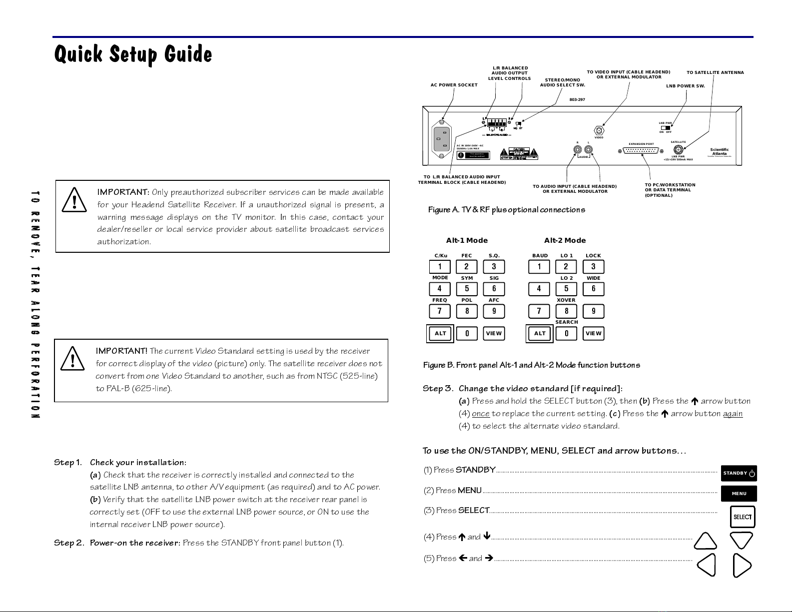
LNB POWER SW.
TO PC/WORKSTATION
OR DATA TERMINAL
(OPTIONAL)
TO SATELLITE ANTENNA
STEREO/MONO
AUDIO SELECT SW.AC POWER SOCKET
TO L/R BALANCED AUDIO INPUT
TERMINAL BLOCK (CABLE HEADEND)
L/R BALANCED
AUDIO OUTPUT
LEVEL CONTROLS TO VIDEO INPUT (CABLE HEADEND)
OR EXTERNAL MODULATOR
TO AUDIO INPUT (CABLE HEADEND)
OR EXTERNAL MODULATOR
803-297
Scientific
Atlanta
Satellite Television Networks
SATELLITE
LNB PWR
+13/+19V 500mA MAX
AC IN 100V-240V ~AC
50/60Hz 1.4A MAX
AUDIO
RL EXPANSION PORT
VIDEO
ON OFF
LNB PWR
This apparatus
mustbe earthed
Figure A. TV & RF plus optional connections
4XLFN6HWXSLQVWUXFWLRQV
Follow these quick setup instructions to set up the receiver via the menu interface
using front panel buttons, and to find a signal using the built-in signal search
function. To operate the menu interface, a RF cable must be connected from the
receiver VIDEO output to a TV monitor UHF/VHF RF input (see Figure A).
Step 1. Power ON the receiver
by pressing the STANDBY button.
Step 2. Display the MAIN MENU
by pressing the MENU button.
Step 3. Display the RECEIVER STATUS menu
by pressing 2 and then SELECT, or
move to Receiver Status and press SELECT.
Step 4. Display the RECEIVER SETUP menu
by pressing 3 and then SELECT, or
move to Receiver Setup and press SELECT.
Step 4. Change the Local Oscillator #1 frequency:
(a) Move to
L.O.Freq#1
and press SELECT to unlock the current setting
(b) Enter the L.O. #1 Frequency (in GHz) based on C or Ku-Band LNB operation
and press SELECT (e.g., 10750 for Ku-Band, and 5150 for C-Band).
Step 5. Change the Symbol Rate:
(a) Move to
Symbol Rate
and press SELECT to unlock the current setting
(b) Enter the Symbol Rate (in MS/s) and press SELECT.
Step 6. Change the FEC Rate:
by moving to
FEC Rate
and pressing SELECT to dis-
play available FEC Rates.
Step 7. Activate the signal search to Find the signal
(use only if the operating
frequency is unknown) by moving to
Find
and pressing SELECT (set to ON).
The
Lock, Sig
Signal State is displayed when a signal is found.
Step 8. Save the settings:
(after signal found)
(a) Press 1 and then SELECT, or move to Exit and press SELECT to display the
Save pop-up menu.
(b) Press 1 to save the new configuration (YES).
When the signal is found, the Find option is automatically set to OFF. Repeat this
action to search for another signal. You can perform these functions using the fol-
lowing front panel buttons.
Save:
Press and hold down both the
Í
and
Î
arrow buttons simultaneously (5) to
save the new configuration (YES)
Discard:
Press and hold down both the
Ï
and
Ð
arrow buttons simultaneously (4)
to discard all changes (NO)
Cancel:
Press SELECT (3) to cancel the operation (CANCEL)
Table A. Factory default settings
Option Menu Defaultsetting
1.
Frequency Mode Receiver Setup L-Band/1
2.
Frequency Receiver Setup 950 MHz
3.
Local Oscillator #1 Receiver Setup 9.750 GHz
4.
Local Oscillator #2 Receiver Setup 10.600 GHz
5.
Crossover Receiver Setup 11.700 GHz
6.
Polarization Receiver Setup H (Horizontal)
7.
FEC Rate Receiver Setup 7/8
8.
Symbol Rate Receiver Setup 28.3465 Msymbols/sec.
9.
Network ID Receiver Setup 1
10.
Lock Level User Setup 0
11.
Bouquet ID User Setup 0
12.
TV Audio User Setup Left + Right
13.
Baud Rate User Setup 9600
14.
Aspect Ratio User Setup Normal
15.
Local Time User Setup 12:00 AM
16.
IR Remote User Setup Disabled (OFF)
17.
Date Format User Setup US
18.
Video Standard User Setup AUTO
19.
Subtitles Language User Setup Arabic
20.
Password User Setup 1234
21.
Search Mode Search Setup OFF
22.
Search Type Search Setup Frequency
23.
Lower Range Search Setup 950 MHz
24.
Upper Range Search Setup 2150 MHz
25.
IQ Select Search Setup Automatic
WARNING!
Saved settings are automatically restored when the receiver is
restarted after AC power is switched off or interrupted. Upon restarting,
the receiver defaults to the virtual channel previously displayed for more
than 20 seconds after exiting from menus (see also
…
About saving
changes in the Installation and Operation Guide).
L
L
,03257$176$)(*8$5'6
Read Instructions: All the safety and operating instructions should be read before
this product is operated.
1. Retain Instructions: The safety and operating instructions should be retained
for future reference.
2. Heed Warnings: All warnings on the product and in the operating instructions
should be adhered to.
3. Follow Instructions: All operating and use instructions should be followed.
4. Cleaning: Unplug this product from the wall outlet before cleaning. Do not use
liquid cleaners or aerosol cleaners. Use a damp cloth for cleaning.
5. Attachments: Do not use attachments not recommended by Scientific-Atlanta as
they may cause hazards.
6. Water and Moisture: Do not use this product near water - for example, near a
bath tub, wash bowl, kitchen sink, or laundry tub, in a wet basement, or near a
swimming pool, and the like.
7. Accessories: Do not place this product on an unstable cart, stand, bracket, or
table. The product may fall causing serious injury to a child or adult, and
serious damage to the product. Use only with a cart, stand, bracket, or table
recommended by Scientific-Atlanta. Any mounting of the product should
follow the instructions, and should use a mounting accessory recommended by
Scientific-Atlanta.
An appliance and cart combination should be moved with care. Quick stops,
excessive force, and uneven surfaces may cause the appliance and cart
combination to overturn.
8. Ventilation: Slots and openings in the cabinet are provided for ventilation and
to ensure reliable operation of the product, and to protect it from overheating.
These openings must not be blocked or covered. The openings should never be
blocked by placing the product on a bed, sofa, rug, or other similar surface. This
product should not be placed in a built-in installation such as a bookcase or rack
unless proper ventilation is provided or the instructions have been adhered to.
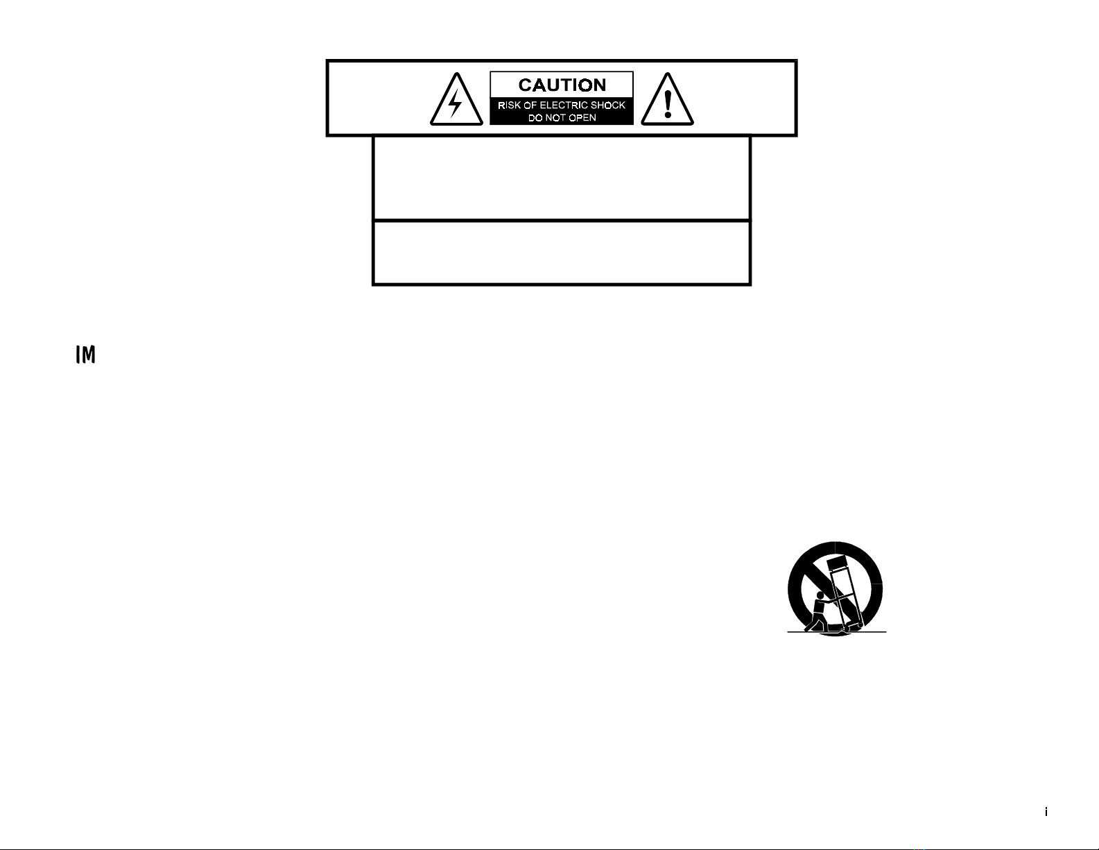
CAUTION
WARNING
TO REDUCE THE RISK OF ELECTRICAL SHOCK, DO NOT EXPOSE
THIS PRODUCT TO RAIN OR MOISTURE.
This symbol alerts you to
the presence of uninsulated
dangerous voltage inside
the product enclosure that
poses a risk of electric shock.
This symbol alerts you to
important operating and
maintenance (servicing)
instructions included
with this product.
TO REDUCE THE RISK OF ELECTRICAL SHOCK, DO NOT REMOVE
COVERS FROM THIS UNIT. NO USER-SERVICEABLE PARTS INSIDE.
REFER SERVICING TO QUALIFIED PERSONNEL. SEE ADDITIONAL
SAFETY INSTRUCTIONS BELOW.
PORTABLE CART WARNING

LL
LL
9. Heat: This product should be located away from heat sources such as radiators,
heat registers, stoves or other products (including amplifiers) that radiate heat.
10. Power Sources: This product should be operated only from the type of power
source indicated on the marking label. If you are not sure of the type of power
supply in your home or business, consult your appliance dealer or local power
company. For products intended to operate from battery power, or other
sources, refer to the operating instructions supplied with the product.
For applications other than in North America, a suitable attachment plug
adapter should be used for connection to the power source. For determining the
appropriate attachment adapter type, refer to qualified technical personnel.
11. Polarization: This product may be equipped with a polarized alternating cur-
rent line plug (i.e., a plug having one blade wider than the other). This plug will
fit into the power outlet only one way. This is a safety feature. If you are unable
to insert the plug fully into the outlet, try reversing the plug. If the plug should
still fail to fit, contact your electrician to replace your obsolete outlet. Do not de-
feat the safety purpose of the polarized plug.
12. Power Cord Protection: Power-supply cords should be routed so that they are
not likely to be walked on or pinched by items placed upon or against them,
paying particular attention to cords at plugs, convenience receptacles, and the
point where they exit from the appliance.
13. Lightning: For added protection for this product during a lightning storm or
when it is left unattended and unused for long periods of time, unplug it from
the wall outlet and disconnect the antenna or cable system. This will prevent
damage to the product due to lightning and power-line surges.
14. Power Lines: An outside antenna system should not be located in the vicinity of
overhead power lines or other electric light or power circuits, or where it can
fall into such power or circuits. When installing an outside antenna system, ex-
treme care should be taken to keep from touching such power lines or circuits as
contact with them might be fatal.
15. Overloading: Do not overload wall outlets, extension cords or integral conven-
ience receptacles, as this can result in a risk of fire or electric shock.
16. Object and Liquid Entry: Never push objects of any kind into this product
through openings as they may touch dangerous voltage points or short-out
parts that could result in a fire or electric shock. Never spill liquid of any kind
on the product.
17. Servicing: Do not attempt to service this product yourself as opening or re-
moving covers may expose you to dangerous voltage or other hazards. Refer all
servicing to qualified service personnel.
18. Damage Requiring Service: Unplug this product from the wall outlet and refer
servicing to qualified service personnel under the following conditions:
(a) When the power-supply cord or plug is damaged.
(b) If liquid has been spilled, or objects have fallen into the product.
(c) If the product has been exposed to rain or water.
(d) If the product does not operate normally by following the operating instruc-
tions. Adjust only those controls that are covered by the operating instructions
as an improper adjustment of other controls may result in damage and will of-
ten require extensive work by a qualified technician to restore the product to its
normal operation.
(e) If the product has been dropped or damaged in any way.
(f) The product exhibits a distinct change in performance.
19. Replacement Parts: When replacement parts are required, be sure the service
technician uses replacement parts specified by Scientific-Atlanta, or parts hav-
ing the same operating characteristics as the original parts. Unauthorized part
substitutions made may result in fire, electric shock or other hazards.
20. Safety Check: Upon completion of any service or repairs made to this product,
ask the service technician to perform safety checks to determine that the product
is in safe operating condition.
21. Outdoor Antenna Grounding: If an outside antenna or cable system is con-
nected to this product, ensure that the antenna or cable system is properly
grounded to provide protection against voltage surges and built-up static
charges. Appropriate sections of the National Electrical Code (NFPA 1990) pro-
vide information with respect to proper grounding of the mast and supporting
structure, grounding of the lead-in wire to an antenna discharge unit, connec-
tion to grounding electrodes, and requirements for the grounding electrode (see
“…About receiver & satellite antenna grounding”).

LLL
LLL
«$ERXWUHFHLYHUVDWHOOLWHDQWHQQDJURXQGLQJ
Before you can operate your Headend Satellite Receiver system, both the receiver
chassis and the satellite antenna LNB connection(s) must be properly grounded.
Information about grounding your receiver and satellite antenna follow.
*URXQGLQJWKHUHFHLYHU
The receiver ground connection is made from the shield1conductor attached to the
RF coaxial cable “F” connector (rear panel SATELLITE input) to an external
grounding rod via a receiver/antenna grounding block. A separate grounding
wire connects the grounding block (and the satellite antenna LNB grounding
block) to the grounding rod (see Figure 1).
*URXQGLQJWKH/1%DQGRU9+)8+)DQWHQQD
The antenna ground connection is made from the satellite LNB/antenna ground
and/or the VHF/UHF terrestrial antenna discharge unit to an external grounding
rod via a receiver/antenna grounding block.
*HQHUDOJURXQGLQJLQIRUPDWLRQ
The actual ground/cable connections made depend on your site installation re-
quirements, and on the type of satellite antenna and/or VHF/UHF terrestrial an-
tenna you have. If your satellite antenna installation includes a dual-port LNB,
both RF coaxial cables must be routed to the grounding block. When connecting RF
coaxial antenna cables to the grounding block, looping the antenna cables as
shown in the accompanying figure helps to direct moisture away from the
grounding block. Always choose the shortest route possible when connecting RF
coaxial cables to the receiver/antenna grounding block, and when connecting the
grounding wire(s) to the grounding rod.
1Multi-strand (braided) shield that surrounds the center conductor of the coaxial
cable
Ensure that all wires/cables are properly routed, and are clamped/secured, as
required. Install the grounding rod as close to the grounding block as possible
(NEC 820-40 [USA]). If your satellite antenna is installed on a separate support
structure and/or is not located near the RF antenna cable point-of-entry, a dupli-
cate ground using a second grounding rod installed as close to the antenna as pos-
sible is recommended. Typically, a good earth ground can be obtained by driving a
grounding rod made of copper-clad iron into the ground next to the grounding
block.
$17(11$ /($',1 :,5(
*5281'
&/$03
$17(11$ ',6&+$5*( 81,7
1(& 6(&7,21
*5281',1* &21'8&7256
1(& 6(&7,21
(/(&75,&
6(59,&(
(48,30(17
*5281' &/$036
32:(5 6(59,&( *5281',1*
(/(&752'( 6<67(0
1(& $57 3$57 +
72 &$79 6<67(0 ,167$//(5
7KLV UHPLQGHU LV SURYLGHG WR FDOO WKH &$79 V\VWHP LQVWDOOHUV DWWHQWLRQ WR $UWLFOH RI WKH
1DWLRQDO (OHFWULFDO &RGH 1(& WKDW SURYLGHV JXLGHOLQHV IRU SURSHU JURXQGLQJ DQG LQ SDUWLFXODU
VSHFLILHV WKDW WKH FDEOH JURXQG VKDOO EH FRQQHFWHG WR WKH JURXQGLQJ V\VWHP RI WKH EXLOGLQJ
DV FORVH WR WKH SRLQW RI HQWU\ DV SUDFWLFDO
1(& 1$7,21$/ (/(&75,&$/ &2'(
1$7,21$/ ),5( 3527(&7,21 $662&,$7,21
Figure1. Receiver& satellite antenna grounding

LY
LY
$&0$,16/($'&211(&7,21,03257$17
The wires in this mains lead are coloured in accordance with the following code:
Green-and-Yellow: Earth
Blue: Neutral
Brown: Live
As the colours of the wires in the mains lead of this apparatus may not correspond
with coloured markings identifying the terminal in your plug, proceed as follows:
1.
The wire which is coloured green-and-yellow must be connected to the terminal plug
which is marked by the letter E, by the safety earth symbol ( )or coloured green-
and-yellow.
2.
The wire which is coloured blue must be connected to the terminal which is marked
with the letter N or coloured black.
3.
The wire which is coloured brown must be connected to the terminal which is marked
with the letter L or coloured red.
:$51,1*
To prevent fire or electric shock:
Do not expose this apparatus to rain or moisture.
Avoid spilling liquids on or near this apparatus.
Do not open the top cover of this apparatus.
Do not push objects through openings in this apparatus.
Refer servicing to qualified personnel only. Contact your cable operator for service.
$77(17,21
Afin d'éviter tout incendie ou choc électrique:
Ne laissez pas cet appareil sous la pluie ou dans un endroit humide.
Ne renversez pas de liquide sur ou à proximité de l'appareil.
N'ouvrez pas le couvercle supérieur de l'appareil.
N'insérez pas d'objet dans les ouvertures de l'appareil.
Faites réparer votre appareil par une personne qualifiée, contactez votre opérateur
cable pour le service
6$)(7<35(&$87,216(80DUNHW
0(685(6'(6e&85,7e
6,&+(5+(,760$661$+0(1
35(&$8&,21(6'(6(*85,'$'
NOTICE FOR CUSTOMERS
IN THE UNITED KINGDOM
WARNING
THIS APPARATUS MUST BE EARTHED
IMPORTANT
Install this product on a flat surface only, ensuring that
all four rubber feet are making full contact with the
mounting surface. During normal operation, it is
recommended that physical contact be limited to using
the front panel buttons only. Do not place any other
equipment directly on top of the receiver, and prevent
foreign objects from coming into direct contact with the
chassis. Subjecting this product to abnormal impact
may result in momentary interruption of video service.

Y
Y
:$5181*
Um Feuer oder elektrischen Schock zu vermeiden:
Keiner Nässe oder Feuchtigkeit aussetzen.
Keine Flüssigkeiten auf oder in der Nähe des Gerätes verschütten.
Den oberen Deckel nicht öffnen.
Keine Gegenstande in die Geräteöffnungen stecken.
Arbeiten am Gerät nur von qualifiziertem Personal vornehmen lassen. Wenden sie
sich an ihre Kabelfirma.
$'9(57(1&,$
Para prevenir incendio o una descarga electrica:
No exponga este aparato a la lluviaoalahumedad.
Evite derramar liquidos en o cerca del aparato.
No abra la cubierta superior de este aparato.
No introduzca objetos a traves de las aberturas de este aparato.
Mandelo a servicio unicamente donde existe personal calificado. Para servicio con-
sulte con su operador de cable.
&$87,21
To protect this apparatus against damage from lightning storms and power-line
surges, or when you are not using this apparatus for a long period of time, discon-
nect the power cord from the AC outlet.
To disconnect the cord, pull it out by grasping the plug. Never pull the cord itself.
Additionally, never walk on, place objects on, or pinch the power cord.
The top cover on this apparatus has openings for ventilation to protect it from
overheating. To ensure reliable operation, do not block or cover these openings by
placing this apparatus on a bed, sofa, rug, or any similar surface, or by placing en-
tertainment apparatus, lamps, books, or other objects on the top cover.
Additionally, never place this apparatus near or over a radiator or heat register, or
a built-in installation, such as a bookcase or rack, unless the installation provides
proper ventilation.
Locate this apparatus on a stable, vibration-free surface capable of supporting its
weight and size.
35e&$87,21635(1'5(
Afin de protéger votre appareil des orages et des surtensions de courant ou si vous
ne l'utilisez pas pendant une période prolongée, débranchez de la prise électrique du
secteur.
Pour débrancher, tirez sur la prise. Ne tirez jamais sur le cordon secteur. En outre,
ne marchez jamais sur le cordon, ne placez pas d'objet dessus et ne le coincez pas.
Le couvercle supérieur de cet appareil comprend des ouvertures pour la ventilation
afin d'éviter qu'il ne chauffe trop. Pour assurer un bon fonctionnement, ne bloquez
pas ou ne couvrez pas ces ouvertures en plaçant cet appareil sur un lit, un sofa, un
tapis ou toute autre surface sembiable. Ne posez pas de lampes, livres ou tout
autre objet sur le couvercle supérieur.
De plus, il ne faut jamais mettre cet appareil près d'un radiateur ou tout autre
élément dégageant de la chaleur. Ne l'incorporez pas dans une installation comme
une bibliothèque, une étagére, à moins que l'installation offre une ventilation appro-
priée.
Installez cet appareil sur une surface dégagée, stable et sans vibration capable de
supporter son poids et sa taille.
9256,&+7
Um dieses Gerät vor Biltzschlag bzw. Stromüberladung zu schützen, oder wenn das
Gerät längere Zeit nicht benutzt wird, soll der Stecker aus der Steckdose gezogen
werden.
Zum Abschalten immer am Stecker selbst und nie am Kabel ziehen. Außerdem nie
darauf treten, einen Gegenstand darauf legen oder das Kabel drücken.
YL
YL
Die Oberseite des Gerätes hat Ventilationsöffnungen, die das Gerät vor Über-
hitzung schützen. Um einwandfreies Funktionieren zu gewährleisten, dürfen diese
Öffnungen nicht blockiert oder verdeckt werden (z.B. nicht auf ein Bett, Sofa, Tep-
pich oder ähnliche Unterlagen stellen, oder Lampen, Bücher oder ähnliches auf das
Gerät stellen).
Außerdem soll dieses Gerät nie in der Nähe einer Heizquelle stehen. Vermeiden Sie,
das Gerät in einem geschlossenen Platz aufzustellen, z. B. Schrank, wo ausreich-
ende Ventilation nicht möglich ist.
Stellen Sie das Gerät auf eine stabile und schwingungsfreie Unterlage, die für das
Gerät groß genug ist.
35(&$8&,21
Para proteger este aparato contra daños producidos port tormentas eléctricas y
pulsaciones de energia eléctrica, o cuando no use este aparato por largo tiempo,
desconéctelo del tomacorriente de CA.
Para desconectar el cable, tómelo del enchufe y desconéctelo. Nunca tire del cable
directamente. Asimismo, nunca apriete, pise, o coloque objetos sobre el cable.
La cubierta superior de este aparato tiene aberturas de ventilación para evitar que
se recaliente. Para asegurar una operación confiable, no bloquee o cubra estas aber-
turas colocando este aparato sobre una cama, sofá, alfombra o cualquier superficle
similar, o colocando sobre la cubierta superior artefactos de entretenimiento, lám-
paras, libros u otros objetos.
Adicionalmente, nunca coloque este aparato cerca o sobre una salida de calefacción
o lo instale en un lugar tal como un mueble integrado o estante para libros, a menos
que la instalación proporcione una ventilación adecuada.
Coloque este aparato sobre una superficle estable, sin vibraciones y que tenga la
capacidad de aguantar su peso y tamaño.

YLL
YLL
9=@?BD1>D C1657E1B4CY
ª1R_ed bUSUYfUb cQdU\\YdU Q^dU^^Q Wb_e^TY^W YYY
7b_e^TY^W dXU bUSUYfUbYYY
7b_e^TY^W dXU <>2 Q^T_b F86E86 Q^dU^^Q YYY
7U^UbQ\ Wb_e^TY^W Y^V_b]QdY_^YYY
C165DI @B531ED9?>C 5E =Qb[UdYf
9^db_TeSdY_^
9^db_TeSdY_^
!
!
ª
ª
1R_ed dXYc WeYTU!
I_eb 8UQTU^T CQdU\\YdU BUSUYfUb !
E^`QS[Y^W i_eb bUSUYfUb!
2UV_bU i_e WUd cdQbdUT!
3_^^USdY^W i_eb cicdU] "
…
1R_ed dXU 5H@1>C9?> `_bd "
DF B6 `\ec _`dY_^Q\ S_^^USdY_^c#
?`U
?`Ub
bQdY^W dXU
QdY^W dXU b
bUSUY
USUYf
fUb
Ub
$
$
6b_^d `Q^U\ S_^db_\c TYc`\Qi $
CD1>42I Redd_^ $
=5>E Redd_^ $
C97>1< Y^TYSQd_b <54 $
1<D =_TU Y^TYSQd_b <54 $
'CUW]U^d TYc`\Qi$
=
E<D9
6
E>3D9?>
[Ui`QT%
>
E=5B93
[Ui`QT%
C
=1BD
3
1B4
c\_d %
3
81>79>7
SXQ^^U\c%
3
81>79>7
dXU f_\e]U %
=U^ec QdQW\Q^SU &
CUddY^W e` dXU
CUddY^W e` dXU b
bUSUY
USUYf
fUb
Ub
'
'
…
1R_ed dXU 1\dUb^QdU =_TU Y^dUbVQSU'
…
1R_ed _`UbQdY^W dXU _^cSbUU^ ]U^ec'
…
1R_ed U^dUbY^W ^e]RUbc ecY^W Vb_^d `Q^U\ Redd_^c(
…
1R_ed cQfY^W SXQ^WUc(
ª1R_ed dXU SebbU^d SXQ^^U\)
…
1R_ed SXQ^WY^W dXU FYTU_ CdQ^TQbT)
…
1R_ed dXU >Udg_b[ 94!
…
1R_ed dXU @Qccg_bT!
…
1R_ed <_S[ <UfU\c!
…
1R_ed CYW^Q\ CUQbSXUc !!
1\d =_TU _`U
1\d =_TU _`Ub
bQdY_^
QdY_^
!"
!"
…
1R_ed 1\d =_TUc !"
ª1R_ed VbUaeU^Si cUddY^Wc!#
ª1R_ed SXQ^WY^W dXU Ci]R_\ BQdU!$
163 <UfU\!%
1\d! =_TU!%
1\d" =_TU !%
1c`USd BQdY_!%
2QeT BQdU!&
653 BQdU!&
2Q^T CU\USd!&
3b_cc_fUb VbUaeU^Si!'
6QSd_bi BUcUd !'
6bUaeU^Si !'
6bUaeU^Si =_TU!(
<_S[ <UfU\ !(
<? 6bUaeU^Si !!)
<? 6bUaeU^Si " !)
CYW^Q\ AeQ\Ydi"
CYW^Q\ @_\QbYjQdY_^"
CYW^Q\ CUQbSX"
CYW^Q\ CdbU^WdX"!
Ci]R_\ BQdU"!
FYUg""
?^cS
?^cSb
bUU^ ]U^e _`U
UU^ ]U^e _`Ub
bQdY_^
QdY_^
"#
"#
…
1R_ed _^cSbUU^ ]U^e _`UbQdY_^"#
BUSUYfUb CUde` ]U^e"$
ª1R_ed VbUaeU^Si cUddY^Wc"$
ª
ª
1R_ed dXU CYW^Q\ CdQdU"'
ª
ª
1R_ed dXU 6Y^T _`dY_^ "'
EcUb CUde` ]U^e")
…
1R_ed <_S[ <UfU\c")
ª1R_ed dXU 1c`USd BQdY_ #
ª1R_ed dXU \_SQ\ dY]U #
ª1R_ed fYTU_ ceRdYd\Uc#!
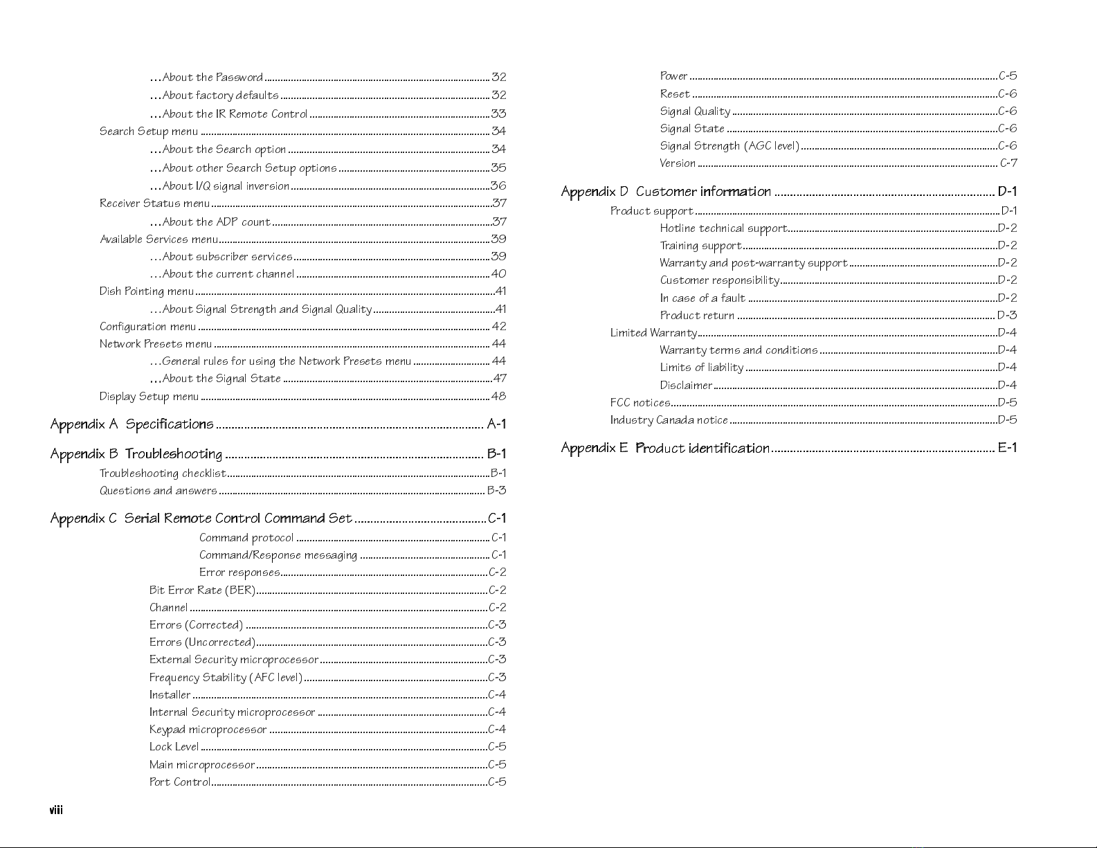
7DEOHRIFRQWHQWV
YLLL
YLLL
…
1R_ed dXU @Qccg_bT #"
…
1R_ed VQSd_bi TUVQe\dc#"
…
1R_ed dXU 9B BU]_dU 3_^db_\##
CUQbSX CUde` ]U^e#$
…
1R_ed dXU CUQbSX _`dY_^#$
…
1R_ed _dXUb CUQbSX CUde` _`dY_^c#%
…
1R_ed 9A cYW^Q\ Y^fUbcY_^#&
BUSUYfUb CdQdec ]U^e#'
…
1R_ed dXU 14@ S_e^d#'
1fQY\QR\U CUbfYSUc ]U^e#)
ª1R_ed ceRcSbYRUb cUbfYSUc#)
ª1R_ed dXU SebbU^d SXQ^^U\$
4YcX @_Y^dY^W ]U^e$!
ª1R_ed CYW^Q\ CdbU^WdX Q^T CYW^Q\ AeQ\Ydi$!
3_^VYWebQdY_^ ]U^e $"
>Udg_b[ @bUcUdc ]U^e $$
ª7U^UbQ\ be\Uc V_b ecY^W dXU >Udg_b[ @bUcUdc ]U^e $$
ª
ª
1R_ed dXU CYW^Q\ CdQdU$'
4Yc`\Qi CUde` ]U^e$(
1``U^TYh 1 C`USYVYSQdY_^c
1``U^TYh 1 C`USYVYSQdY_^c
1
1!
!
1``U^TYh 2
1``U^TYh 2 D
Db_eR\UcX__dY^W
b_eR\UcX__dY^W
2
2!
!
Db_eR\UcX__dY^W SXUS[\Ycd2!
AeUcdY_^c Q^T Q^cgUbc 2#
1``U^TYh 3 CUbYQ\ BU]_dU 3_^db_\ 3_]]Q^T CUd
1``U^TYh 3 CUbYQ\ BU]_dU 3_^db_\ 3_]]Q^T CUd
3
3!
!
3_]]Q^T `b_d_S_\ 3!
3_]]Q^TBUc`_^cU ]UccQWY^W3!
5bb_b bUc`_^cUc3"
2Yd 5bb_b BQdU 25B3"
3XQ^^U\3"
5bb_bc 3_bbUSdUT 3#
5bb_bc E^S_bbUSdUT3#
5hdUb^Q\ CUSebYdi ]YSb_`b_SUcc_b3#
6bUaeU^Si CdQRY\Ydi 163 \UfU\3#
9^cdQ\\Ub3$
9^dUb^Q\ CUSebYdi ]YSb_`b_SUcc_b3$
;Ui`QT ]YSb_`b_SUcc_b 3$
<_S[ <UfU\3%
=QY^ ]YSb_`b_SUcc_b3%
@_bd 3_^db_\3%
@_gUb3%
BUcUd 3&
CYW^Q\ AeQ\Ydi3&
CYW^Q\ CdQdU3&
CYW^Q\ CdbU^WdX 173 \UfU\3&
FUbcY_^ 3'
1``U^TYh 4 3ecd_]Ub Y^V_b]QdY_^
1``U^TYh 4 3ecd_]Ub Y^V_b]QdY_^
4
4!
!
@b_TeSd ce``_bd4!
8_d\Y^U dUSX^YSQ\ ce``_bd4"
DbQY^Y^W ce``_bd4"
GQbbQ^di Q^T `_cdgQbbQ^di ce``_bd4"
3ecd_]Ub bUc`_^cYRY\Ydi4"
9^ SQcU _V Q VQe\d 4"
@b_TeSd bUdeb^ 4#
<Y]YdUT GQbbQ^di4$
GQbbQ^di dUb]c Q^T S_^TYdY_^c4$
<Y]Ydc _V \YQRY\Ydi4$
4YcS\QY]Ub4$
633 ^_dYSUc4%
9^Tecdbi 3Q^QTQ ^_dYSU4%
1``U^TYh 5
1``U^TYh 5 @
@b_TeSd YTU^dYVYSQdY_^
b_TeSd YTU^dYVYSQdY_^
5
5!
!
«$ERXWWKLVJXLGH
This Installation and Operation Guide includes all the information you’ll need to
install and begin using your Scientific-Atlanta PowerVu Headend Satellite Re-
ceiver. Use it to familiarize yourself with product features and operation, and for
quick reference when needed. The guide provides complete operating instructions
and other important information about your Headend Satellite Receiver. We rec-
ommend that you read this guide before you begin using the receiver.
<RXU+HDGHQG6DWHOOLWH5HFHLYHU
Welcome to the world of PowerVu direct-broadcast satellite services. Your Headend
Satellite Receiver provides the ultimate in digital-quality video, audio and data serv-
ices. Designed using state-of-the-art MPEG 2 digital compression and broadcast sat-
ellite technology, your PowerVu Model D9225 Headend Satellite Receiver is quality-
built for trouble-free operation, and comes equipped with many built-in features and
capabilities. Depending on the country or jurisdiction where it is used, your Headend
Satellite Receiver may be slightly different from other models.
8QSDFNLQJ\RXUUHFHLYHU
Before you proceed with unpacking the equipment, inspect the shipping carton for
damage. If damage is apparent, do not proceed with unpacking and report the
damage immediately to the shipper or your retailer. If there is no apparent dam-
age, remove the contents from the carton and protective packaging. Retain the
packaging in the event of return, or for equipment storage.
%HIRUH\RXJHWVWDUWHG
Before proceeding, check that your Headend Satellite Receiver is correctly installed
as part of your Video/Audio system. Before you can operate the receiver, it must
be properly connected to your satellite LNB antenna, TV monitor and to other A/V
equipment, as required. For information about installing and connecting the re-
ceiver, refer to this guide. If you need assistance with the installation of your
Headend Satellite Receiver or satellite antenna, or with connecting or modifying
your equipment installation, contact your dealer/reseller or local service provider
for assistance. For product identification and other/servicing information, see the
Appendices.
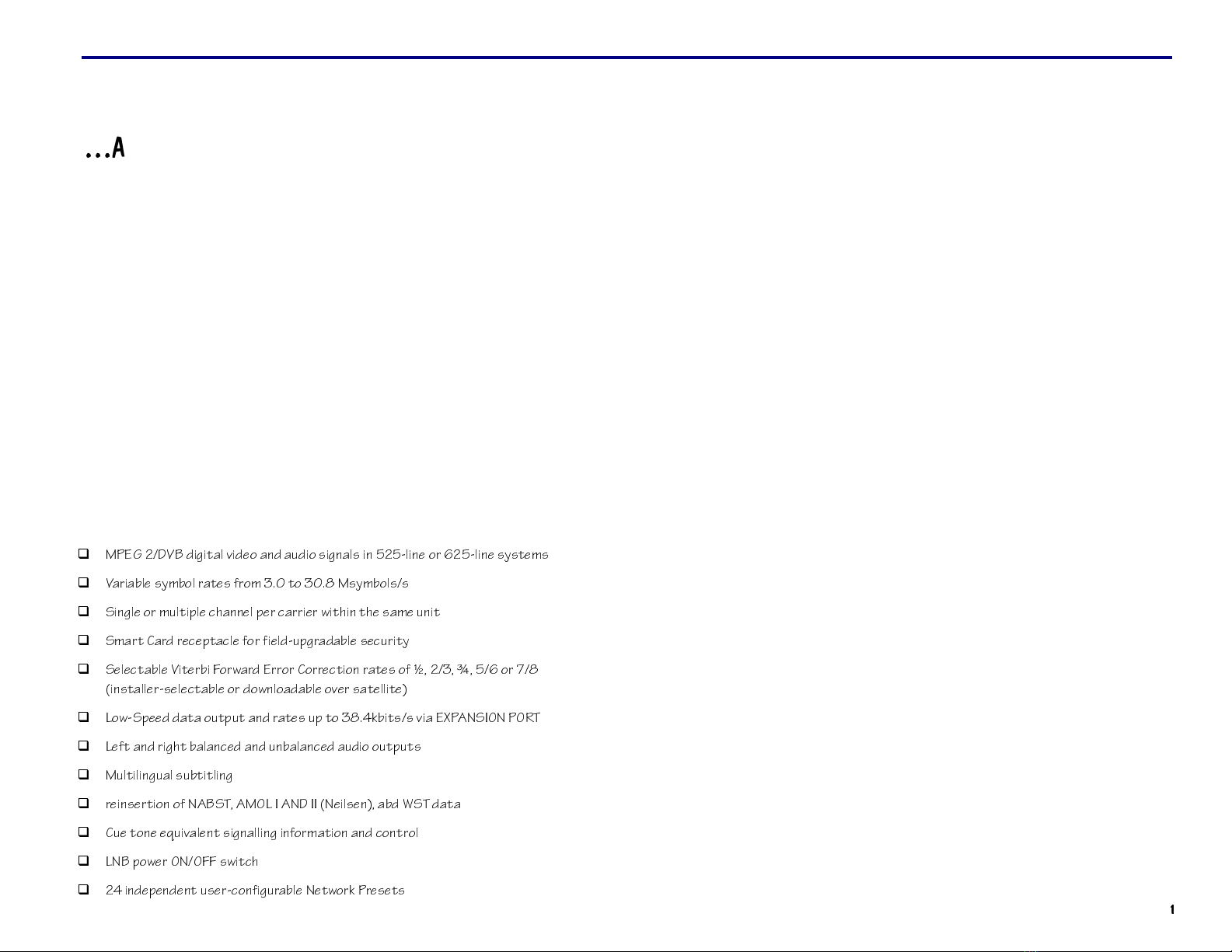
,QWURGXFWLRQ
MPEG 2/DVB digital video and audio signals in 525-line or 625-line systems
Variable symbol rates from 3.0 to 30.8 Msymbols/s
Single or multiple channel per carrier within the same unit
Smart Card receptacle for field-upgradable security
Selectable Viterbi Forward Error Correction rates of ½, 2/3, ¾, 5/6 or 7/8
(installer-selectable or downloadable over satellite)
Low-Speed data output and rates up to 38.4kbits/s via EXPANSION PORT
Left and right balanced and unbalanced audio outputs
Multilingual subtitling
reinsertion of NABST, AMOL I AND II (Neilsen), abd WST data
Cue tone equivalent signalling information and control
LNB power ON/OFF switch
24 independent user-configurable Network Presets
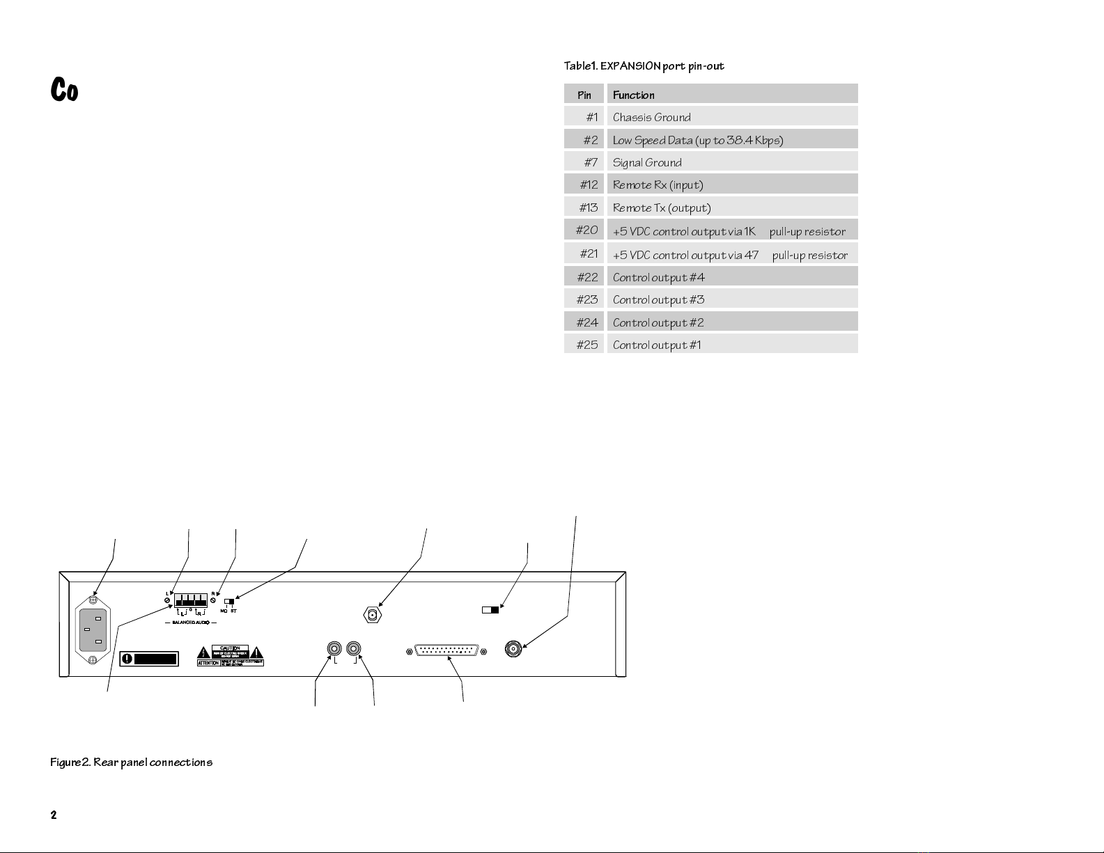
&RQQHFWLQJ\RXUV\VWHP
The following information is provided to help you set up and connect the Headend
Satellite Receiver to the satellite antenna, TV monitor, and other A/V
(Audio/Video) headend equipment. The accompanying figure shows receiver rear
panel connections for the NTSC receivers base version. For equipment intercon-
nection details, see “TV & RF plus optional connections”.
…$ERXWWKH(;3$16,21SRUW
The Headend Satellite Receiver can be operated and monitored remotely via the
EXPANSION port when connected to a PC workstation or data terminal. Remote
receiver operation requires installation of a PC/data communications program.
Note that certain program settings may vary, depending on the type of worksta-
tion/terminal equipment being used. Data interface cables connected between the
Headend Satellite Receiver and some customer equipment may require a unique
pin-out for proper operation via the EXPANSION port (DB-25 female connector).
For port pin-out information, see the accompanying table. Note that only those
EXPANSION port pins used are shown (i.e., all other pins are unused, or are not
required for normal operation).
LNB POWER SW.
TO PC/WORKSTATION
OR DATA TERMINAL
(OPTIONAL)
TO SATELLITE ANTENNA
STEREO/MONO
AUDIO SELECT SW.AC POWER SOCKET
TO L/R BALANCED AUDIO INPUT
TERMINAL BLOCK (CABLE HEADEND)
L/R BALANCED
AUDIO OUTPUT
LEVEL CONTROLS TO VIDEO INPUT (CABLE HEADEND)
OR EXTERNAL MODULATOR
TO AUDIO INPUT (CABLE HEADEND)
OR EXTERNAL MODULATOR
803-297
Scientific
Atlanta
Satellite Television Networks
SATELLITE
LNB PWR
+13/+19V 500mA MAX
AC IN 100V-240V ~AC
50/60Hz 1.4A MAX
AUDIO
RL EXPANSION PORT
VIDEO
ON OFF
LNB PWR
This apparatus
must be earthed
Figure2. Rear panel connections
Table1. EXPANSION port pin-out
Pin Function
#1 Chassis Ground
#2 Low Speed Data (up to 38.4 Kbps)
#7 Signal Ground
#12 Remote Rx (input)
#13 Remote Tx (output)
#20 +5 VDC control output via 1K
Ω
pull-up resistor
#21 +5 VDC control output via 47
Ω
pull-up resistor
#22 Control output #4
#23 Control output #3
#24 Control output #2
#25 Control output #1

795)SOXVRSWLRQDOFRQQHFWLRQV
The accompanying figure shows the cable connections required for the satellite
LNB and TV monitor plus other (optional) connections that can be made from the
rear panel of your Headend Satellite Receiver. As many different equipment con-
figurations are possible, use the following information as a guide only. If you need
assistance to identify your specific equipment configuration needs, contact your
dealer/reseller or local service provider (see also “Connecting your system”).
Satellite antenna LNB and TV monitor connection
Connect the coaxial RF cable from the satellite antenna LNB to the receiver
SATELLITE jack
Connect a coaxial cable from the receiver VIDEO output jack to the TV monitor
VIDEO IN jack (optional), or to external headend TV modulator equipment
LNB power supply switch setting
Set the satellite LNB power switch (near SATELLITE connector) to OFF for using
the external LNB power source, or to ON for using the internal receiver LNB power
source (LNB power switch set to ON permits software control over the LNB power
supply output voltage from the receiver if switchable LNB connected)
Audio connections & level control
Unbalanced AUDIO:
Connect A/V cables from the L (Left) and R (Right) receiver
AUDIO output jacks to the AUDIO IN jacks of your headend A/V equipment
(optional)
Balanced Audio:
Connect separate conductors from the L (Left, +/-) and R (Right
+/-) receiver balanced audio output terminals plus the G (Ground) terminal to the
balanced audio/ground terminals of your headend A/V equipment
Level Control (Balanced Audio):
If necessary, change the Left and Right preset
audio channel signal levels higher or lower (i.e., from unity gain) adjustable
±
6dBby
rotating the potentiometers marked L and R (across from balanced audio output
terminals) clockwise or counterclockwise, respectively
Stereo/Mono balanced audio output switch setting
Set the MO/ST slide switch (near balanced audio output level control) to MO for
monaural audio output, or to ST for stereo audio output to your headend A/V
equipment
Scientific
Atlanta
Satellite Television Networks
SATELLITE
LNB PWR
+13/+19V 500mA MAX
AC IN 100V-240V ~AC
50/60Hz 1.4A MAX
AUDIO
RL EXPANSION PORT
VIDEO
ON OFF
LNB PWR
This apparatus
must be earthed
DATA PORT
TV Monitor Audio
& Video/RF Inputs Satellite Antenna LNB
(RG-6 cable)
AUDIO
IN
RLVIDEO
RF IN
L/R Balanced Audio Inputs
p/o Headend System
Equipment
1
(partof)
1
803-297
Figure3. TV & RF plus optional connections

This Installation and Operation Guide provides all the information you need to
setup and operate your PowerVu Headend Satellite Receiver.
)URQWSDQHOFRQWUROVGLVSOD\
The front panel of your Headend Satellite Receiver provides controls for switching
the receiver on and off, switching the receiver to Alt Mode operation, activating
and navigating menus, and for interfacing with the Smart Card. A Signal presence
LED and an Alternate Mode indicator LED are provided. A 4 digit, 7-segment LED
display provides visual identification of current receiver settings, and also pro-
vides user feedback when changing the current receiver setup via the front panel.
An introduction to each of the front panel buttons and indicators follows.
67$1'%<EXWWRQ
The STANDBY button switches the Headend Satellite Receiver on and off
(standby).
To switch the receiver on or off from the front panel
Press
STANDBY
.....................................................................................................................................
STANDBY
When the receiver is switched on, the front panel LED display is ON. When
switched off (standby), all indicator and display LEDs are OFF, and a single dot
flashes ON and OFF, repeatedly.
0(18EXWWRQ
While viewing any channel you can use the MENU button (front panel) to display
the Main Menu.
To display the Main Menu
Press
MENU
...............................................................................................................................................
MENU
6,*1$/LQGLFDWRU/('
The Signal indicator LED is ON when your Headend Satellite Receiver is synchro-
nized with the incoming digital video signal. If no incoming signal is detected or
recognized by the receiver, or if the receiver setup is incorrect, this LED is OFF. If
the incoming signal or signal synchronization is temporarily interrupted or lost,
this LED may turn OFF or may flicker (i.e., turn ON and OFF intermittently). Also,
if the receiver is not authorized to receiver programming via the local service pro-
vider, the SIGNAL LED flashes ON and OFF (i.e., ON and OFF). For more infor-
mation about troubleshooting your Headend Satellite Receiver, see “Appendix B
Troubleshooting”.
$/70RGHLQGLFDWRU/('
The ALT Mode indicator LED flashes ON and OFF when your Commercial Satel-
lite Receiver is operating in Alt-1 Mode, and is ON when operating in Alt-2 Mode.
When operating the receiver in Alt Mode, you can use the front panel keypad Alt
Mode functions to change the current receiver setup. When the receiver is in nor-
mal operating mode, this LED is OFF. For information about using Alt Mode func-
tions to operate your Headend Satellite Receiver, see “Setting up the receiver”.
6HJPHQWGLVSOD\
Visual identification of current receiver settings is provided by a 4 digit, 7-segment
LED display. The display provides you with immediate feedback when making
changes to the current receiver setup via the front panel buttons. When the receiver
is switched on, the 7-segment display shows the current channel.
2SHUDWLQJWKHUHFHLYHU
$/7
6,*1$/
MENUSTANDBY
Headend Satellite Receiver
Smart Card SLOT
SIGNAL PRESENCE
INDICATOR LED
ALT MODE
INDICATOR LED
MENU BUTTON
NUMERIC KEYPAD AND
MULTI-FUNCTION BUTTONS
ON/STANDBY
BUTTON
ALPHA-NUMERIC
DISPLAY WINDOW
C/Ku FEC S.Q.
MODE
FREQ
SYM SIG
POL AFC
VIEWALT
123
456
789
0
SELECT
Figure4. Front panel controls and display

0
8/7,
)
81&7,21
NH\SDG
The multi-function keypad includes the
Ï
,
Ð
,
Í
and
Î
arrow buttons and the
SELECT button. Use the arrow buttons and the SELECT button to operate the on-
screen menus. The arrow buttons are found on the receiver front panel together
with the SELECT button. You use the SELECT button separately to make selections
from on-screen menus, and together with the arrow buttons to perform special
functions (see also “Front panel controls & display”).
While viewing any channel you can use the
Ï
/
Ð
arrow buttons to display (higher
or lower) channels, and the
Í
/
Î
arrow buttons to increase or decrease the vol-
ume level, respectively. Note that
Ï
/
Ð
arrow buttons control available channels
only (see also “CHANGING channels” and “CHANGING the volume”).
To use the arrow buttons and the SELECT button
Press
Ï
and
Ð
...............................................................................................................................
Press
Í
and
Î
.............................................................................................................................
Press
SELECT
................................................................................................................................................
1
80(5,&
NH\SDG
While viewing any channel you can use the front panel buttons to change the cur-
rent receiver setup by switching from normal receiver operation to one of two (2)
alternate operating modes (i.e., Alt Mode-1 and Alt Mode-2). For more information
about Alt Modes, see “Setting up the receiver”.
While in normal operating mode (i.e., front panel ALT LED OFF), you can use the
front panel numeric keypad to change any channel from 001 through 999, or to
enter information for menu options (see “Setting up the receiver”).
To use the numeric keypad (normal mode operation)
Press
0
through
9
.............................................................................................................
To use the numeric keypad (Alt Mode operation)
Press
ALT
..................................................................................................................................................
Press
VIEW
..............................................................................................................................................
Use the VIEW button to return to normal receiver operation from Alt Mode. Other
Alt Mode functions are also available via the front panel. For complete information
about viewing or changing the current receiver setup using Alt Mode functions,
see “Alt Mode operation”.
6
0$57
&
$5'
VORW
Security and/or preauthorized satellite broadcast services upgrades via Smart
Card are planned in future for the PowerVu Headend Satellite Receiver.
&
+$1*,1*
FKDQQHOV
While viewing any channel you can change channels (higher or lower) one channel
at a time. Channels are changed (higher or lower) depending on which button is
pressed.
To change channels
Press the Up
Ï
and Down
Ð
arrow buttons...................................................................
Channels can also be changed directly by pressing the numbered front panel but-
tons (e.g., to change to channel 5, press 0005, or press 5 and then SELECT).
&
+$1*,1*
WKHYROXPH
While viewing any channel you can increase or decrease the volume level. The
volume level is increased or decreased depending on which button is pressed.
To change the volume
Press the Left
Í
and Right
Î
arrow buttons................................................................
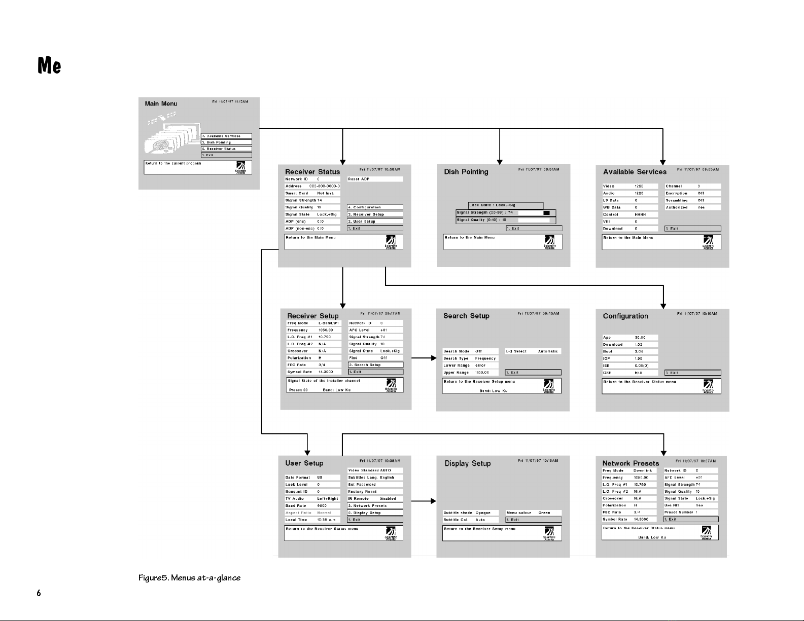
0HQXVDWDJODQFH
Figure5. Menus at-a-glance

This section provides important operating information regarding the setup and
operation of your PowerVu Headend Satellite Receiver and satellite antenna signal
source, including signal search. Before you begin using the receiver, it is important
that you read all of the information in this section first. If you are modifying your
receiver or system configuration, you may need to change the current settings to
suit your operating requirements.
Because some or all of the receiver setup can be Password-protected, you may or
may not be permitted to make changes to the current settings.
Using the receiver front panel buttons you can
Activate and navigate the on-screen menus via the menu interface
Operate the receiver in Alt Mode via the Alt Mode interface
View or change the current receiver setup
Select and view available satellite programs or events
Both the menu interface and the Alt Mode interface can be used interchangeably
for performing most receiver setup tasks, since both are operated via receiver op-
erating system software. However, not all menu interface functions are duplicated
by the Alt Mode interface. Depending on how you have installed and connected
the Headend Satellite Receiver, you may or may not be able to use the menu inter-
face. If the receiver is connected to a TV/video display monitor, you can view or
change the current receiver setup via on-screen menus. Conversely, if no TV/video
display monitor connection is available, only the front panel Alt Mode interface
can be used for receiver setup, and you will not need to reference instructions pro-
vided for operating the various menus.
…$ERXWWKH$OWHUQDWH0RGHLQWHUIDFH
While viewing any channel, you can use Alt Mode functions to view the current
receiver setup, or you can view or change the current setup from the Installer
Channel. Alt Mode functions are available via receiver front panel buttons. Alt-1
function labels are printed directly on the keypad bezel above each button (see
Figure 4). Alt-2 functions are also associated with front panel buttons, except that
the function names are not printed on the keypad bezel (see “…About entering
numbers using front panel buttons”). As with the menu interface, access to Alt
Mode functions is controlled by system Lock Levels and the security Password.
More information about Lock Levels and the Password is contained in this section.
For detailed information about how each of the Alt-1 and Alt-2 functions are used
to set up the receiver, see “Alt Mode operation”.
…$ERXWRSHUDWLQJWKHRQVFUHHQPHQXV
While viewing any channel, you can display on-screen menus for viewing or
changing the current receiver setup. While in menus, you can change the current
receiver settings, and/or display other menus. Some menus contain setup infor-
mation which is available for viewing only, and cannot be changed. Numbered
menu options are used to display other menus. Access to menus and changeable
menu options is controlled by system Lock Levels and a security Password. For
more information about Lock Levels and the Password, see “…About the Pass-
word”.
To display on-screen menus
Press the
MENU
button on the receiver front panel.
To change a receiver setting
Step 1.
Move to the desired setting using the
Ï
,
Ð
,
Í
and
Î
arrow buttons.
Step 2.
For numeric entry options, press SELECT to clear the display field, enter the
number and then press SELECT again. For all other options, press SELECT re-
peatedly to display available settings.
6HWWLQJXSWKHUHFHLYHU
IMPORTANT!
Access to your PowerVu Headend Satellite Receiver setup
can be Password-protected. Depending on the current Lock Level setting,
you may be prompted for the Password before you can display on-screen
menus, or before using the Alt Mode front panel interface. Note that if
Lock Level 3 is currently set, pressing any button displays a password
prompt (see
…
About the Password).

Step 3.
After making changes, move to Exit and press SELECT, or press 1 and then
press SELECT. This action displays the Save pop-up menu.
Step 4.
Press 1 to save the new configuration.
To display another menu, or exit from the current menu
Step 1.
Move to the desired menu option using the
Ï
,
Ð
,
Í
and
Î
arrow buttons and
press SELECT, or
Press the number displayed at the menu option (left) and then press SELECT.
When you select EXIT or if you press the MENU button after making changes, a
pop-up menu displays available Save options (see “…About saving changes”).
To display the Main Menu (if Lock Level 3 set)
Step 1.
Press the
MENU
button.
An on-screen prompt displays for entering the current Password.
Step 2.
Enter the current Password and press SELECT to display the Main Menu (for
security, a default character is substituted for each number pressed).
For more information about the Password, see “…About the Password”.
…$ERXWHQWHULQJQXPEHUVXVLQJIURQWSDQHOEXWWRQV
Alt Mode interface: The Alt Mode interface cannot be used for direct numeric en-
try. Some Alt Mode options let you enter values directly using front panel buttons.
To operate the front panel for setting numeric functions while in Alt Mode, per-
form the following actions.
Step 1.
Change to Alt-1 or Alt-2 Mode operation by pressing the ALT button on the
receiver front panel (see Alt Mode operation).
Step 2.
Press the
Ï
or
Ð
arrow button to change the currently displayed value higher
or lower, as required, and then press SELECT.
Each change made must be saved before exiting (see “…About saving changes”).
Pressing the
Ï
or
Ð
arrow button displays available options (numbers) in fixed
steps. Note that stepping speed increases if you press and hold down the arrow
button.
If the selected value is out of range or conflicts with another setting, a pop-up mes-
sage displays information about the error, or substituted (default) value. For a list
of frequency-related error messages, see Table 6.
Menu interface: Some menu options let you enter values directly using front panel
buttons. To enter numbers directly and to operate numeric functions, perform the
following actions.
Step 1.
Press
SELECT
(after moving to the desired option) to replace the current
setting. This action also clears the display field.
Step 2.
Press the front panel buttons to enter the number.
Each number entered is displayed on-screen (decimal places may also display
automatically). If you make a mistake while entering numbers, press the
Í
or
Î
arrow button to clear the entry and start again.
Step 3.
Press SELECT after completing the numeric entry.
Changes made must be saved before exiting (see “…About saving changes”). If
you press SELECT to clear the entry, pressing the
Ï
or
Ð
arrow button displays
available options (numbers) in fixed steps.
Repeat this action to change the current setting. If a value entered is out of range or
conflicts with another setting, a pop-up message displays information about the
error, or substituted (default) value. For a list of frequency-related error messages,
see Table 6.
…$ERXWVDYLQJFKDQJHV
Alt Mode interface: After making changes to the current setup via any Alt Mode
function, you must save or discard the changes. Saved changes are used to update
the current receiver settings which are stored in non-volatile memory. Discarding
changes restores the previously saved settings. You can also cancel the operation to
make further changes. For more information about Alt Modes, see “Alt Mode op-
eration”.
When you press the ALT, VIEW or STANDBY button after making changes, “sav?”
is displayed at the front panel (see Figure 4).
Table of contents
Other Scientific Atlanta Receiver manuals

Scientific Atlanta
Scientific Atlanta PowerVu D9850 Operating instructions

Scientific Atlanta
Scientific Atlanta PowerVu D9234 Operating instructions

Scientific Atlanta
Scientific Atlanta 9660 Operating instructions

Scientific Atlanta
Scientific Atlanta Explorer 8300 User manual

Scientific Atlanta
Scientific Atlanta PowerVu D985 Operating instructions

Scientific Atlanta
Scientific Atlanta Cox Business Video Digital Receivers User manual

Scientific Atlanta
Scientific Atlanta PowerVu D9228 Operating instructions

Scientific Atlanta
Scientific Atlanta PowerVu D9834 User manual


