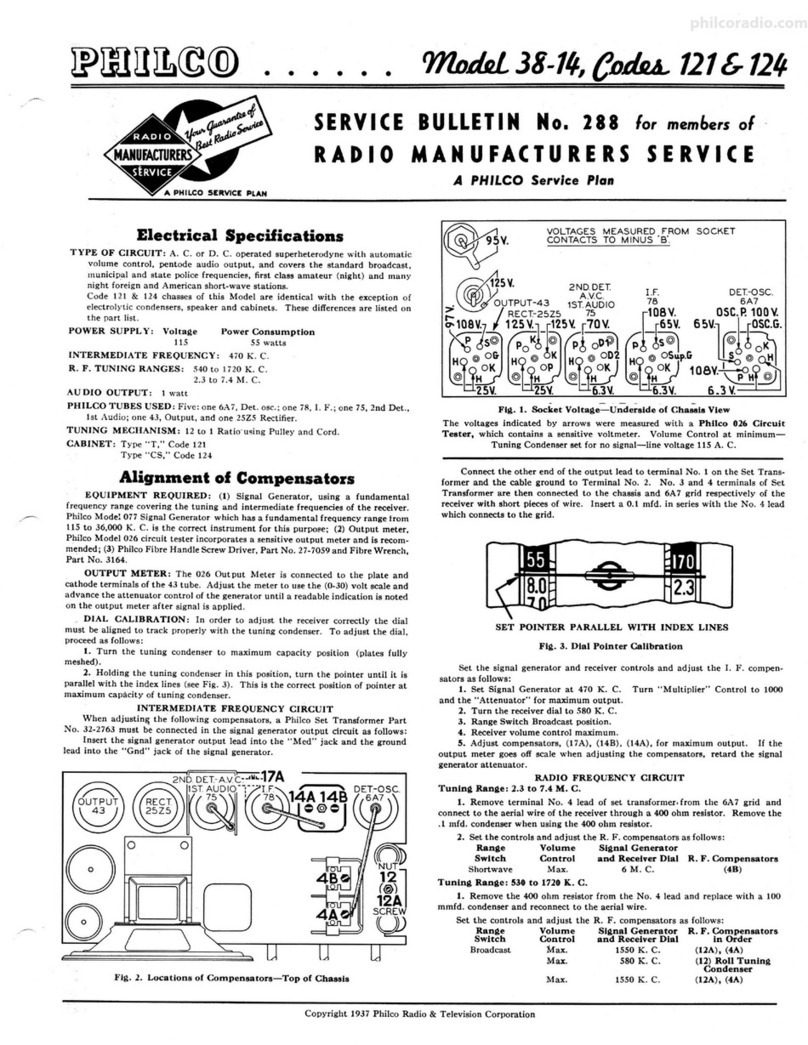
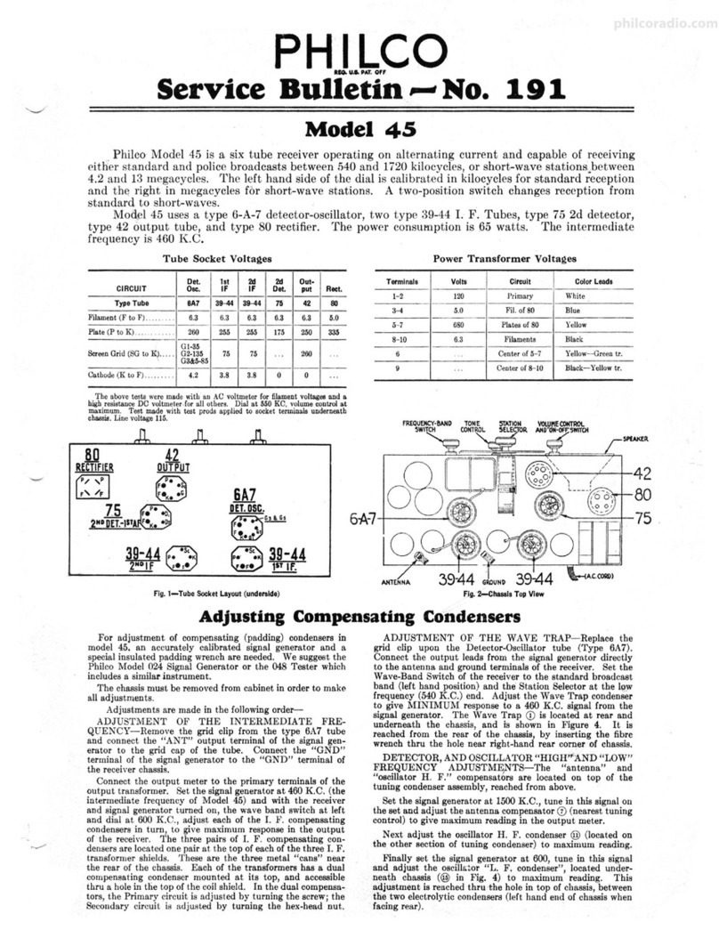
Philco 76 User manual

RADIO
Operating
Instructions
for
Model 76
Screen Grid Receiver
Philadelphia Storage Battery Company
Ontario and C Streets
Philadelphia, Pa,, U. S. A.
'ti

rl
PHIL('O RADIO 1A'^STRUCTIOIlS
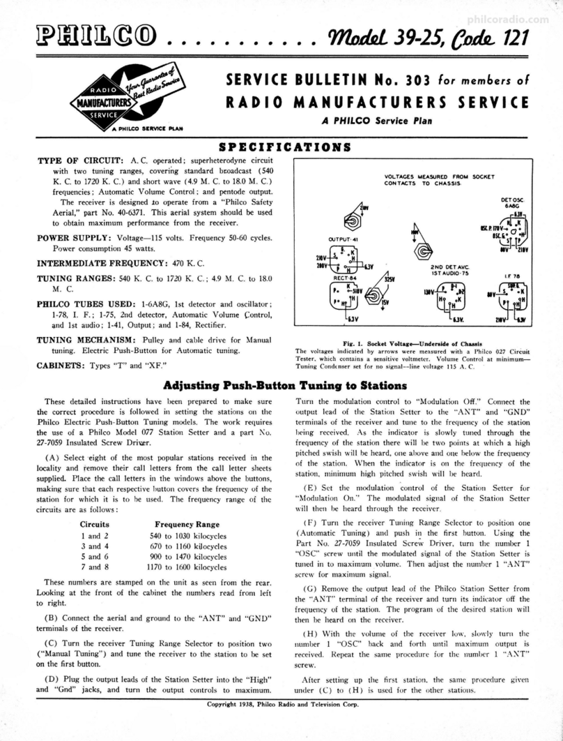
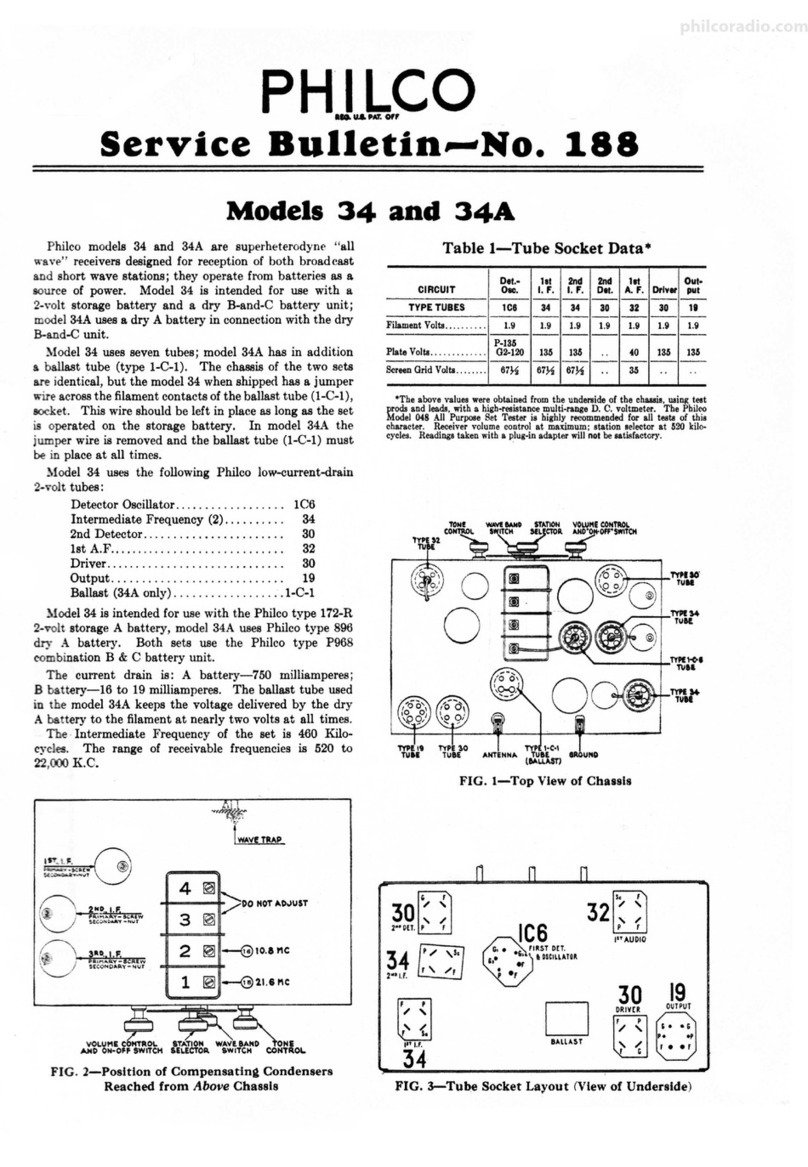
The Philco Model 76 Screen Grid Re-
ceiver is to be used only on an alternatin$
current supply of 50 or 60 cycles, 100 to
135 volts.
If connected to a direct current supply
such as is used in some hotels, apartments,
stores and houses in large cities, the Re-
ceiver will be damaged.
Do not insert the attachment plu$ in
the house socket until all other connections
are made and the speaker plug and all tubes
are in the sockets.
STATION SELECTOR
(lrwavs ruN e,lccuurrlv)
--r
swrr.cH
VOLUME
CONTROL
---f--
280
TYPE
TUBE
LOCAL-DI STANCE
SWITCH ON.OFF
AERIAL AND GROUND
TERMINAL POSTS
245
TYPE
TU BES
227 TYPE
, TUBE
SPEAKER PLUG
(DO NOT TURN
RECEIVER ON WITH
THIS PLUG REMOVED)
224
(scneeN onto)
TYPE TUBES
THIS SHIELD MUST BE
IN PLACE BEFORE
OPERATING RECEIVER
THESE CLIPS MUST BE
CONNECTED TO CAPS ON
TOPS OF TUBES Fig. 1

PHILCO RADIO 1.^/STRUCTION^S
I
I
I
Model 76
Tubes
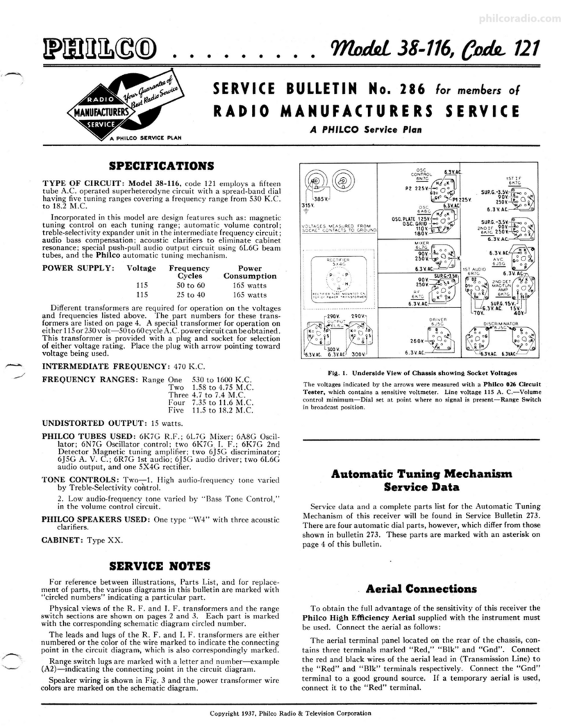
Seven tubes are required, as follows:
3IJY224 Screen Grid Tubes, or equivalent
I UY227 Audio Amplifier Tube, or equivalent
2IJX245 Power Amplifier Tubes, or equivalent
I UX280 Rectifier Tttbe, or equivalent
Remove the large tube shield across the back of the
Receiver by loosening the four screws along the bottom and
lifting straight up on the shield.
Place the tubes in the correet sockets as shown in Figure 1.
After inserting the screen grid tubes (Uy224), the clips
attached to the wires coming from the round shields must
be pressed dolvn over the terminal caps on top of the tubes.
Replace the tube shield over the three tubes at the back
of the Receiver and tighten the fottr screws to hold it in
place.
Speaker
The Philco Electro-D5'namic Speaker is built to work
with the Philco Receiver. It is connected by inserting the
Speaker plug in the special socket at the back left-hand
corner of the Receiver. This socket is shor,r'n in Figure 1.
Never turn on the Receiver unless the Speaker plug is
in place in the socket.
Aerial or Aqtenna
An outdodr aerial, consisting of a single copper lvire 50
to 100 feet long, usually gives the best results. Holvever,
where there is no powerful broadcasting station u'ithin 50
miles, a longer aerial may be used and will bring in far-away
stations with somewhat greater volume. The lead-in u'ire is
an active part of the aerial and the aerial length should
always be measured from the Receiver to the insulator at
the far end. The outer end of the aerial should be as high
as possible and the entire aerial should be spaced well away
from trees and buildings and supported by glass or porcelain
insulators.

[-
I
.tE.-
PHILCO RADIO lNSTRUCTIONS
Good results can also be obtained rvith an indoor aerial
25 feet or more in length. A shorter aerial usually rvill not
be satisfactory.
Ground
A suitable ground clamp must be securely attached to a
radiator valve or water pipe and the bare wire end inserted
in the " GND " terminal post of the Receiver.
Never operate the Receiver without a $ood $round
connection.
Use separate insulated wires rather than a two-lvire cord
for the aerial and ground connections.
Operating the Receiver
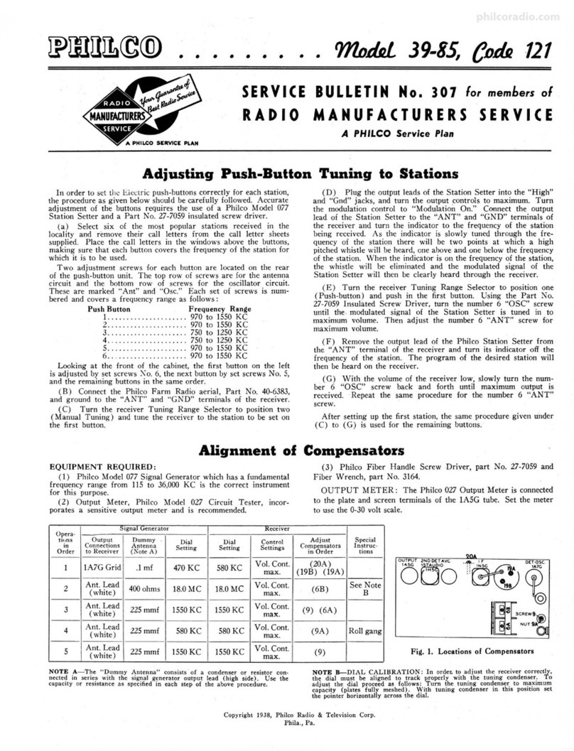
After making the aerial and ground connections, placing
all tubes in the sockets and inserting the Speaker plug in
its special socket. the attachment plug on-the cord should
be inserted into a convenient wall receptacle. Turn on the
Receiver by rotating the on-off switch in a clockwise direc-
tion. The pilot lamp should light, indicating that the pou'er is
turned on. (When the on-off switch is turned off. no power
is used and the attachment plug need not be withdrawn.)
Wait about a minute after turning on the Receiver for
the tubes to become heated, then turn the volume control
(left-hand knob) clockwise about one-half the total range- of
movement. Also turn the "local-distancel' srvitch (right-
hand knob) clockwise, that is, to the " distance " position.
Then turn the station selector (center knob) and different
stations will be tuned in at various points on the scale.
Tune the wanted station accurately to the point where
it is clearest and reduce or increase the volume as desired
with the volume control and the "local-distance" switch.
Never reduce the volume of a station by detuning with the
station selector as this will spoil the tone quality.
The "local-distanee" switch should be used in the "dis-
tance" position at all times except when listening to a strong
nearby-broadcasting station. On extremely strong signals
bettei tone quality will usually be had with this switch in the
"local" positlon. Distant stations will not be heard with the
switch in the t t loeal t t position. (corilit*tetr on poue ,5)
4

PHILCO RADIO 1,4/STRUCTIO,^rrS
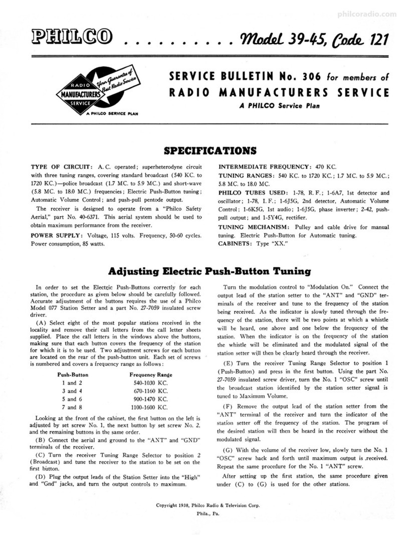
Always regulate the volume by means of the "volume
control " and the " local-distance " switeh -never by detuning.
Undistorted reproduction will be obtained
up to the full output of the two 245 power
tubes as the volume control is turned up.
Turning the volume control further may
reduce rather than increase the volume or
even cut off the station so that nothing
will be heard. The volume control is de-
signed to operate in this way on strong
stations.
Standard Warranty
We wamant each new Radio Receiuer and Spealter nl,anxl-
factured by us to be free from defects in material and work-
manship under normal use and seruice, our obligation under
this warranty being limited to making good at our factory or
factory depots any part or parts thereof which shall, within
ninetE @0) daAs after deliuerg of such Receiuer to the original
purchaser, be returned to us with transportation charges pre-
paid, and which our eramination shall disclose to our satis-
faction to haue been thus defectiue; this warranty being erpressly
in lieu of all other wamanties erpressed or implied and of all
other obligations or liabilities on our part, and we neither
assunl,e nor authorize any representatiue or other person to
assun'te for us any other liability in connection with the sale of
our Receiuers or Speakers.
This wamanty shall not apply to anE Receiuer or Speaker
u'h.ich shall haue been repaired or altered outside of our factorg
or factory depots in any ua?J so as, in our judgment, to afrect
its stability or reliability, nor which has been subject to misuse,
negligence, or accident, nor uthich has had the serial number
altered, efaced, or remoued. Neither shall this u,arrantE applA
to any Receiuer or Speaker which has been connected otherwise
tltan in accordance uith th,e instru,ctions furnished by us.
We make no uarranty whateuer in respect to tubes, inasmuch
as they are usually uarranted bg their respectiue manufacturers.
PHILADELPHIA STORAGE BATTERY CO.
Ontario and C Streets
Philadelphia, Pa., U. S. A.
5
KILO-
cYcLts STATIONS PH I LCO
SCALE
CHANN EL
NUMBERS STATIONS METERS
550
600
650
700
750
800
E50
900
950
r000
1050
1100
ll50
1200
t250
1300
1350
1400
1450
1500
WGR_}vEAN
wtoD
WFI-WLIT
wMcA-\ilMC
wtBo-wwNc
WKAQ
KHQ-WOW
WEEI
KFSD
WIP-WFAN
KGIV_WTMJ
wos
KFI
wsM
WEAF
WMAO
WPTF_KPO
CANADA
wLw
11'oR
WGN
CANADA
wsB
wJR-WCX
wJz
WBBM-WJB'f
wMc
KGO-WCY
WBAP-WFAA
wcco
WHAS
KOA
CANADA
wABC-CMC
WENR_WLS
CANADA
KHJ
KOMO
I(OIN_KGU
KLDS_WRC
CANADA
KJR
KDKA
wBz-wBzL
KYW_KFKX
CANADA
KTHS_I(RLD
KNX
WBAL_WTIC
WBT_lvTAM
KMOX-KFQA
wPc-wLwL
KSOO-}VRVA
I(SL-WJJD
WHAM
wowo-wwv^
WCAU
WOAI
KYA_WNAC
KI(L
KOIL_WJAX
WCAM
KDYL
lv^DC
KGB
KLRA-KUOA
I(GRS
KTBS
WJSV_KSTP
WORD-WCKY
s'LA(]-\JVTNT
55 545
499
461
428
400
375
353
333
316
300
285
273
261
250
240
231
222
2t4
207
200
60
i5
IO
75
-80=
E5
-90=
95
-100=
r05
il0
:ll5=
r20
t25
r30
r35
t4t
145
150
trl
,i!;d'! i X
Eg 6 - N-o
H')ei-:--
s:3*fr5,
3;8368
g€C.H=:
o >5! i cnH
I OW - O
-:=-trrl>X'C'c.r o 9E
i- >rE=+ c€
c) C cJ€ d: q/
^-: ts :i u-
'a -^ d) ! D -, -
=.9,--o=iu
= q) t E:* o
itsyuH?-
(,]O{-e-YOr
'J 3*:FH >e
? 6r.U; S A
t# EE< i-t
ei,o.! .la
5vr>;='r
F-{+?, d.= - tr
- a al H - bo
-- =
L lAJi o) X € e
^F^@-l
5::=e+bci;
.' .:- ?
Y ! Y Ma 6)
"Ef oI.F y€
:tE=5€s
.:- d X a F o>
90 E5tF:sE
O Eav, iP.E-
Fl S P 6 3 66'i
r E:ilftHg
.Fl ;-c -.;i+=
€ f,a.g s.*'s
g ;l:ge:e
o 3 I:EE.E:
-g €::,3+s€ F
.!l 3E@ P cn tr i
€ [E o 6.E 8.e
0.r .i;iF'X:ts
) i ^ 9 69
== i'O ! e (,
) d tr tio -
- >rt cn Q-=
€= I bc.,'= U
:.9d fi€ 3 c
! -''s :i !
f 7;1g2'ai
4 ei li.F:
9;i.-* a >i l
?-E7 r oSP
i c ^E €r o)
: =':E- h
r )!
l3 c€ c o qE
o=E y.a? i I
!; b e.;€:
:E€sh5+
';?1 e c€ a j4 r
/-'
*EEqEEE
9 9:: E;- F
4 9,gE #: 3
I aC.H r€ c,
h I F J O'ci
€ K ['g:: H
.nY?a66-
.-r9AU.1
5.F: I3E *
- ar€tE E'
-c)
7-=)V1
-,;ts H;€
Table of contents
Other Philco Receiver manuals

Philco
Philco 38-14 Reference manual

Philco
Philco 30 User manual

Philco
Philco 38 User manual

Philco
Philco 41 User manual

Philco
Philco 50 User manual

Philco
Philco 39-25 Reference manual

Philco
Philco 121 Reference manual

Philco
Philco 95 User manual

Philco
Philco 45 User manual

Philco
Philco 38-116 Reference manual
Popular Receiver manuals by other brands

JVC
JVC KW-AVX848 Connect and set up

Telonics
Telonics TSUR-400 Operation and programming manual

Hammarlund
Hammarlund hq-150 Technical description and operating instructions

Radio Shack
Radio Shack DX-399 owner's manual

Sony
Sony STR-DH100 Service manual

Sirius Satellite Radio
Sirius Satellite Radio Stream Jockey II XTR2CK instruction manual