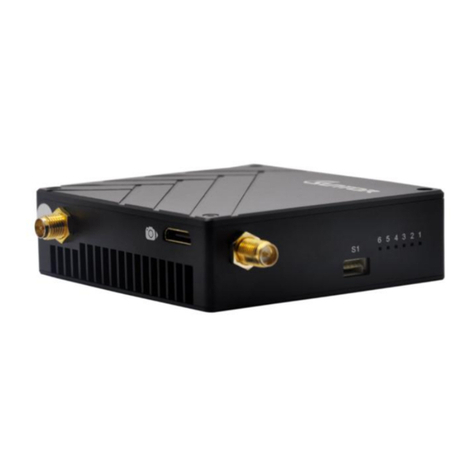
Suntor ST15NMT-MiNi User manual

1
ST15NMT-MiNi User Manual
SUNTOR ELECTRONICS CO., LIMITED

2
Contents
Ⅰ、 Product Appearance............................................................................................................................................. 3
Ⅱ、Product Intro............................................................................................................................................................. 3
Ⅲ、Equipment Install.....................................................................................................................................................4
3.1 Interfaces Describe............................................................................................................................................ 4
3.2 Basic Parameters................................................................................................................................................ 5
3.3 Cautions................................................................................................................................................................ 5
Ⅳ、Equipment Debug....................................................................................................................................................6
4.1 Prepare of Debug...............................................................................................................................................6
4.2 Equipment Login................................................................................................................................................ 7
4.3 Set Central Node/ Access Node.................................................................................................................... 7
4.4 Modify IP Address..............................................................................................................................................8
4.5 Set WLAN............................................................................................................................................................. 9
4.6 Set Bandwidth..................................................................................................................................................... 9
Ⅴ、Use Notes................................................................................................................................................................. 10
Ⅵ、Normal Faults and Treatment.......................................................................................................................... 11
Ⅶ、Accessories.............................................................................................................................................................. 12
Focus on wireless make transmission easier(End).......................................................................................13

3
Ⅰ、Product Appearance
Ⅱ、Product Intro
The ST15NMT-MiNi UAV wireless transmission link is an Ad-hoc network device, it's
good performance in NLOS transmission. The device wireless module adopt
Qualcomm chip and three-frequency design, it support 2.4G(2401.5-2481.5MHz
),1.4G(1427.9-1447.9MHz)and 800M(806-826MHz). When it's in 1.4G frequency, it
can realize a high throughput Ad-hoc network transmission in a long LOS distance.
When it's in 800M frequency, it can realize fast mobile Ad-hoc network transmission
in a NLOS complex environment. In our testing, the NLOS distance is 1-3KM, the LOS
distance is 10-20KM.
The ST15NMT-MiNi RF power is 300mW, its features of low power consumption,
small in size, quick to install, strong penetration transmission and long range
advantages, is very suitable application for manpack video transmission, UAV,

4
Unmanned ship, Unmanned car, Airship, Target drone, Powered parachute, Robot and
other fields for video signal transmission, police video forensics, emergency monitor
and rescue sites.
Ⅲ、Cautions
The device data interface is designed by air plug. If it needs to be extended during
use, please use the direct network cable. The direct network cable sequence is defined
as follows:
Special attention: before the equipment is powered on, please carefully confirm
whether the antenna is correctly connected, so as to avoid unnecessary trouble and
economic loss caused by damage to the equipment.
Ⅳ、Equipment Debug
4.1 Prepare of Debug
Before debugging, ensure that PC and device IP in the same network segment.
Factory default parameters: IPv4 address: 192.168.1.1; Subnet mask: 255.255.255.0;
The IP of the computer should be set to 192.168.1.x (X= any number between 2 and
253, which does not conflict with the device address).
The subnet mask:255.255.255.0。

5
The steps to modify computer IP:
4.2 Equipment Login
1. Open IE browser, input the IP of the device in the address bar: 192.168.1.12,
log in the device and select "Management Login", the default IP of the device
is: 192.168.1.12, username and password is: admin123.

6
2. User name: admin123 password:admin123 click login
4.3 Set Central Node/ Access Node
The device has two working modes: Central Node/ Access Node. After logging into
the device through the browser, the following actions are required to change the
device's working mode. After entering the page, click "Master and Slave Setting",
select "Master and Slave Setting" to set the device's working mode, and click "OK" to
complete the configuration. As shown in figure:
choose“Management Login”
User name:admin123
password:admin123
click login

7
4.4 Modify IP Address
Enter the device IP address in the browser and enter the device management p
age. Click "Network Parameter Setting" and select "IP setting" to modify the de
vice IP address. Click "OK" to complete IP modification, as shown in figure:
4.5 Set WLAN
When setting the working frequency of the device, click the "Wireless Setting" button
and select the "Frequency Band" option to enter the operation interface. The device
Select the working mode of the node,
Central Node/Access Node
Set an IP

8
supports the RF 800M frequency band and 1.4G frequency band. The 2.4G frequency
band is not open yet. After confirming the frequency, click "Submit" to complete the
configuration. The operation is as follows:
4.6 Set Bandwidth
According to the link throughput demand, users can choose channel bandwidth 1.4, 3,
5, 10, 20 MHz. The narrower the bandwidth, the farther the transmission distance, the
lower the bandwidth, the closer the transmission distance, and the higher the
transmission rate. Different electromagnetic environments exist in different
environments. The frequency can be adjusted to avoid channel interference and
achieve better transmission effect. Click "Wireless Setting", select "Bandwidth", select
the bandwidth and click "OK" to complete the configuration. Operation as shown
below:
Set the frequency band
800MHz/1.4GHz
click "Submit"

9
Ⅴ、Use Notes
●When we adjust and test equipment, make sure that the Tx and Rx are in the same
channel.
●The first time to connect the power supply, please check the power supply voltage
"+ -" is correct.
●Avoid high voltage towers around.
●Avoid military airfield radar around.
●Choose different channels to avoid electromagnetic interference.
● Do not twine the network wire with the power wire, or there will be magnetic
interference.
●Network wire and power wire shall not exceed 20m.
●Set the distance in software as 110%~120% of the actual distance.
●Use caution in thunderstorm weather, people should stay away from the antenna to
avoid lightning accidents.
● The transmitter and the receiver should not to power on before connect the
select the working bandwidth

10
antennas.
Ⅵ、Normal Faults and Treatment
◆Faults cases: if the video (data) suddenly lost, interrupted, can be as follows
suggested
troubleshooting.
Hardware failure:
1. At this point, the first step is to make sure the power supply is normal, according to
the indicator.
2. In case of network failure, the computer needs to be connected to the system
switch to access the equipment, and CMD input Ping 192.168.1.xx (the default IP of
the equipment is 192.168.1.1; xx stands for specific IP), so as to determine whether
the device is online or not. The same method is used to troubleshooting other devices.
If the device returns the request timeout or cannot access the target host, the device
is not online, need to check the power and hardware.
◆Faults cases: if the video (data)lag, lost packet, can be as follows suggested
troubleshooting.
3. The weather and physical vibration may causes the equipment antennas connected
loosely, which leads to poor signal and low throughput, affect image normal viewing

11
and data loss packet.
4. In a complex environment, the same frequency interference may occur, the
problem can be solved by changing the working frequency through the software GUI.
5. If the equipment parameters are changed and the equipment does not
communicate, the parameters can be adjusted according to the above debugging
instructions, also you can restore factory setting, according to the Quick Use Manual
to set.
Ⅶ、Accessories
Item
Quantity
Specification
Remark
1.4GHz mini
Rubber Antenna
2
SMA Internal thread
with needle
3dBi gain
Warranty Card
1
Suntor Standard
After-sale guarantee
Specification
1
User manual
Detail describe the
parameters and how to
use
(End)
Focus on wireless make transmission easier
Table of contents
Other Suntor Transmitter manuals
Popular Transmitter manuals by other brands

Honeywell
Honeywell Midas S2 user manual

HBC-Radiomatic
HBC-Radiomatic spectrum 1 M operating instructions

Evikon
Evikon PluraSens E2618-O3 user manual

Dwyer Instruments
Dwyer Instruments CDX Series Installation and operating instruction manual

Gruber
Gruber RNM-10 instruction manual

YOKOGAWA
YOKOGAWA Dpharp vigilantplant EJA110A user manual