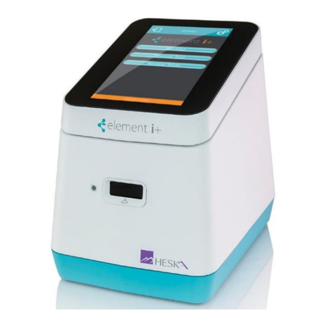
scil Element AIM User manual

1
User Manual
Element AIM
Automated Artificial Intelligence Microscopy
For veterinary use

2
Manual Introduction
This manual contains the following sections.
Preface: General introductory information and explanations of:
•Using this manual
•Contents overview
•Definitions and abbreviations
•Symbols
Safety: Explains the safety labels and precautions.
•Intended use
•User profile
•Application limits
•Information on product liability
•Warnings for intended use
•Safety instructions on the device
•Product description
•Product overview
•Delivery package and contents
•Features
•Analyzer identification
Installation: How to connect power and USB cables and how to accomplish the basic set-up.
Operation: Contains instructions for operating the analyzer.
Maintenance and Care: Explains how to perform basic care activities and regular maintenance tasks
such as opticscleaning. It also contains general advice for storage and shipping.
Troubleshooting: How to troubleshoot error messages that appear on the display, and how to gather
device informationbefore you call service.
Transport, Storage and Disposal: Explains how to transport the analyzer to its intended location, as
well as storage anddisposal guidelines.
Technical Specifications: Lists the technical data for the device described in this manual.Index: Lists
keywords in alphabetical order, with pointers to pages where they occur.

3
Table of Contents
INTRODUCTION
SECTION 1: SAFE USAGE AND HANDLING PRECAUTIONS
1.1 Using This Manual ...........................................................................................................................................................1
1.2 Definitions, Acronyms and Abbreviations........................................................................................................................1
1.3 Symbols ...........................................................................................................................................................................1
1.4 SafetyWarnings...............................................................................................................................................................1
1.5 Product Liability Information ............................................................................................................................................1
1.6 Warnings..........................................................................................................................................................................2
1.7 Safety Instructions on the Analyzer.................................................................................................................................3
1.8 Declaration of Conformity ................................................................................................................................................3
1.9 Disposal ...........................................................................................................................................................................4
SECTION 2: ELEMENT AIM ANALYZER OVERVIEW
2.1 Product Overview.............................................................................................................................................................5
2.1.1 Analyzer Identification............................................................................................................................................5
2.2 Technical Specifications ..................................................................................................................................................6
SECTION 3: TRANSPORT, UNPACKING, PACKING AND INSTALLATION
3.1 Package Contents............................................................................................................................................................7
3.2 Installation Location Requirement ...................................................................................................................................7
3.3 Electrical Requirements...................................................................................................................................................8
3.4 Moving the Analyzer ........................................................................................................................................................8
3.5 Unpacking........................................................................................................................................................................8
3.6 Removing Shipping Locks ...............................................................................................................................................8
3.7 Connections and Operating Controls ..............................................................................................................................9
3.7.1 Computer and Analyzer Connections....................................................................................................................9
3.7.2 Mains Connection..................................................................................................................................................9
3.8 Repacking for Shipment or Storage ..............................................................................................................................10
SECTION 4: ANALYZER OPERATION
4.1 Materials.........................................................................................................................................................................13
4.2 Cartridge Fill Procedure.................................................................................................................................................13
4.2.1 Equipment............................................................................................................................................................13
4.2.2 Preparation Procedure for Urine Samples ..........................................................................................................13

4
4.2.3 Cartridge Filling Procedure for Fecal Samples....................................................................................................15
4.3 Running a Test...............................................................................................................................................................16
4.3.1 Running a Urine Sediment Analysis....................................................................................................................16
4.3.2 Running a Fecal Sample .....................................................................................................................................18
4.4 Confirming and Reviewing Results................................................................................................................................20
4.5 Settings ..........................................................................................................................................................................22
4.5.1 General Settings..................................................................................................................................................22
4.5.2 Administrator Settings..........................................................................................................................................22
SECTION 5: MAINTENANCE AND CLEANING
5.1 Cleaning Outside Surfaces............................................................................................................................................24
5.2 Cleaning Optics..............................................................................................................................................................24
5.2.1 Equipment............................................................................................................................................................24
5.2.2 Cleaning Procedure for Optics ............................................................................................................................24
SECTION 6: TROUBLESHOOTING
6.1 Troubleshooting and Error Handling..............................................................................................................................27

5
Section 1: Safe Usage and Handling Precautions
a) 1.1 Using This Manual
Before starting to use the Element AIM™ Automated AI Microscopy Analyzer (Element AIM) read
through these instructions for use carefully and follow the instructions. Failure to follow the
instructions and safety information in these instructions for use will result in voiding of the
manufacturer warranty.
b) Definitions, Acronyms and Abbreviations
Acronyms
IFU Instruction for Use RPM Revolutions Per Minute
RCF Relative Centrifugal Force: g-force in m/s2
c) Symbols
CAUTION or WARNING
Electric Shock
Biological Hazard
Important Information
Pinch Point: Risk of Entanglement
Refer to Instruction Manual
d) Safety Warnings
Not following these safety instructions can lead to hazardous situations that, if not avoided, could
result in death or serious injury. Please observe all safety instructions.
Intended Use
The Element AIM is used for analysis of veterinary species’ urine and fecal samples in specifically
designed and approvedcartridges.
The analyzer is exclusively intended for use indoors. All country-specific safety requirements for
operating electricalequipment in the laboratory must be observed.
The analyzer and accessories may only be operated by trained personal.
Before using the analyzer, carefully read this instruction manual in full to familiarize yourself with
safe use and operation. The safety of this analyzer is not guaranteed beyond the service life of
the instrument (estimated 7 years from installation).

6
e) Product Liability Information
In the following situations, the protective systems and design of the analyzer might be affected.
Liability for any resulting damage or personal injury is transferred to the owner:
•The analyzer is not used in accordance with the Product Manual.
•The analyzer is used outside intended use or intended operator.
•The analyzer is used with accessories or consumables that are not supplied or recommended by
Scil animal care.
•The analyzer is repaired or maintained by persons not authorized by Scil animal care.
•Any unauthorized changes are made to the analyzer.
WARNING. This analyzer contains a centrifuge.
Keep a safety zone of minimum 30 cm around the analyzer. Refer to figure below. Persons and hazardous
substances
mustbekeptoutofthissafetyzonewhileanalyzeisinuse.
Do not test substances or materials other than those indicated in Section 1.4 –Intended Use.
Ensure only approved cartridges are used and filled as per instructions provided in section.
Use of the instrument with flammable, explosive or materials which could react chemically as to cause
a hazard
isprohibited.

7
f) Safety Instructions on the Analyzer
Indicates the need for the user to consult the instructions before use.
Indicates the need for the user to consult the instructions for use for important cautionary
information such as,
warningsandprecautions.
Indicating risk ofentanglementaround cartridge loading doorandport.

8
g) Declaration of Conformity
EMC
2014/30/EU EMC Directive EN61326-1: 2013
CFR47 FCC Sub-Chapter A Part 15B
This product has been tested and found to comply with the limits for a Class A digital
device pursuant to Part 15 of the FCC rules. These limits are designed to provide reasonable
protection against harmful interference when theequipment is operated in a commercial
environment.
Class A products are intended for use in non-residential/non-domestic environments. Class A
products may also be utilizedin residential/domestic environments, but in these environments the
equipment may cause interference with radio communications services which may require the
user to take adequate corrective measures. If this equipment does cause interference, the user is
encouraged to try to correct the interference by one or more of the following measures:
1. Re-orient the receiving antenna,
2. Relocate the analyzer with respect to the receiver,
3. Move the analyzer away from the receiver,
4. Plug the analyzer into a different outlet so that the analyzer and the receiver are on different
branch circuits.
Scil has reviewed their analyzer product for compliance with REACH - Registration,
Evaluation, Authorisation and Restriction of Chemicals (Regulation no. 1907 /2006 of the
European Parliament and Council) and the presence of the two hundred and eleven (211)
SVHC substances in the EU SVHC Candidate list as of 20th January 2021. The following
assessments are being made:
No SVHC's exceeding 0.1% w/w were present in the product, except as noted below. This
determination is based on engineering evaluation and supplier declarations and is correct to the
best of Scil´s knowledge.
NOTE:
1. Part Numbers A001476 and A001654 from Nikon contain:a. Lead [CAS 7439-92-1]
2. Part Number A001902 from FUR contain: a. Lead [CAS 7439-92-1]
b. BPA [CAS 80-05-7]

9
3. Part Number A005000 from DOW contains
a. Octamethyl Cyclotetrasiloxane [CAS 556-67-2]
4. Part Number A010247 from Mean Well contain: a. Lead [CAS 7439-92-1]
5. Part Number A007127-000 from Venture contain: a. Lead [CAS 7439-92-1]
b. Diboron trioxide [1303-86-2]
c. Lead monoxide [1317-36-8]
6. Part Number A007110-110 from Tornik contain: a. Lead [CAS 7439-92-1]
7. Part Number A007128-000 from Venture contain: a. Lead [CAS 7439-92-1]
h) Disposal
Cartridges are single use only. Do not reuse cartridges. Used cartridges should be
handled as biohazardous waste and disposed of according to all local laws and
regulations for disposal of biohazardous waste.
Element AIM bears the WEEE symbol to alert customers in the EU that this instrument
should not be disposed of in a landfill or with municipal or household waste. Please contact
Scil or your local dealer for further information regarding proper procedures for discarding
electrical and electronic equipment.

10
Section 2: Element AIM Analyzer Overview
2.1Product Overview
The Element AIM brings the convenience of automation and the learning capabilities of artificial
intelligence to urine sediment and fecal flotation analysis for veterinary patients. Leveraging a
unique and proprietary cartridge design, custom onboard centrifuge, state-of-the-art nano
positioning precision motor system, premium quality optical components, and high-powered
computational analytics, the Element AIM dynamically captures microscopic images which are
then categorized using artificial intelligence to identify specific objects of interest.
2.1.1. Analyzer Identification
Analyzer identification label can be found on the rear of the analyzer.

11
Technical Specifications
Manufacturer
Heska Corporation
Manufacturer Address
3760 Rocky Mountain Ave, Loveland, CO 80538, United
States
Model Name
Element AIM Automated AI Microscopy Analyzer
Model Number
A003014
Power Supply
External 24 V DC Adaptor
Adaptor Input Voltage Range
85 –264 V AC
Adaptor Input Current (Max)
1 A
Adaptor Power Consumption
160 W
Adaptor Overload
105 –150% rated output
Adaptor Over Current Protection
Hiccup mode –auto recover after overload condition
removed
Analyzer Input Voltage
24 V DC
Analyzer Input Current (Max)
4.4 A
Centrifuge Type
Horizontal centrifuge with single fixed-angle, fixed rotor
foruse with approved cartridge only.
Maximum Centrifuge Speed (RPM)
2200 RPM
Maximum Centrifuge Force (RCF)
626 G
Kinetic Energy (Max)
81.1 J
USB Communication
Yes
EMC Compatibility
2014/30/EU EMC Directive EN61326-1: 2013
CFR47 FCC Sub-Chapter A Part 15B
Installation Site
Indoors Only
Ambient Temperature
50°F to 95°F (10°C to 35°C)
Humidity
< 80% (non-condensing)
Storage/Transport Environment
14°F–104°F (-10°C–40°C ) (RH 10%-90%)
Excess-Voltage Category
II
Pollution Degree
2
Safety Area
11.8 in (300 mm)
Analyzer Dimensions:
Height (H) x Width (W) x Depth (D)
17.2 in x 14.9 in x 20.8 in (438 mm x 378 mm x 528 mm)
Max Noise Level (at 1m)
58.4 dBA
Analyzer Weight
65 lbs (29.5 kg)
Shipping Package Weight
78 lb (~35.5 kgs)

Section 3: Transport, Unpacking and Installation
3.1 Package Contents
Item
Quantity
Element AIM Veterinary Analyzer
1
Power Adaptor
1
IEC Power Cord
1
USB 3.1 GEN 2 USB-C Male to Male cable (1 m) 1
Analyzer Documentation 1
Dust Cleaning Cartridge 1
Element AIM Computer 1
Element AIM Monitor 1
WARNING
The analyzer weighs 65 lbs (29.5 kg). Do not attempt to lift or move it without assistance.
CAUTION
Allow the analyzer to warm up for at least 4 hours to the ambient temperature to prevent damage to the
electronic
componentsfromcondensation.
3.2 Installation Location Requirements
In selecting a location to install the analyzer, adhere to the following requirements:
•Maintain a safety zone of a minimum 300 mm around the analyzer. Persons and hazardous
substances must be kept out of this safety zone while the analyzer centrifuge is spinning.
•The spinning centrifuge can cause vibrations. Do not store sensitive devices, dangerous
objects or hazardous substances in the safety zone.
•The analyzer should be positioned on a level surface, such as a sturdy table or laboratory
bench capable of supporting the weight of the analyzer 65 lbs (30 kg).
•The analyzer should be placed on a resonance free table able to resist vibration.
•Ensure all four feet of the analyzer are fully supported by the table surface. It is not
permitted to put anything under theanalyzer to compensate for an uneven surface.
•Locate the analyzer in an area with sufficient ventilation to allow for heat dissipation.

•Ensure there is clearance at the sides and the back of the analyzer to ensure air flow and cable
entry at the back.
•Additional clearance may be required on the right side to allow access to the power switch
located in the right rear cornerof the analyzer.
•Ambient temperature during operation should not be lower than 50°F (10°C) or higher than
95°F (35°C). Relative humidity should not exceed 80% (non-condensing).
•The location of the analyzer should be protected against direct sunlight.
•Do not locate the analyzer near strong electromagnetic sources (e.g. unshielded high
frequency sources) as this couldimpede functioning of the analyzer.
3.3 Electrical Requirements
•The analyzer is powered by an external universal AC input 24 V DC adaptor supplied with
the analyzer.
•Only connect the analyzer to voltage sources that correspond with the electrical
requirements specified on the analyzer identification label.
•Only use earth/grounded outlets with a protective earth conductor.
•Only use the AC adaptor and main/power cord supplied or authorized by Scil. Do not use
a mains supply cord of inadequate rating.
•The main power switch and outlet connecting to the AC adaptor must be easily
accessible during operation and should be located outside the safety zone.
Power Supply
Mains Power Voltage Range: 85~264 V AC
Mains Frequency Range: 47~63 Hz AC
Current Consumption: 1A
Power Consumption Max: 160 W

3.4 Moving the Analyzer
Before moving the analyzer ensure:
•The AC adaptor and USB cables are removed.
•The analyzer is lifted by two persons using recessed hand grips along either side of analyzer base.
•The analyzer is lifted into position. Do not drag or push the analyzer on its feet.
3.5 Unpacking
The shipping carton(s) should be inspected for shipping damage upon delivery. If damage is
discovered, the delivery carrier should specify and sign for the damage on your copy of the delivery
receipt.
Do not open the package and do not remove any contents unless expressly and specifically
instructed to do so by Scil.
In situations where express consent has been given by Scil, open the package. Remove top layers
of foampackage and accessories box. Ensure all parts are included.
With two people, lift analyzer out of box using the recessed hand grips along either side of
analyzer base and place onsturdy bench or table.
If damage is found following unpacking, report it to the carrier and request a damage inspection
or specified procedure forwhen damage in shipment has occurred.
Keep the box and packing materials in case of service shipping.

3.6 Removing Shipping Locks
1. Place analyzer on its side on a protected surface.
2. Remove and retain the five dust caps shown in step 6.
(Caps will be reinserted at the end of the lock removal
procedure.)
3. Remove hex socket fastener (3 mm Allen wrench).
IMPORTANT
Do not try to remove the outer lock (red) before the fastener –can result in
analyzerdamage.
NOTE:Retain fastener for return shipping.
4. Using a flat head screwdriver, undo (CCW) the lock
(red anodized sleeve).
NOTE: Retain lock for return shipping reinstallation.
5. Using a 3 mm Allen wrench, loosen the 4 red hex fasteners
and remove by sliding out.
NOTE: Retain locks for return shipping installation.
6. Reattach dust caps.
7. Place analyzer back on its feet. Analyzer is now ready to be
connected to the computer.
Screw in hex

3.7 Connections and Operating Controls
3.7.1 Computer and Analyzer Connections
1. Connect monitor to the computer.
2. Connect supplied USB cable between the USB port on the back of
the analyzer to a spare USB-C port on the computer.
3.7.2
Mains Connection
1. Check that the mains power supply voltage and frequency match therequirements on the
AC adaptor name plate.
2. Connect the DC plug on the AC adaptor to the corresponding socket
beneath the on/off switch on the analyzer.
3. Connect the supplied mains power cable to the AC adaptor and plug into
the mains outlet.
4. Connect the supplied mains power cable to the computer and plug
into amains outlet.
3.8 Repacking for Shipment or Storage
WARNING
The analyzer weights 65 lbs (29.5 kg). Do not attempt to lift or move it without assistance.
WARNING
Cleaning and/or decontamination may be required as a safeguard before shipping the instrument.
Contact Heska’s Technical Support Services at 800.464.3752, option 3 for further guidance prior to
repacking.

To prepare the analyzer for storage and/or shipment, please follow these guidelines.
For shipment, the analyzer must be packed in Scil approved shipping container. For further
assistance, please call Heska’s Technical Support Services at 800.464.3752, option 3.
3.8.1 Shipping lock Installation instructions
1. Turn off power switch and remove power cable and
USB-C cable from the back of the analyzer. Place
analyzer on its side on a protected surface.
2. Remove and retain the five dust caps shown below.
(Caps will be reinserted at the end of the lock
installation procedure.)
3. Insert the four primary shipping locks (red anodized
sleeves) and tighten the hex fasteners (3 mm Allen
wrench) within each lock to 1.8 Nm.
4. Insert the remaining red anodized lock into the
indicated hole and tighten (CW) using a flat head
screwdriver to 1.5 Nm.
Torque to 1.8 Nm

IMPORTANT
Ensure the lock is installed prior to the internal fastener –
can result in analyzer damage if not.
5. Screw the hex socket screw (3 mm Allen wrench)
into the red anodized lock installed in the previous
step. Tighten to 1.8 Nm.
6. Reinstall five dust caps
7. Place analyzer back on its feet. Analyzer is now ready
to be packaged for shipping.
Screw in hex screw
Torque to 1.8 Nm

Section 4: Analyzer Operation
4.1 Materials
•Element AIM Disposable Cartridges
•Element AIM Fecal Prep Device Kit
•Urine or fecal sample to be analyzed
4.2 Cartridge Fill Procedure
4.2.1
Equipment
•Sample to be analyzed –urine or processed fecal preparation.
•Syringe (with Luer slip tip) or authorized sample preparation/cartridge loading device
•supplied by Scil.
•New cartridge.
•Safety glasses and examination gloves.
NOTE:
•Ensure sample preparation is conducted on a dust free surface to avoid contaminating the lower
film face of the cartridge.
•Optical windows are sensitive to contaminants. Avoid touching the clear windows of
the cartridge.
•It is recommended that safety glasses and disposable examination gloves be worn during entire
filling procedure.
•If the sample has been refrigerated, allow to come to room temperature before loading the
cartridge to minimize risk of bubbles forming.
•If cleaning of the cartridge window is necessary, use of a lab tissue with isopropyl alcohol is
recommended. DO NOT clean or allow contact with fluids containing methyl alcohol, acetone,
ketones, ethers, aromatic or chlorinated hydrocarbons, aqueous or alcoholic alkaline solutions or
ammonia.
4.2.2
Preparation Procedure for Urine Samples
1. Remove cartridge from foil packaging.
2. Thoroughly mix urine sample to re-suspend any materials that
may have settled.Using a syringe aspirate at least 550 µl (0.55
ml) of the urine sample.
3. Insert syringe tip into cartridge filler port ensuring a secure

connection with Luer fitting.
4. To minimize risk of bubbles, ensure cartridge filler port is
horizontal with or below height of filter.
5. Slowly depress syringe plunger while observing sample filling
cartridge chamber.Continue filling until the filter just starts to
become wet, darkening in color.
NOTE:
•Do not attempt to fill beyond wetting out of filter or if a distinct back pressure or resistance
on syringe plunger is felt.
•If air bubbles are introduced during filling do not attempt to remove them by attempting to push
them out or suck them back out, rather discard cartridge and start process again.
6. Remove syringe from filler port and dispose of in biohazard waste
or
appropriatewaste receptacle as locally regulated for potentially
biohazardous materials.
7. Insert cartridge cap in filler port and press down until a click is felt and cap is secured.
Press and click in place
Table of contents
Other scil Laboratory Equipment manuals