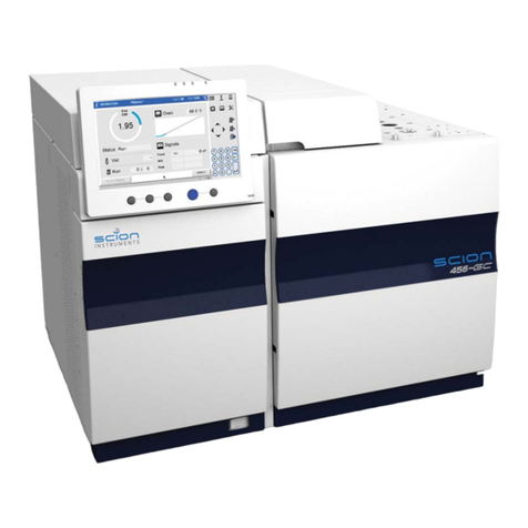
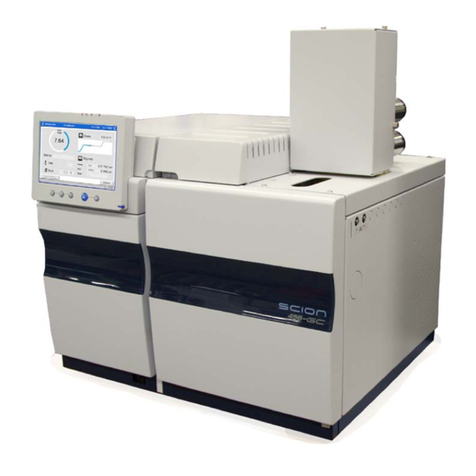
Scion Instruments 456-GC User manual

SCION Instruments HQ SCION Instruments NL BV
Suite 34, Livingston Business Centre, 4462, Goes,
Kirkton Road South, Livingston, Stanleyweg 4.
EH54 7FA, Scotland, UK. The Netherlands
Tel: +44 1506 300 200 Tel: +31 113 348 926
sales-[email protected] sales-[email protected]
www.scioninstruments.com www.scioninstruments.com
Revised February 2019
© 2015 Scion Instruments
Reference Manual
Transformer Gas Analyzer

Scion Instruments
Scion Instruments Transformer Gas Analyzer Reference Manual Page: 2
Section contents
INTRODUCTION ......................................................................................................................... 3
INSTRUMENT SPECIFICATIONS .......................................................................................... 4
INSTALLATION OF COLUMNS, FLOW AND PRESSURE SETTINGS .......................... 5
OPERATION ................................................................................................................................ 7
TROUBLE SHOOTING............................................................................................................... 9
STEP BY STEP...........................................................................................................................10

Scion Instruments
Scion Instruments Transformer Gas Analyzer Reference Manual Page: 3
INTRODUCTION
Certain faults in electrical transformers may result in the production of
gases, which remain dissolved in the transformer fluid. The transformer fluid
and insulating materials will break down into a few easily identifiable by-
products when subjected to fault conditions.
Identification and quantification of these gases can provide an early
indication of developing problems in the equipment.
ASTM methods D3613, D2945 and D3612 describe sampling, gas extraction
and analysis procedures respectively.
The components of interest in the extracted gas are typically hydrogen,
oxygen, nitrogen, carbon monoxide, carbon dioxide, methane, ethane,
ethylene and acetylene.
The Transformer Gas Analyzer Channel is an analytical tool principally
developed for the determination of these components.
The sample is simultaneously injected into two individual channels by
means of a
10 port gas sampling valve equipped with two sample loops. A molecular
sieve column separates the lighter gases like hydrogen, oxygen, nitrogen,
methane and carbon monoxide while a porous polymer column separates
the other carbon gases. A methanizer-FID combination ensures that the
carbon oxide gases are detected at low ppm levels.
For a real understanding of the flow scheme, see also the states of
operation in section 3 of this manual.
The instrument is tuned during Final Test to its proper settings. Do
not change any flow or pressure settings unless it is requested.

Scion Instruments
Scion Instruments Transformer Gas Analyzer Reference Manual Page: 4
INSTRUMENT SPECIFICATIONS
Every instrument is fully tested; the results of the tests, as well as the
methods used during these tests, are presented as part of this manual (refer
to section 1).
START UP
At initial START-UP as well as after a longer idle period,
follow the instructions below:
•
Connect all the gases to the instrument.
•
Switch the power on.
•
Load the appropriate method.
•
Check the flow settings.
•
Condition the system as described in this manual.
•
Do not make any changes to the methods.
•
The system is ready for injections.
For a new system there is no need to do any flow measurement or
flow tuning before power-up.
The instrument is tuned and tested in the Factory in Goes.

Scion Instruments
Scion Instruments Transformer Gas Analyzer Reference Manual Page: 5
INSTALLATION OF COLUMNS, FLOW AND PRESSURE SETTING
Tuning of the analyzer is only necessary in case new columns are
installed or after flow or pressure settings have been changed.
Before new columns may be installed, they need to be
preconditioned!!
Make sure, the instrument is connected to the minimum gas supply
conditions as indicated in the 456-GC pre-installation manual.
For more detailed information concerning the configuration of the
instrument, please, refer to the drawing section (section 6 of this manual).
The factory drawing indicates which flow and pressure controls are being
used. The drawing also outlines the way the analyzer channel has been
incorporated into the gas chromatograph.
Regularly check and replace filters maintaining the supply quality as
described in the pre installation requirements.
Replacement columns:
BRP2059 Molsieve 13X 45/60, 3ft * 1/8" Inert Steel
BRP2068 Hayesep N 80/100, 6ft * 1/8" Inert Steel
BRP2056 Flame out buffer (OV101 on GHP, 2ft * 1/8" Inert Steel)

Scion Instruments
Scion Instruments Transformer Gas Analyzer Reference Manual Page: 6
Tuning the TGA channel
Tuning is only necessary when new columns have to be installed or by
malfunctioning of the GC. Connect the columns according the flow
schematics given in Section 6 and adjust the pressures (if necessary) at an
oven temperature of 70°C.
Take very good care not to create any dead volume!
•Set valve 1 and 2 in the (-) position.
•Turn of all flows to the FID.
•While measuring the flow at the exit of the FID, adjust the H2flow for the
methanizer at 20 ml/min.
•Turn of the H2supply from the methanizer.
•Set the front EFC-24 flow (flow over the Molsieve column) until there is 30
ml/min Ar coming out the exit of the FID.
•Switch valve 2 to the (+) position. And set the middle EFC-24 flow (flow over
Delay and Hayesep column) until there is 30 ml/min Ar coming out the exit
of the FID.
•Adjust the digital manual flow controller for the reference TCD flow at 30
m/min.
•Open the H2supply.
•Program the method as given in the OPERATION section.
Check all connections for leakage. If big leaks are detected it
may advisable to repeat flow tuning.
After stabilization of the TCD and FID signal the system is ready for
determination of the optimal column selection time.
Inject a gas mixture with hydrogen, oxygen, nitrogen, methane and carbon
monoxide at the molecular sieve column. After elution of the CO peak, valve
2 can be switched in the (+) position for elution of the components from the
Hayesep column.

Scion Instruments
Scion Instruments Transformer Gas Analyzer Reference Manual Page: 7
OPERATION
Operational method is preloaded in the instrument.
Listed below is an example method; settings determining the application
may be different.
Sample delivery:
V1 (GSV)
V2 (CS)
Initial
-
-
0.1
+
-
3.0
+
+
9.9
-
-
Flow/Pressure:
Front EFC-24 (Ar):
Pressure (psi)
Hold (min)
Initial
27.5
10
Total Flow: 60 ml/min
Middle EFC-24 (Ar):
Pressure (psi)
Hold (min)
Initial
38.5
10
Total Flow: 60 ml/min
Column Oven:
Temp (ºC)
Rate (ºC/min)
Hold (min)
Total (min)
Initial
70
--
10
10
Valve oven:
Temp 100(ºC)
Methanizer oven:
Temp: 400 °C
Hydrogen flow: 20 ml/min
Detector (front TCD):
Temp: 200 ºC
Range: 0.05
Time cons: slow
Fila temp: 254 °C

Scion Instruments
Scion Instruments Transformer Gas Analyzer Reference Manual Page: 8
Fila max: 390 °C
Polarity: negative
DEFC 13:
Reference flow: 30 ml/min Ar
Detector (middle FID):
Temp: 300 ºC
Range: 12
Time constant: slow
Middle DEFC 11:
Make up: 0 ml/min (Ar)
Hydrogen: 10 ml/min
Air: 300 ml/min
This method is only valid in case the instrument is equipped with one
Transformer Gas Analyzer channel only.
Refer to section 1 for the actual method(s), whenever the instrument has
combined channels.
Never interrupt an analytical run. The complete cycle has to
finish!

Scion Instruments
Scion Instruments Transformer Gas Analyzer Reference Manual Page: 9
TROUBLE SHOOTING
For problems related to the basic hardware and electronics of the gas
chromatograph, as well as injectors and detectors, refer to the 456-GC user
reference manual.
In case of any analytical problem, it is always advised to record an analysis using a
reference sample. The result, including full details can be submitted to your local
Scion Instrument service department to judge performance.
Fig. 1 and fig. 2 show chromatograms of the FID and TCD tracks respectively. In
case of decreasing retention times of the Molecular Sieve column, this column
needs reconditioning. Conditioning needs to be done in a different oven under
nitrogen or helium at a temperature of 350 °C overnight.
Check the status of the humidity filter in case of conditioning is needed. The cause
might be saturation of this filter.
Fig. 1: FID chromatogram
Fig. 2: TCD chromatogram
Minutes
0.0 0.5 1.0 1.5 2.0 2.5 3.0 3.5 4.0 4.5 5.0 5.5 6.0 6.5 7.0 7.5 8.0 8.5 9.0 9.5
Volts
0.00
0.02
0.04
0.06
0.08
0.10
0.12
Volts
0.00
0.02
0.04
0.06
0.08
0.10
0.12
Channel A-- 3800 FID
none
Minutes
01 2
Volts
0.000
0.005
0.010
0.015
0.020
0.025
0.030
Volts
0.000
0.005
0.010
0.015
0.020
0.025
0.030
Channel A -- 3800 TCD
none
1
3
2
Legend
1) O2
2) CH4
3) CO
4) CO
5) CH4
6) CO2
7) C2H4
8) C2H6
9) C2H2
Legend
1) H2
2) O2
3) N2
4
1
2
5
6
7
8
9
3

Scion Instruments
Scion Instruments Transformer Gas Analyzer Reference Manual Page: 10
STEP BY STEP
Step by step drawings for the Transformer Gas Analyzer Channel

Scion Instruments
Scion Instruments Transformer Gas Analyzer Reference Manual Page: 11
Load Position: Valve -1, Valve -2

Scion Instruments
Scion Instruments Transformer Gas Analyzer Reference Manual Page: 12
Inject Position: Valve +1, Valve -2

Scion Instruments
Scion Instruments Transformer Gas Analyzer Reference Manual Page: 13
Backflush position: Valve +1, Valve +2
Other manuals for 456-GC
1
Table of contents
Other Scion Instruments Measuring Instrument manuals