manuals.online logo
Brands
  1. Home
  2. •
  3. Brands
  4. •
  5. Mastech
  6. •
  7. Measuring Instrument
  8. •
  9. Mastech MS2001 Assembly instructions

Mastech MS2001 Assembly instructions

01 02
03
04 05
OPERATOR'S
INSTRUCTION MANUAL
Safety Information
The di git al clam p met er has be en de signe d acc ordin g to IE C
1010 -1 an d IEC10 10- 2-032 c onc ernin g saf ety req uir ement s
for el ect rical m eas uring i nst rumen ts an d hand – he ld cu rrent
clam ps wi th over vol tage ca teg ory 100 0V CAT II 6 00V C AT III
and po llu tion 2.
Safety Symbols
Safety Precautions
DIGITAL CLAMP METER
Impo rta nt safe ty in forma tio n, refe r to th e
oper ati ng manu al.
Dang ero us volt age m ay be pre sen t.
Eart h gro und.
Doub le in sulat ion ( P rotec tio n class 1 000 V
CAT II 6 00V C AT III ).
The di git al clam p met er comp lie s with th e req uirem ent s of the
foll owi ng Euro pea n Commu nit y Direc tiv es: 89/ 336 /EEC ( El ec-
trom agn etic Co mpa tibil ity ) a nd 73/2 3/E EC ( Low Vol tag e ) as
amen ded b y 93/68 /EE C ( CE Mark ing ) .
Howe ver, e lectr ica l noise o r int ense el ect romag net ic fiel ds in
the vi cin ity of th e equ ipmen t may d istur b the m easur eme nt
circ uit .Meas uri ng inst rum ents wi ll al so resp ond t o unwan ted
sign als t hat may b e pre sent wi thi n the mea sur ement c irc uit.
User s sho uld exe rci se care a nd ta ke appr opr iate pr eca ution s
to avo id mi slead ing
Foll ow al l safet y and o perat ing i nstru cti ons to en sur e maxim um
pers ona l safet y dur ing the o per ation a nd to e nsure t he me ter is
used s afe ly and is k ept i n good op era ting co ndi tion.
• Read t hes e opera tin g instr uct ions th oro ughly a nd co mplet ely
befo re op erati ng yo ur mete r. Pay p artic ula r atten tio n to
WAR NIN GS , whi ch wi ll i nfo rm yo u of p ote nti al ly da nge ro us
proc edu res. The in str uctio ns in t hese wa rni ngs mus t be fo llowe d.
• Alwa ys in spect y our m eter an d tes t leads f or an y sign of
dama ge or a bnorm ali ty befo re ev ery use . If an y abnor mal
cond iti ons exi st (i .e. bro ken t est lea ds, c racke d cas es, dis pla y
not re adi ng, etc .), d o not att emp t to t ake a ny me asure men ts.
• Do not e xpo se the in str ument t o dir ect sun lig ht, ext rem e
temp era ture or m ois ture.
• Neve r gro und you rse lf when t aki ng elec tri cal mea sur ement s.
Do not t ouc h expos ed me tal pip es, o utlet s, fi xture s, et c., whi ch
migh t be at g round p ote ntial . Kee p your bo dy is olate d fro m
grou nd by u sing dr y clo thing ; rub ber sho es, r ubber m at, o r any
appr ove d insul ati ng mate ria l.
• You al way s ar e car efu l wh en wo rki ng w ith v olt ag es ab ove 6 0V
dc or 30 V ac rm s. Keep f ing ers beh ind t he prob e bar riers w hil e
meas uri ng.
• Neve r use t he mete r to me asure v olt ages th at mi ght exc eed
the ma xim um allo wab le inpu t val ue of any f unc tion.
• Neve r tou ch expo sed w iring , con necti ons o r any liv e cir cuit
when a tte mptin g to ta ke meas ure ments .
• Befo re op ening t he ca se, alw ays d iscon nec t test le ads f rom all
ener giz ed circ uit s.
• Neve r use t he mete r unl ess the b ack c over is i n pla ce and
fast ene d compl ete ly.
• Do not u se ab rasiv es or s olven ts on t he mete r. To cle an it u sing
a damp c lot h and mil d det ergen t onl y.
Maintenance
• Qual ifi ed and tr ain ed serv ice t echni cia ns shou ld on ly perf orm
cali bra tion an d rep air of th e met er.
• Do not a tte mpt cal ibr ation o r ser vice un les s train ed an d anoth er
pers on ca pable o f ren derin g fir st aid an d res uscit ati on is pre sen t.
General Description
The met er is a handh eld 3 1/2 dig ital clam p meter for
measu ring DC and AC v oltage, AC c urrent, R esistan ce,
Diode a nd Contin uity Test wi th batter y operate d.
“ ” jack
This is t he positi ve input te rminal fo r ohms and di ode.
Conne ction is ma de to it usin g the red tes t lead.
Power S witch
A push pus h switch is u sed to turn t he meter on o r off.
Tri gger
Press t he lever to o pen the tra nsforme r jaws. Whe n the
lever i s release d, the jaws w ill close a gain.
Ω
8
Front Panel Description
Tra nsfo rme r jaws
Pick up t he AC curren t flowing t hrough th e conduct or.
Hold bu tton
When th is button i s pushed, t he displa y will keep t he
last re ading and “ ” s ymbol wil l appear on t he LCD
until p ushing it a gain.
Rotar y switch
This sw itch is use d to select f unction s and desir ed
range s.
Back li ght
To use this f unction , press the L IGHT but ton. When t his
butto n is pushed , the Back li ght of disp lay is on. Aft er
about 3 5 s econds, t he Back lig ht is self- off. Th e Back
light i s on again, j ust push th is button o nce.
1
2
3
4
5
6
7
H
Displ ay
3 1/2 dig it, 7 segme nt, 16mm hi gh, LCD.
“V” jac k
This is p ositive i nput term inal for VO LT me asu reme nts
conne ction is ma de to it usin g the red tes t lead.
“COM” j ack
This is n egative ( g round ) inp ut termin al for all
measu rement mo des excep t current . Connect ion is
made to i t using the b lack test l ead.
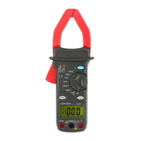
CLAMP METER LAY O U T
9
10
DIGITAL CLAMP METER DIGITAL CLAMP METER DIGITAL CLAMP METER DIGITAL CLAMP METER DIGITAL CLAMP METER
1
3
2
4
5
5
7
8
9
10
°C
Ω
V
A
KHz
220 200
~
1000A
~
200A
750V
~
1000V
1000Ω
2000Ω
200Ω
ONOFF LIGHT
CLAMP METER
DC
AC
~
ΩCOM V
1000V CAT ll
600V CAT lll
MAX 1000A~
1000V CAT ll
600V CAT lll
HOLD
°C
Ω
V
A
KHz
220 200
~
1000A
~
200A
750V
~
1000V
1000Ω
2000Ω
200Ω
ONOFF LIGHT
CLAMP METER
DC
AC
~
ΩCOM V
1000V CAT ll
600V CAT lll
MAX 1000A~
1000V CAT ll
600V CAT lll
HOLD
1108 09 1006 07 11
HYS006621
NOTE:
3. Conn ect test le ads acros s the resis tor to be mea sured
and rea d LCD displ ay.
4. If the r esi stan ce being me asured is c onnecte d to a
circu it, t urn off power an d dischar ge all capa citors
befor e applyin g test prob es.
1. If the r esi stan ce being me asured ex ceeds the
maxim um va lue of t he range se lected or t he input is
not con nected, a n overran ge indica tion “1”w ill be
displ ayed.
2. When c hecking i n-circu it resist ance, be su re the
circu it un der te st ha s all po wer remov ed and that a ll
capac itors hav e been disc harged fu lly.
Audib le Co ntin uit y Test
1. Conn ect red tes t lead to “ ” jac k, bl ack te st le ad to
“COM” j ack .
2. Set ra nge switc h to “ ” po siti on.
3. Conn ect test le ads to two po ints of cir cuit to be te sted.
If cont inu ity ex ist s, bui lt- in buz zer will so und.
Diode Test
1. Conn ect the red t est lead to “ ” j ack a nd the b lac k
test le ad to t he “CO M” ja ck (Th e pol arit y of re d lead
is posi tive “+”. ).
2. Set th e rotary sw itc h at “ ” pos iti on.
3. Conn ect the red t est lead to t he anode of t he diode to
be test ed an d the bl ack test le ad to the cat hode of the
diode . The appr ox. forwa rd voltag e drop of the d iode
will be d isplaye d. If the con nection i s reverse d, only
figur e “1” w ill be s hown.
Specifications
Accur acy is spec ified for a p eriod of on e year afte r
calib ration an d at 18° C to 28°C(64°F t o 82°F) with r elative
humid ity to 80%.
Gener al
Maximum voltage
between terminals
and earth ground
CAT II 1000V and CAT III 600V
Display LCD,1999 counts, updates 2-3/ sec.
“-”displayed for negative polarity.
Only figure “1” on the display.
42mm (Max conductor size)
9V battery, NEDA 1604 6F22 006P.
“ ”Appears on the display.
0 to 40°C
-10°C to 50°C
0.1×specified accuracy) / °C
(<18°C or >28°C)
Temperature coefficient
Storage temperature
Operating Environment
Low battery indication
Power
Polarity indication
Overrange Indication
Jaw opening capability
Altitude
Size
Weight
2000m
250mm×99mm×43mm
Approx.460g.
DC Volt age
Range Resolution Accuracy
1000V 1V ±1.0% of rdg ±2 digits
Input I mpedanc e: 10MΩ
AC Volt age
Range Resolution Accuracy
750V 1V ±1.0% of rdg ±5 digits
Input I mpedanc e: 10MΩ
Frequ ency rang e: 40Hz to 40 0Hz. Resp onse: Ave rage
respo nding, ca librate d in rms. of a si ne wave.
Range Resolution Accuracy
20A 0.01A ± 2.0% of rdg ±5 digits
AC Curr ent
200A
1000A
0.1A
1A
± 2.0% of rdg ±5 digits
± 2.0% of rdg ±7 digits
Overl oad Prote ction: 12 00A for 60 sec onds maxi mum.
Frequ ency rang e: 50Hz to 60 Hz.
Resis tance
Range Resolution Accuracy
200Ω0.1Ω± 1.0% of rdg ± 3 digits
2000Ω1Ω± 1.0% of rdg ± 3 digits
Replacing The Battery
WARNING
Conti nui ty
Range Description
If cont inuity ex ists (abo ut less tha n 20Ω),
built -in buzze r will soun d.
Befor e attempt ing to open t he case of ba ttery, al ways
be sure t hat test le ads have be en discon nected fr om
measu rement ci rcuits. C lose case a nd tighte n screws
compl etely bef ore using t he meter to a void elec trical
shock h azard.
If “ ”app ear s on dis play, it in dicates t hat the bat tery
shoul d be replac ed. Use the f ollowin g procedu re to
repla cing the ba ttery:
1. Disc onnect te st leads fr om any live s ource and r emove
the tes t lea ds fro m the i nput t erm inal s of th e mete r.
Push th e POW ER swi tch t o OFF,
2. The b attery co ver is secu red to the bo ttom case b y a
screw. U sing a scre wdriver, r emove the s crew from
the bat ter y cove r and r emov e the batte ry cover.
3. Remo ve batter y and repla ce with a new e quivale nt 9
volt ba tte ry.
4. Repl ace the bat tery cove r and reins tall the sc rew.
Accessories
• Opera tor's ins tructio n manual
• Set of te st le ads
• Gift bo x
• 9 volt ba ttery. NE DA 1604 6F22 0 06P type .
CAUTION:
Using t his appli ance in an en vironme nt with a str ong
radia ted radio -freque ncy elect romagne tic field
(appr oximate ly 3V/m), m ay influe nce its mea suring
accur acy. The m easu rin g resu lt ca n be str ong ly
devia ting from t he actual v alue.
Operating Instructions
DC Volt age Measu rement
1. Conn ect the red t est lead to t he “V” jack a nd the blac k
lead to t he “C OM” ja ck.
2. Set ro tary swit ch at desir ed 1000V po sition.
3. Conn ect test le ads acros s the sourc e or load bei ng
measu red.
4. Read v oltage va lue on the LC D display a long with t he
polar ity of the re d lead conn ection.
AC Volt age Measu rement
1. Conn ect the red t est lead to “ V~” jack an d the black
test le ad to t he “CO M” ja ck.
2. Set th e rot ary sw itc h at des ired 750V ~ positio n.
3. Conn ect test le ads acros s the sourc e or load bei ng
measu red .
4. Read v oltage va lue on the LC D display.
AC Curr ent Measu rement
1. Set th e rot ary sw itc h at des ired A~ posi tion.
2. Pres s the trigg er to open tr ansform er jaw and to c lamp
one con ductor on ly, makin g sure that t he jaw is fir mly
close d around th e conduct or.
3. Read c urrent va lue on LCD di splay.
4. When o nly the fig ure “1” is di splayed , it indica tes
overr ange situ ation and t he higher r ange has to b e
selec ted.
Resis tance Mea suremen t
1. Conn ect the red t est lead to “ ” j ack a nd bla ck
test le ad to t he “CO M” ja ck (Th e pol arit y of re d lead
is posi tiv e “+”) .
2. Set th e rot ary sw itc h at des ired“ ”ra nge posit ion.
Ω
Ω
Ω
Ω
DIGITAL CLAMP METER DIGITAL CLAMP METER DIGITAL CLAMP METER DIGITAL CLAMP METER DIGITAL CLAMP METER DIGITAL CLAMP METER

Other manuals for MS2001

1

Other Mastech Measuring Instrument manuals

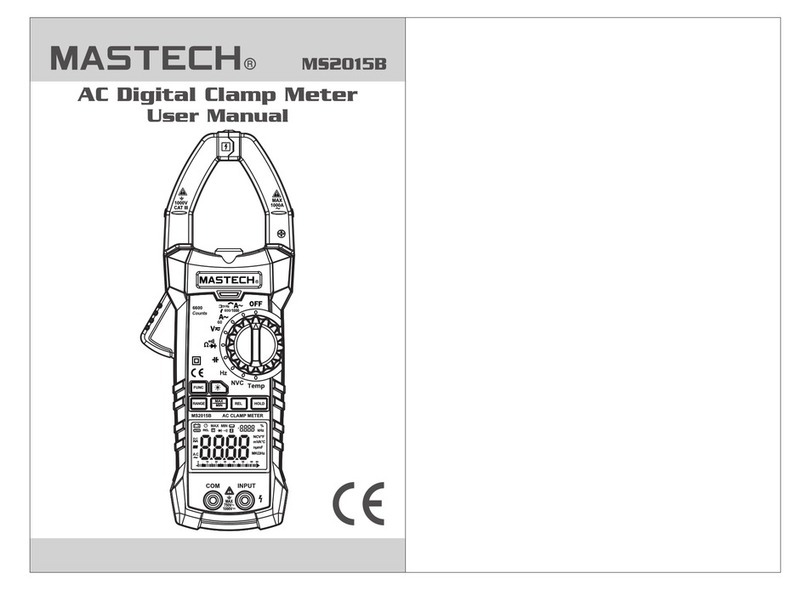
Mastech MS20108 User manual

Mastech

Mastech MS20108 User manual

Mastech MS6252A User manual

Mastech

Mastech MS6252A User manual

Mastech MS2301 User manual

Mastech

Mastech MS2301 User manual

Mastech MS2030B User manual

Mastech

Mastech MS2030B User manual

Mastech MS2025A User manual

Mastech

Mastech MS2025A User manual

Mastech MS6700 User manual

Mastech

Mastech MS6700 User manual

Mastech MS6508 User manual

Mastech

Mastech MS6508 User manual

Mastech MS6503 User manual

Mastech

Mastech MS6503 User manual

Mastech MS8239D User manual

Mastech

Mastech MS8239D User manual

Mastech MS2026R Assembly instructions

Mastech

Mastech MS2026R Assembly instructions

Mastech MS2015B User manual

Mastech

Mastech MS2015B User manual

Mastech MS8238A User manual

Mastech

Mastech MS8238A User manual

Mastech MS2140A User manual

Mastech

Mastech MS2140A User manual

Mastech MS5908C User manual

Mastech

Mastech MS5908C User manual

Mastech MS20006 User manual

Mastech

Mastech MS20006 User manual

Mastech MS2108 User manual

Mastech

Mastech MS2108 User manual

Mastech ms6231 User manual

Mastech

Mastech ms6231 User manual

Mastech MS2201 User manual

Mastech

Mastech MS2201 User manual

Mastech MS2016A User manual

Mastech

Mastech MS2016A User manual

Mastech M266F Assembly instructions

Mastech

Mastech M266F Assembly instructions

Mastech MS6252B User manual

Mastech

Mastech MS6252B User manual

Mastech MS6700 User manual

Mastech

Mastech MS6700 User manual

Mastech MS8240D User manual

Mastech

Mastech MS8240D User manual

Mastech MS8212A User manual

Mastech

Mastech MS8212A User manual

Popular Measuring Instrument manuals by other brands

MadMan CLD2 user manual

MadMan

MadMan CLD2 user manual

Kimo DS200 user manual

Kimo

Kimo DS200 user manual

Georg Fischer Piping Systems MSA 340 instruction manual

Georg Fischer Piping Systems

Georg Fischer Piping Systems MSA 340 instruction manual

Cateye VELO WIRELESS Plus CC-VT210W quick start

Cateye

Cateye VELO WIRELESS Plus CC-VT210W quick start

wurth 0715 53 188 user manual

wurth

wurth 0715 53 188 user manual

ALAT UJI MS6612 user manual

ALAT UJI

ALAT UJI MS6612 user manual

HP 1660CS-Series user guide

HP

HP 1660CS-Series user guide

Keysight E5063A Configuration guide

Keysight

Keysight E5063A Configuration guide

Rhopoint Instruments IQ Flex 20 operating instructions

Rhopoint Instruments

Rhopoint Instruments IQ Flex 20 operating instructions

GREISINGER GLF 100 RW operating manual

GREISINGER

GREISINGER GLF 100 RW operating manual

Arbiter Systems 931A Application note

Arbiter Systems

Arbiter Systems 931A Application note

palintest Pooltest 25 manual

palintest

palintest Pooltest 25 manual

Fidelity Electronics 19e Operation manual

Fidelity Electronics

Fidelity Electronics 19e Operation manual

Fluke 1730 Calibration manual

Fluke

Fluke 1730 Calibration manual

Hioki PW3365-20 quick start guide

Hioki

Hioki PW3365-20 quick start guide

Rohde & Schwarz R&S DVMS1 Getting started

Rohde & Schwarz

Rohde & Schwarz R&S DVMS1 Getting started

Moons' MS502 user manual

Moons'

Moons' MS502 user manual

SMS SHZV operating instructions

SMS

SMS SHZV operating instructions

manuals.online logo
manuals.online logoBrands
  • About & Mission
  • Contact us
  • Privacy Policy
  • Terms and Conditions

Copyright 2025 Manuals.Online. All Rights Reserved.