Infineon Lite SBC Series User manual


Other manuals for Lite SBC Series
2
This manual suits for next models
1
Table of contents
Other Infineon Microcontroller manuals
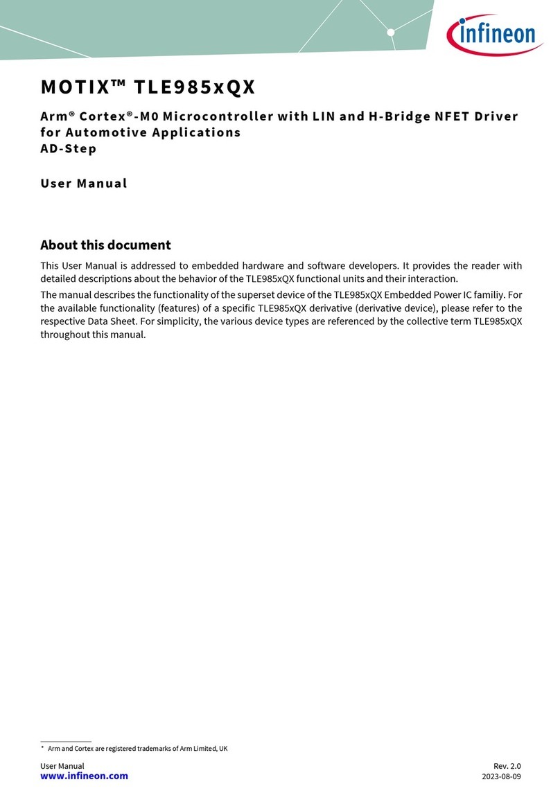
Infineon
Infineon MOTIX TLE985xQX User manual
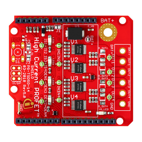
Infineon
Infineon PROFET+2 12V Arduino Shield User manual
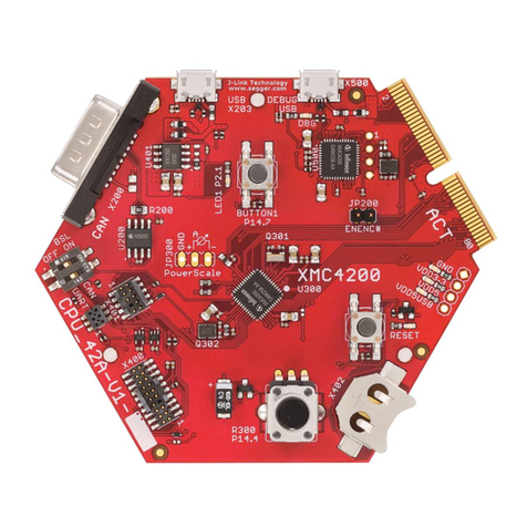
Infineon
Infineon XMC4000 series User guide

Infineon
Infineon CY4613 User manual
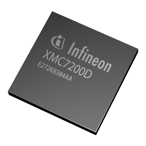
Infineon
Infineon XMC7000 Series Guide
Infineon
Infineon XC886CLM User manual
Infineon
Infineon XMC1400 User manual

Infineon
Infineon XMC4000 series User manual

Infineon
Infineon Cypress PSoC 4500S Pioneer Kit User manual
Infineon
Infineon CY8CKIT-062-WIFI-BT User manual
Infineon
Infineon AIROC CYW20829 User manual

Infineon
Infineon PSoC 4100S Max pioneer kit User manual
Infineon
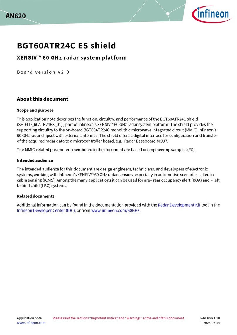
Infineon BGT60ATR24C Installation and operating instructions
Infineon
Infineon XC164CM Series User manual
Infineon
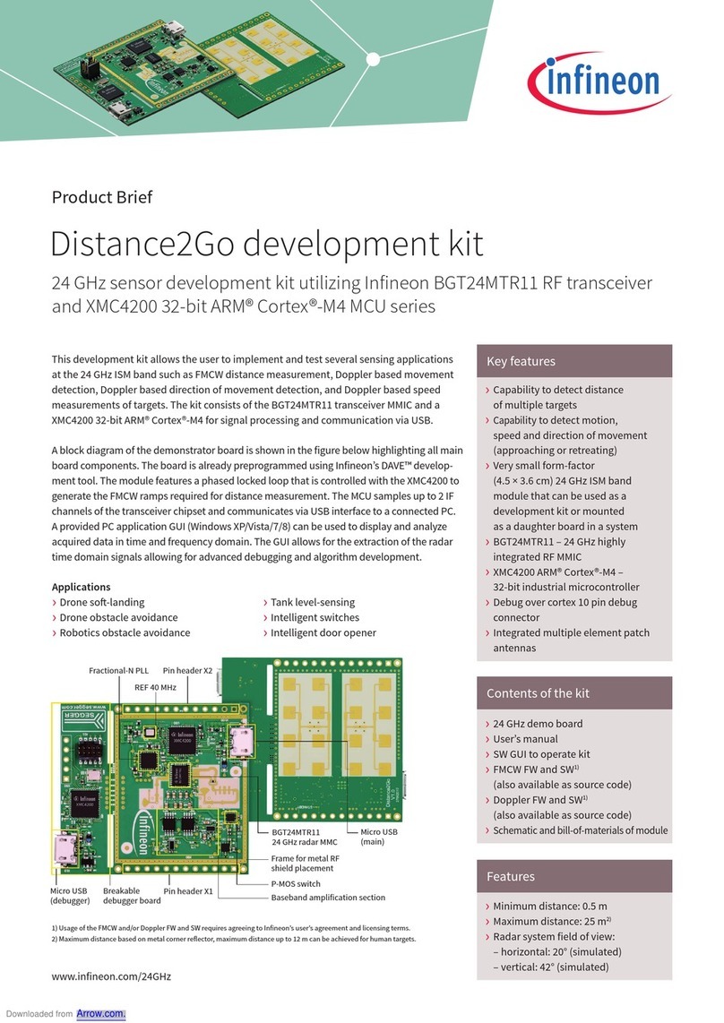
Infineon Distance2Go Reference guide
Infineon
Infineon XMC Series User guide
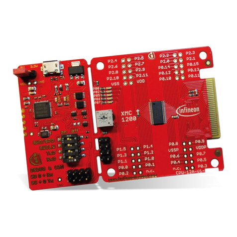
Infineon
Infineon XMC1000 User manual
Infineon
Infineon Traveo II Entry Family Starter Kit User manual
Infineon
Infineon TC1796 Installation and operating instructions
Infineon
Infineon PSoC 6 User manual
Popular Microcontroller manuals by other brands
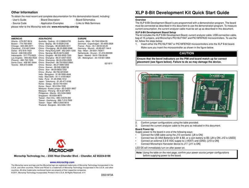
Microchip Technology
Microchip Technology XLP quick start guide
Freescale Semiconductor
Freescale Semiconductor MC9S12DJ128E user guide
Renesas
Renesas RL78/I1A user manual
Fujitsu
Fujitsu F2MC-8L Series Hardware manual
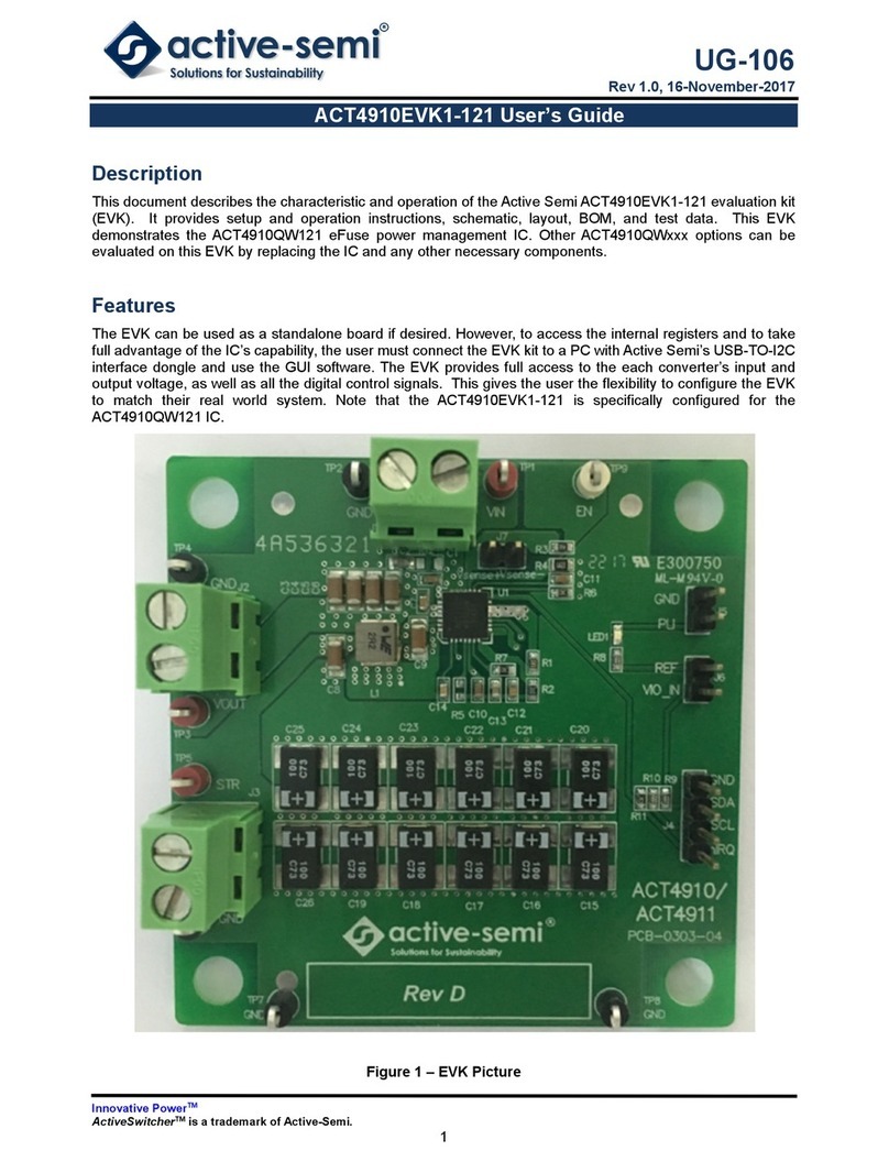
Active-semi
Active-semi ACT4910EVK1-121 user guide

Microchip Technology
Microchip Technology Microsemi Hello FPGA Libero Design user guide


