Scireq flexivent User manual

USER MANUAL
.
INTEGRATED PLATFORM.
FOR PRECLINICAL.
PULMONARY RESEARCH.


WELCOME TO THE FLEXIVENT FX
Congratulations, and thank you for selecting the
flexiVent
! The
flexiVent
FX combines the most
accurate, detailed and reproducible measurements of respiratory mechanics with flexible and
efficient experimentation management.
The
flexiVent
FX operates with
flexiWare
software in a system designed for
mechanical ventilation and life support
execution of measurement manoeuvres including the Forced Oscillation Technique
(FOT)
management and storage of acquired raw data
data analysis & model fitting
visualization, storage and export of results, and
maintenance of experimental records in electronic format.
This user manual contains important information and should be studied in detail before
operating the
flexiVent
FX. However, this manual is not intended to be a complete guide of the
flexiWare
software. For detailed information about using and configuring the
flexiWare
software, please refer tothe
flexiWare
user manual.


flexiVent
User Manual version 6.2.
(Document No: FV-FXUM)
Revised July 31, 2014
© SCIREQ Scientific Respiratory Equipment Inc., 1997–2014.
All rights reserved. This manual may not be reproduced or duplicated in print or any other media, including
electronic storage and transmission, without prior written permission from SCIREQ Scientific Respiratory
Equipment, Inc.
Aero
g
en and Aeroneb are re
g
istered trademarks of Aero
g
en, Inc., Galwa
y
, Ireland.
The information contained in this manual is believed to be accurate at the time of print.
However, SCIREQ Scientific Respiratory Equipment Inc. does not offer any warranties, express
or implied, for the content of the manual and the use of all related products. The license and
operating conditions apply.
SCIREQ Scientific Respiratory Equipment Inc.
6600 rue St-Urbain, Suite 300
Montreal, Quebec, Canada H2S 3G8
P. 514-286-1429
P. 877-5-SCIREQ (toll-free in Canada and USA; 877-572-4737)
F. 514-286-1627
www.scireq.com

iv
SAFETY CONSIDERATIONS
WARNINGS
The
flexiVent
is not intended for use with human subjects.
If you use anaesthetic gas and/or aerosols, take precautions to ensure that the expired
gas/aerosol does not escape into the room air.
Ensure proper evacuation and control of potentially harmful substances being introduced
into the system to protect the user(s).
Disengage the motor lock before connecting a power source.
Do not attempt to open the base unit cover while the instrument is running; there is a
danger of moving parts.
When carrying or moving the
flexiVent
, always ensure that the device is kept horizontal and
supported by two hands underneath the unit.
The power cord used should comply with local standards.
Use only the power supply provided by SCIREQ with the
flexiVent
system.

v
Only gases may be introduced through the air intake (e.g. room air, non-flammable mixed
gas, inhaled anesthesia). Introduction of other substances through the air/gas intake, e.g.
particulates or aerosol, may damage the module’s piston.
Always unscrew the piston rod before attempting to remove the module from the base unit.
Handle the module carefully. Avoid straining or bending the piston rod.
Clean the expiratory valve only. Do not attempt to clean the refill or inspiratory valves.
Do not attempt to clean or dry the expiratory line while an FX adapter is in place in the
module. Also, do not attempt to clean or dry the expiratory line while outside of an
experimentation session. Attempting to clean or dry the expiratory line with the valve close
will damage the module.
Do not use abrasive or corrosive detergents or mechanical cleaning aids.
Do not dismantle the module or base unit to attempt to clean it.
Do not use abrasive or sharp tools to clean the nebulizer unit.
Do not autoclave the Aeroneb controller or cables.
Do not immerse the Aeroneb controller or cables in water.

vi
Avoid removing the nebulizer from the mount while a subject is attached. If it is necessary
(e.g. for cleaning), do so quickly and immediately replace the nebulizer or use a cap to close
the ventilator circuit.
When you are using and handling the
flexiVent
, always observe all of the cautionary notes
included in this manual. SCIREQ is not liable for damage or injury resulting from misuse of this
product.
LIST OF SYMBOLS
The following table describes the electrical and safety symbols that may be displayed on the
flexiVent
FX. The safety symbols may also appear throughout this manual and other product
support documents.
SYMBOL DESCRIPTION
Direct current
Alternating current
Caution, risk of electric shock
Caution; closely observe all cautionary statements to prevent
equipment damage and ensure operator safety
Power button
Ethernet network cable connection port

vii
SYMBOL DESCRIPTION
Auxiliary channels
Synchronization port (in)
Synchronization port (out)
Power supply connection
Intake/Inspiratory line
Exhaust/Expiratory line
Inappropriate for disposal in general waste
Aluminum components; please recycle as appropriate
Internal magnet

viii
TABLE OF CONTENTS
1Introduction....................................................................................................................................................................11
1.1Intended Use ........................................................................................................................................................... 11
1.2UnitWise Platform &
flexiWare
.................................................................................................................... 12
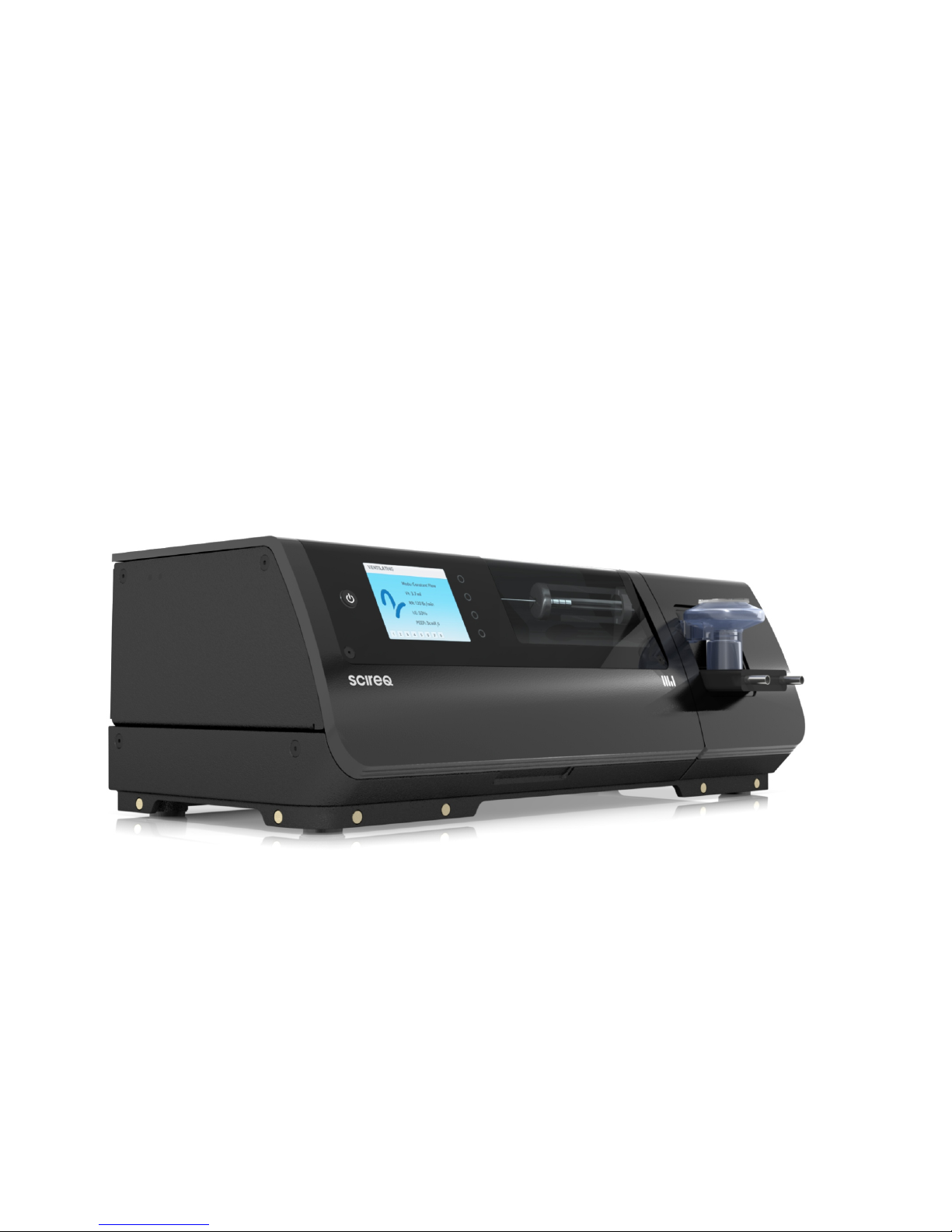
1.3
flexiVent
FX
System Overview.....................................................................................................................16
1.4Theory of Operation ............................................................................................................................................17
2Set up & Installation.................................................................................................................................................25
2.1Selecting a Location...........................................................................................................................................25
2.2Preparing for Installation...........................................................................................................................25
2.3Placing the System....................................................................................................................................... 28
2.4Connecting the Components................................................................................................................... 28
2.5Opening the
flexiVent
protective cover .............................................................................................33
2.6Working with an Alternate Module....................................................................................................... 34
2.7Configuring
flexiWare
.................................................................................................................................38
3Getting Started ......................................................................................................................................................... 39
4Accessories ................................................................................................................................................................. 50
4.1UNIT Transducers...............................................................................................................................................50

ix
4.2Nebulizer............................................................................................................................................................54
4.3Calibration Accessories..............................................................................................................................57
4.4Hardware Extension for Negative Pressure Forced Expirations (NPFE)..........................58
4.5Multi-subject Extension (MSX) ..............................................................................................................60
5Cleaning, Decontamination and Maintenance.............................................................................................61
5.1Cylinder.....................................................................................................................................................................61
5.2Cleaning flow pathways and Valves.....................................................................................................62
5.3FX Adapter and Y-tubing...........................................................................................................................66
5.4External Surfaces..........................................................................................................................................66
5.5Aeroneb Nebulizer........................................................................................................................................ 67
5.6Annual Cleaning and Maintenance........................................................................................................68
5.7Repackaging, Transport and Storage..................................................................................................69
5.8Replacement Components....................................................................................................................... 74
Appendix A: Technical Specifications.........................................................................................................................76

x

11
1INTRODUCTION
The
flexiVent
FX is a
UnitWise
instrument most often used for assessment of respiratory
mechanics in pre-clinical research. Your system is customized to your research application and
may be enhanced as new products are released.
1.1 INTENDED USE
At its core, the
flexiVent
is a computer-controlled piston ventilator that allows you control over
ventilation parameters. To perform an assessment of respiratory mechanics, ventilation is
momentarily suspended and a pre-defined volume waveform is applied by the piston. The data
collected during the manoeuvre are analyzed by the software, which reports measurements of
mechanics. The computer control of the piston and precision with which data are collected
generates accurate, reproducible measurements of respiratory mechanics.
The
flexiVent
FX is designed for full mechanics assessments in subjects weighing
approximately 8 g to 1 kg. It may be used for ventilation and mechanics measurements from
small amplitude manoeuvres in subjects weighing approximately 8 g to 5 kg. Additional details
are available in Table A-2.
If you intend to use the
flexiVent
outside typical operating conditions explained in this user
manual, please contact SCIREQ Technical Support for additional instructions and
documentation.
The
flexiVent
is not intended for use with human subjects.

12
1.2 UNITWISE PLATFORM &
FLEXIWARE
The
flexiVent
FX is built on the second generation
UnitWise
platform, a fully digital, data
acquisition and control architecture designed to be operated by
flexiWare
software. For
additional details on
flexiWare
refer to the
flexiWare
user manual.
FIGURE 1-1: UNITWISE PLATFORM
The
flexiWare
/
UnitWise
platform consists of a variety of different components that are
optimized for their individual tasks and communicate digitally with each other, as illustrated in
Figure 1-1. This section provides an overview of the different platform components to permit
users a better understanding of the interplay between the different system components.

13
1.2.1 WORKSTATIONS
The
UnitWise
platform uses standard Ethernet connectivity as the backbone to connect the
high-level components of a
UnitWise
data acquisition and experimentation environment. The
list of high-level components includes the individual
UnitWise
instruments (see section 1.2.2),
experimentation and review workstations (both running
flexiWare
), and the database server on
which data may be stored in a central location.
In the simplest scenario, a single stand-alone computer can serve as experimentation
workstation, review workstation and database server. On the other hand, the
UnitWise
/
flexiWare
architecture permits distributed multi-client environments where data may
be simultaneously collected from several parallel workstations into a central database, allowing
study directors to observe the evolution of the experiment in real time from the comfort of
their office.
1.2.2 INSTRUMENTS & SYSTEMS
In
UnitWise
terminology, “instruments” are compact laboratory instrumentation devices that
possess both an Ethernet connection and several ports for Universal Intelligent Transducers
(UNITs). Recent
UnitWise
instruments also feature a display and local user interface on the
device. Instruments serve as the central building blocks of
UnitWise
data acquisition systems
and perform the large majority of all real-time data acquisition, control and automation
functions.
In
UnitWise
terminology, “systems” comprise one or more instruments as well as a variety of
UNITs selected according to the application at hand, connected together in such a way that the
specific data acquisition and control needs of this application are met. Every
UnitWise
system
must contain one primary instrument, and may contain one or more secondary instruments. The
secondary instruments are controlled by the primary instrument, permitting phase-locked data
acquisition systems with a virtually unlimited number of channels.

14
FIGURE 1-2: UNIVERSAL INTELLIGENT TRANSDUCER (UNIT) ARCHITECTURE
1.2.3 PORTS, UNITS & CHANNELS
UnitWise
instruments typically possess eight ports, each of which may be occupied by one
Universal Intelligent Transducer (UNIT) without further adapters, amplifiers or pods, so that any
UNIT can fit into and be recognized by any instrument port (see Figure 1-2).
Every UNIT contains between one and four sensor elements or other input/output channels,
each permitting the measurement or modification of a physical property. To optimize the signal-
to-noise ratios, all input signals are digitized right in the UNIT. A small micro-controller (μC)

15
contained in every UNIT scales and linearizes the signals and performs self-tests and local
control functions. The controller also retains calibration and identification details that are
communicated digitally to the instrument and the host software to log the system configuration
and assert its integrity.
A common example for a simple UNIT is shown in UNIT A in Figure 1-2. This UNIT has a single
analog input channel to measure a signal from a single sensing element and communicate it to
the instrument and the software. A precision differential pressure transducer such as model
UT-DPD-02 is an example of this type of UNIT.
UNIT B in Figure 1-2 provides an example of local low-level servo control. This UNIT combines an
analog input channel with an embedded actuator that has the ability to manipulate the attribute
being measured in order to simultaneously collect the actual measurement and push it towards
a desired value as provided by the instrument and/or the software. An example for this type of
UNIT would be a temperature-controlled water bath.
UNIT C in Figure 1-2 provides a further example of the platform’s flexibility as it shows 3 analog
input channels communicating measurements to the software while a fourth digital output
channel is used to allow the software to switch or send synchronization signals to outside
instruments.
1.2.4 INTEGRATED SYSTEMS
In
UnitWise
terminology, some SCIREQ products are referred to as “integrated systems” since
they contain both an instrument and one or more UNITs in a common package. For example, a
flexiVent
FX has all features of a
UnitWise
instrument (Ethernet, ports and embedded display)
but also possesses several internal ports to measure and control volume displacement,
pressures and valve states. Integrated systems such as the
flexiVent
typically feature a limited
number of external (auxiliary) ports for accessories, and their port count can be further
extended by adding a secondary instrument (see section 1.2.2).
Some integrated systems offer functionality that goes above and beyond the capabilities of a
standard
UnitWise
data acquisition system (e.g. mechanical ventilation for the
flexiVent
, pump
profiles for the
inExpose
). When working with an integrated system such as the
inExpose
or the

16
flexiVent
, menus and commands are automatically configured in the software such that you
have complete access to your instrument’s functionality. The instrument-specific configuration
is controlled by
flexiWare
licensing, SDMs and template mechanisms. It does not require any
additional steps or configuration settings during operation. All commands necessary for your
application are available for your use, following setup and installation.
1.3
FLEXIVENT
FX
SYSTEM OVERVIEW
The
flexiVent
FX is composed of two main parts: the base unit and a module. The base unit
includes the following:
a computer-controlled linear actuator;
an optical position sensor;
a processing platform (controller);
a base plate with a protective enclosure ;
a module connection platform; and
an embedded user interface.
A module is comprised of the following:
a precision piston-cylinder set;
three computer-controlled valves;
pressure transducers;
a micro-processor; and
air flow pathways and connections.
For additional details, see section 1.2.

17
1.4 THEORY OF OPERATION
As is mentioned in section 1.1, the
flexiVent
is a computer controlled piston ventilator. The
computer control afforded by
flexiWare
software makes the
flexiVent
versatile because you
control the parameters of the ventilation and measurement manoeuvres that it executes. Its
design adds to its versatility in part because it may be used with a range of subject sizes, but
also because it allows for the integration of a variety of accessories and hardware extensions,
which includes both SCIREQ products and third-party products.
1.4.1 RESPIRATORY MECHANICS
Generally speaking, mechanics is the relationship of objects and the forces that act upon them.
Respiratory mechanics is a way to quantify the airway constriction and stiffness of the lungs
through relationships between pressure, volume and flow using mathematical models.
1.4.2 FORCED OSCILLATION TECHNIQUE
Measurement manoeuvres executed by the
flexiVent
are referred to as perturbations. During a
perturbation, an iso-volume ventilator compartment is established when the valves within the
module close to the outside environment. The ventilator compartment consists of the subjects
respiratory system, the cylinder, pathways outside the module (e.g. Y-tubing) and pathways
within the module (e.g. from the cylinder to the Y-tubing). Once the valves are closed, the
perturbation, or Forced Oscillation, is applied to the ventilator compartment through movement
of the piston (see Figure 1-3). The signals generated during the perturbation are used to
calculate parameters of respiratory mechanics that help to quantify acute and/or chronic
disease-related changes to the lungs.

18
FIGURE 1-3: VALVE CONFIGURATION DURING A PERTURBATION
There are six families of perturbations. A description of each follows. The properties (e.g.
duration, maximum pressure) for the perturbations are established in the
flexiWare
software.
For detailed information about perturbation properties, refer to the
flexiWare
user manual.
TABLE 1-1: STANDARD FLEXIVENT PERTURBATIONS
NAME DESCRIPTION SAMPLE
Deep
Inflation
Deep inflation of the subject's
lungs to a pressure of 30 cmH20
(or other user-specified value)
followed by a breath hold of
typically a few seconds.
Table of contents
Popular Medical Equipment manuals by other brands

Agilent Technologies
Agilent Technologies Heartstream FR2 user guide

Arthrex
Arthrex SynergyID AR-3200-0025 Instructions for use

Compex
Compex FUSE manual

mychway
mychway MS-2183 user manual

Alpine HC
Alpine HC Opera Signature Profiling Bed Installation guide and technical specifications

Juzo
Juzo JuzoFlex Manu Xtra manual