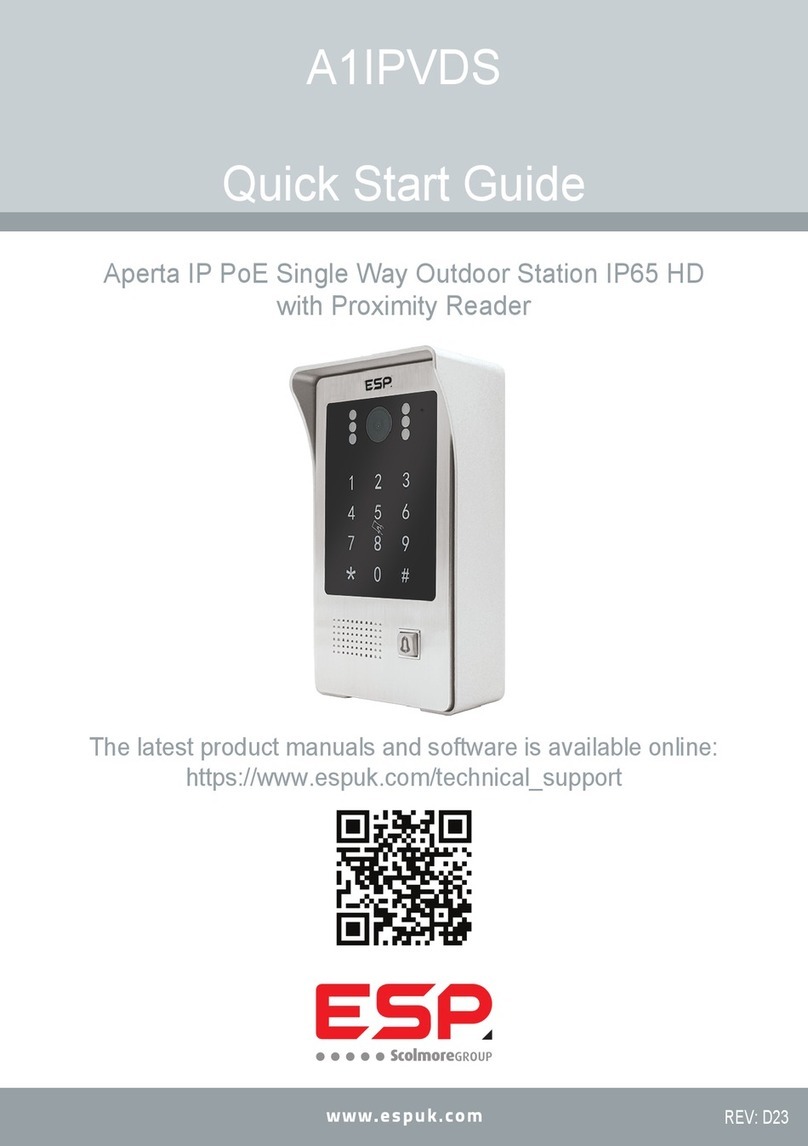
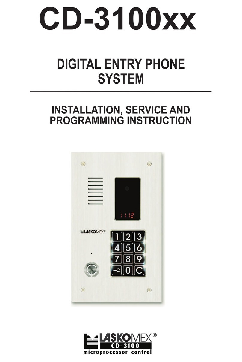
Scolmore ESP Aperta A1IPVDS Installation instructions

A1IPVDS
Full Manual
Aperta IP PoE Single Way Outdoor Station IP65 HD
with Proximity Reader

2
1. Appearance Introduction
2. Parameters
Camera Sensor:
Camera sensor automatically switches between day and night modes
Viewing Angle:
(Horizontal) 110°
Resolution:
1.0MP HD
LED Night Vision:
White Light LED (120°)
Operating Voltage:
Input DC: +12V to +15V, 48-52V PoE (IEEE802.3af)
Operating Current:
Standby: <150mA @DC15V, 2.25W
Operating: <300mA @DC15V, 4.5W
Operating Environment
Ambient Temperature: -20°C to 50 °C
Relative Humidity: ≤95%
3. Function Introduction
This product features that includes;
• PIN Code
• RFID Card/Fobs (13.56MHz)
• Door Entry
• Video & Audio Intercom
1. This product utilises both RFID and PIN Code unlock functions. In this manual, the Digital Keypad will be used for any and all administrator Mode
operations). The RFID card(s) will be used for managing any and all User Card/Fob Operations
2. The white light LEDs and backlight LEDs contain a light sensing function. In day light conditions the white light LEDs & backlight LEDs will not
illuminate. In night conditions both the white light LEDs & backlight LEDs will illuminate. .
1 White Light LED
2 Camera
3 Photo Resistor
4 Digit Button
5 Speaker
6 Call Button
7RFID Area
8 Microphone
9DC Input
10 PoE Interface
11 Lock Control Integrated Interface (J1)
12 RS 485 Interface (J3)
No. Location Denition Colour Function
J1 1 NO12V+ Red Constant DC12V (+)
2 NC Orange Normally Closed
3 COM Green Common
4 NO Yellow Normally Open
5 CTL Brown Exit button
6 DET White Door Sensor
7 GND Black Ground (-)
No. Location Denition Function
J3 1 RS 485B 485B Data
2 RS 486A 485A Data
3 GND Ground

3
4. Administator Operations
4.1 Default Settings:
Default Administrator Passcode is 666666.
Default Public Unlock Passcode is 123456.
The default door opening method is RFID.
The default unlock time is 2 seconds.
Safe mode is turned o by default.
The public unlock passcode is enabled by default
4.2 Entering Administator Mode
* [ADMINISTATOR PIN] #
When in Administration mode, press *, then type in the administration passcode, followed by #.
If the A1IPVDS bleeps twice & the call button ashes slowly, this means it has been entered successfully.
If Administation mode is not successfully entered; the A1IPVDS will bleep 4 times.
If a timeout of 30 seconds occur the A1IPVDS will bleep 3 times, meaning the A1IPVDS has exited administation mode.
Press * during any of the following settings will return to the previous level or will exit out of the Administation Mode.
4.2.1 Modify Administration Passcode, Public Unlock Passcode & how to reset the A1IPVDS
4.2.1.1 Public Unlock Passcode
0 11 # [New Unlock Passcode] # [Conrm New Unlock Passcode] #
When in Administration mode, press 0 (the call button will start to rapidly ash), then press 11 #, followed by the desired 6 digit Passcode and then #.
You will then reenter the desired 6 digit passcode to conrm the passcode and nally press # to end to sequence.
If the A1IPVDS bleeps twice, this means it has been set successfully.
4.2.1.2 How to use the Public Unlock Passcode
Type in the Public Unlock Passcode and press #.
EX. 123456#
4.2.1.3 Adminstrator Passcode
0 77 # [New Admin Passcode] # [Conrm New Admin Passcode] #
When in Administration mode, press 0 (the call button will start to rapidly ash), then press 11 #, followed by the desired 6 digit Passcode and then #.
You will then reenter the desired 6 digit passcode to conrm the passcode and nally press # to end to sequence.
If the A1IPVDS bleeps twice, this means it has been set successfully.
4.2.1.4 Reset
There are 2 ways to reset an A1IPVDS back to factory defaults;
4.2.1.4.1 Using the Keypad
When in Administration Mode, press 0 (the call button will rapidly ash), followed by 99 # (the A1IPVDS will bleep once), and the A1IPVDS will be
restored to factory default.
4.2.1.4.2 Using the Call button
When in standby, press and hold the call button for 60 seconds, until the A1IPVDS bleeps and it reboots. The A1IPVDS will be restored to factory
defaults.

4
4.2.2 Setup Unlock Mode
4.2.2.1 Card Only Unlock
3 00 #
When in Administration Mode, press 3 (the call button will rapidly ash), followed by 00 #, the A1IPVDS will bleep twice to conrm Card Only Unlock
has been set.
4.2.2.2 Card or Passcode Unlock
3 01 #
When in Administration Mode, press 3 (the call button will rapidly ash), followed by 01 #, the A1IPVDS will bleep twice to conrm Card or Passcode
Unlock has been set.
4.2.2.3 Card and Passcode Unlock
3 02 #
When in Administration Mode, press 3 (the call button will rapidly ash), followed by 02 #, the A1IPVDS will bleep twice to conrm Card and
Passcode Unlock has been set.
4.2.3 Adjusting the Unlock Time of Relay
4 XYZ #
When in Administration Mode, press 4 (the call button will rapidly ash), followed by the time you want to set as a 3 digit format and then press #, the
A1IPVDS will bleep twice to conrm the unlock time has been set.
4.2.3.1 Example 1; 2 Second Unlock Time
When in Administration Mode, press 4 (the call button will rapidly ash), followed by 002 #, the A1IPVDS will bleep twice to conrm the Unlock time
has been set to 2 Seconds.
4.2.3.2 Example 2; Latching Unlock Time
When in Administration Mode, press 4 (the call button will rapidly ash), followed by 000 #, the A1IPVDS will bleep twice to conrm the Unlock time
has been set to latching Mode.
4.2.4 Safety Mode Setup
4.2.4.1 Turn o Safety Mode
5 00 #
When in Administration Mode, press 5 (the call button will rapidly ash), followed by 00 #, the A1IPVDS will bleep twice to conrm that Safety Mode
has been turned o.
4.2.4.2 Locked Safety Mode
5 01 #
Locked Safety Mode works by if within a 5 minute period that if an incorrect and/or passcode is entered 10 times, the A1IPVDS will be locked, and the
A1IPVDS’s internal buzzer will sound for 1 minute, with the call light ashing, and the indoor monitor will start monitoring.
When in Administration Mode, press 5 (the call button will rapidly ash), followed by 01 #, the A1IPVDS will bleep twice to conrm that Safety Mode
has been turned o.
4.2.4.3 Alarm Safety Mode
5 02 #
Alarm Safety Mode works by if within a 5 minute period that if an incorrect and/or passcode is entered 10 times, the A1IPVDS’s internal buzzer will
sound for 1 minute, with the call light ashing, and the indoor monitor will start monitoring.
When in Administration Mode, press 5 (the call button will rapidly ash), followed by 01 #, the A1IPVDS will bleep twice to conrm that Safety Mode
has been turned o.

5
4.2.5 Public Unlock Password Enablement
4.2.5.1 Disabling the Public Unlock Passcode
6 00 #
When in Administration Mode, press 6 (the call button will rapidly ash), followed by 00 #, the A1IPVDS will bleep twice to conrm that the Public
Unlock Passcode has been turned o.
4.2.5.2 Enabling the Public Unlock Passcode
6 01 #
When in Administration Mode, press 6 (the call button will rapidly ash), followed by 01 #, the A1IPVDS will bleep twice to conrm that the Public
Unlock Passcode has been turned on.
4.2.6 Add a Master Card
Only 2 master cards can be hosted on a single A1IPVDS, these 2 master cards can be used to unlock the door just like a user card can.
7 #
When in Administration Mode, press 7 (the call button will rapidly ash), followed by #, the A1IPVDS will bleep twice to conrm that it is in master card
adding mode.
You will then present 2 cards, which the rst card will become the Master Add card, and the second the Master Delete card (and the A1IPVDS will bleep
twice for each successfully added card) ,and nally the A1IPVDS will exit from Administration mode automatically.
5. Managing User Card(s)
With each A1IPVDS’s comes a factory set 3 add cards & 3 remove cards. If a user was to lose these, only one of each can then be set. For adding new
master cards please refer to 3.2.6
1. Master Card(s) cannot be deleted, it can only be replaced by a new master card
2. Master Card(s) and User Card(s) set on one A1IPVDS cannot unlock other A1IPVDS’s unless those same cards are programmed onto the other
desired A1IPVDS’s
5.1 Adding User Cards
When in Standby Mode, swipe the Add Master card 3 times within 15 seconds, the call button will rapidly ash to indicate that the add user mode has
been entered successfully.
Swipe the unregistered card in the RFID read area, when the A1IPVDS bleep twice, this means this card has been added successfully.
Once all desired user cards have been added, swipe the Master Add Card to exit (The call button will stop ashing, and will now return to the standard
operation of constant illumination). If there are no operations after a 30 second period, it will automatically exit.
5.2 Delete User Cards
5.2.1 Part Delete
When in Standby Mode, swipe the Delete Master card 3 times within 15 seconds, the call button will rapidly ash to indicate that the delete user mode
has been entered successfully.
Swipe the unregistered card in the RFID read area, when the A1IPVDS bleep twice, this means this card has been deleted successfully.
Once all desired user cards have been deleted, swipe the Master Delete Card to exit (The call button will stop ashing, and will now return to the
standard operation of constant illumination). If there are no operations after a 30 second period, it will automatically exit.
5.2.2 Full Delete
When in Standby Mode, swipe the Delete Master card 3 times within 15 seconds, the call button will rapidly ash to indicate that the delete user mode
has been entered successfully.
Swipe the Add Master Card in the RFID read area, the A1IPVDS will bleep 7 times and return to standby mode.

6
6. User Operations
6.1 Modify User Passcode by Card
* [Present User Card] [Current User Passcode] # [New User Passcode] # [New User Passcode] #
Note: Default User Passcode is 0000, and cannot be used to unlock the door. This Passcode must be modied to use the User Passcode
When in Standby Mode, press *, swipe the desired User card that you want to change the user code for, type in the current User Code (default is 0000),
press #, then type in the new desired 4 digit Passcode press #, and then reenter this same 4 digit Passcode and nally press #. The A1IPVDS will
bleep once to indicate the User Passcode has been successfully modied.
6.2 User RFID Card Unlock
Present Valid RFID User/Master Card
Note: section 3.2.2.1 needs enabling for this mode to operate.
In Standby Mode swipe a valid registered card at the RFID area, the output relays for door locks will switch, and the A1IPVDS will say “The door is
open, please come in”.
6.3 RFID Card or User Passcode Unlock
Note: section 3.2.2.2 needs enabling for this mode to operate.
6.3.1 Unlocking via RFID Card
Present Valid RFID User/Master Card
In Standby Mode swipe a valid registered card at the RFID area, the output relays for door locks will switch, and the A1IPVDS will say “The door is
open, please come in”.
6.3.2 Unlocking via Passcode
[4 Digit Passcode] #
In Standby Mode type in the 4 digit Passcode and press #, the output relays for door locks will switch, and the A1IPVDS will say “The door is open,
please come in”.
6.4 RFID Card And User Passcode Unlock
[Present Valid RFID User/Master Card] [Input 4 Digit Passcode] #
Note: section 3.2.2.3 needs enabling for this mode to operate.
In Standby Mode swipe a valid registered card at the RFID area and then type in the 4 Digit User Passcode and press #, the output relays for door locks
will switch, and the A1IPVDS will say “The door is open, please come in”.

7
Reed Switch
Note:
When using number 2 or 3 connection types, the purple line is not needed.
Note:
EVBPSBB (with optional battery backup feature) sold separately
7. Wiring Diagrams
Connection Diagrams
A1IPVDS Connections Diagram
Lock Connections
Alternative power connections
GND
12V
485A
485B
GND
RS485
NO12V+
NC
COM
NO
CTL
DET
GND
(Red)
(Orange)
(Green)
(Yellow)
(Brown)
(White)
(Black)
IP/PoE connection
Fail Secure Lock (+)
Video Door Station
Lock Connections
Exit button
Sensor Ground

8
30mm
15V
PSU
15V
PSU
System Wiring Diagrams
Installation Diagrams
Flush Mounting Dimensions

9
8. Mounting Diagrams Accessories
• A1IPVDS 1 Pc
• Plastic Rawl Screws 4 Pcs
• Installation Screws 6 Pcs
• Quick Start Guide 1 Pc
• 3 Pin Cable (0.1m) 1 Pc
• 7 Pin Cable (1m) 1 Pc
• 2 Pin Cable (1m) 1 Pc
• Master Add Fob 3 Pcs
• Master Delete Fob 3 Pcs
• User Fob 4 Pcs
9. Installation
A1IPVDS
Quick Start Guide
The latest product manuals and software is available online:
https://www.espuk.com/technical_support
REV: G23
Aperta IP PoE Single Way Outdoor Station IP65 HD
with Proximity Reader

Contact Details
Elite Security Products UK, Unit 7 Target Park, Shawbank Road, Lakeside, Redditch, Worcestershire, B98 8YN
Registered in England, Company Registration Number: 02769392, VAT Registration: GB614686525
For more product information please visit www.espuk.com
E&OE - Errors and Omissions Excepted. K23
Table of contents
Other Scolmore Intercom System manuals
