Scotchman GAA-500-90 CNC DT20 User manual

PRINTED OCTOBER 2020
MODEL
GAA-500-90 CNC DT20
AUTO UPCUT
COLD SAW
WWW.SCOTCHMAN.COM

TABLE OF CONTENTS
1.0 INTRODUCTION
1.1 Legislation applicable to the planning and construction of the machine.
1.2 Warranty
2.0 GENERAL MACHINE DATA
2.1 Machine identification data.
2.2 Technical data.
2.3 Electrical data.
2.4 Noise level.
3.0 INDICATIONS REGARDING TRANSPORT AND STORAGE
4.0 INSTRUCTIONS FOR ANCHORING AND SERVICE START-UP
4.1 Anchoring instructions.
4.2 Power supply connection.
4.3 Instructions regarding blade installation.
4.4 Cutting coolant.
4.5 Pneumatic oil.
5.0 INSTRUCTIONS FOR USE
5.1 Proper and improper use.
5.2 Function of the operating mechanisms.
5.3 Manual mode.
5.4 Auto mode.
5.5 General rules and safety checks.
6.0 RECOMMENDATIONS AND MAINTENANCE
6.1 Type and frequency of inspections.
6.2 Qualified personnel for maintenance and repair work.
6.3 Possible breakdowns.
6.4 Manufacturer recommendations.
7.0 DRAWINGS AND SCHEMATICS
8.0 MAIN FRAME ASSEMBLY
9.0 SHUTTLE FEED SYSTEM
10 . OPTIONAL CHIP COLLECTOR - WIRE LOCATIONS
1. INTRODUCTION
This instruction manual has been made in compliance with the requirements of the Legislation according
to the Machine directive 2006/42/CEE and its subsequent amendments.
The instruction manual represents an integral part of the machine. It must be consulted before, during
and after the machine is put into service, as well as whenever it is considered necessary, thereby
respecting the content in each and everyone of its parts.
This is the only way in which the fundamental objectives that have been established on the basis of this
manual will be achieved, such as accident prevention and making optimal use of the machine features.
Within the framework of this manual, all aspects regarding safety and accident prevention on the job
Page 2
2
3
3
4
4
4
4
4
5
5
5
5
6
6
6
7
7
7
9
9
12
12
12
14
14
15
16
22
24
26

Page 3
while using the machine have been considered in every detail, herein highlighting the information that is
of greatest interest to the user.
ATTENTION! Before installing the machine, read this manual carefully. The manual must be kept
throughout the life of the machine, so that it is easy to find, if necessary. In the event that the used
machine is sold, the machine shall be sold together with this manual. In the event that the machine is
scrapped, the identification plate and any other document supplied with the same must be
destroyed.
1.1 LEGISLATION
(Applicable to the planning and construction of the machine.)
EN-12100-1 Machine Safety. Basic concepts, general design principles.
EN-12100-2 Machine Safety. Basic concepts, general design principles.
EN-13857 Safety distances to prevent dangerous zones from being reached by the upper extremities.
EN-60204/1 Electrical equipment of industrial machines.
EN-13850 Machine Safety; emergency stop equipment.
2006/42/CE On "Machine Safety"
93/68/CE On the CE Marking (amendment).
73/23/CE On "Safety of Electrical Material".
2004/108/CEE On "Electromagnetic Compatibility".
1.2 WARRANTY
Scotchman Industries, Inc. will, within 2 years of date of purchase, replace F.O.B. the factory or
refund the purchase price for any goods which are defective in materials or workmanship and, at the
seller’s option, returns the defective goods, freight and delivery prepaid, to the seller, which shall be the
buyer’s sole and exclusive remedy for defective goods.
Hydraulic and electrical components are subject to their respective manufacturer’s warranties.
This warranty does not apply to machines or components which have been altered, changed or
modified in any way or subjected to abusive or abnormal use, inadequate maintenance or lubrication
or subjected to use beyond the seller’s recommended capacities and specifications.
In no event shall seller be liable for labor costs expended on such goods or consequential damages.
Seller shall not be liable to purchaser or any other person for loss or damage directly or indirectly
arising from the use of the goods or from any other cause.
No officer, employee or agent of the seller is authorized to make any oral representations or warranty of
fitness or to waive any of the foregoing terms of sale and none shall be binding on the seller.
Any electrical changes made to the standard machine to comply with local electrical codes must be paid
by the purchaser.
As we constantly strive to improve our products, we reserve the right to make changes without
notification.

Page 4
2. GENERAL INFORMATION
2.1 MACHINE IDENTIFICATION DATA
Model: GAA - 500 - 90° CNC DT20
Serial number:
Manufacturing year:
NOTE: In order to request spare parts, whether covered by the warranty or not, always indicate the
model and serial number of the machine; as well as the name of the part and the code that appears
in the last chapter of the parts exploded views.
2.2 TECHNICAL DATA
2.3 ELECTRICAL DATA
2.4 NOISE LEVEL
At a distance of 60cm RUNNING OFF-LOAD 68 Db (A) Leq
MACHINING A 70 X 50 PROFILE 108 Db (A) Leq
ATTENTION: When working with the machine, use individual hearing protection equipment.
Characteristics Dimension
Three phase motor 4 HP 230/400 V
Motor speed 3,000 RPM
Interior ∅of blade 50mm (2")
Maximum ∅of saw blade 500mm (20")
Maximum cutting height 170mm (6.8")
Feeder travel 700mm (28")
MULTIPLE ADVANCE
Air consumption 20 litres (5.2 gallons)/minute
Pneumatic hold-down clamps 6 (3 horizontal & 3 vertical)
Lubrication system Pneumatic, by sprayer
Dimensions 1950 x 1200 x 970
(height of working surface)
Weight 520 kgs (1,430 lbs)
Power supply Motor power Total consumption
220 V Three phase 1.5 Kw/2 HP 17 A
380 V Three phase 1.5 Kw/2 HP 12 A

Page 5
3. INDICATIONS REGARDING TRANSPORT/STORAGE
The machine is delivered on a pallet in order to be transported by forklift.
Store in the vertical position.
Do not stack.
If the machine remains stored for a long period of time, periodically lubricate it.
Do not expose to the elements.
The packaging is made of properly designed and sized wood and it is also supplied wrapped in plastic.
CAUTION: Do not improperly dispose of the packaging. Send this material to be recycled or
disposed of in accordance with all legislation in force.
4.0 INSTRUCTIONS FOR ANCHORING & SERVICE START-UP
4.1 ANCHORING INSTRUCTIONS
Ensure that the machine has not suffered any damage during transport by making an initial visual
inspection. If damage is observed, advise the manufacturer immediately.
The machine must be installed on a firm and level surface in order to thus reduce vibrations during
operation and so that the machine operates within the parameters established by the manufacturer.
4.2 POWER SUPPLY CONNECTION
Verify that the power supply voltage corresponds to the voltage indicated on the specifications plate of
the machine. Connect the cable to the power supply, using a plug that is appropriate for the
characteristics of the same, thereby respecting the color codes.
Once the machine is connected, verify that the motor rotation agrees with the direction of the saw blade
teeth (rotation to the right). If the motor rotation was not correct, change the two phases of the motor.
Then, check the rotation again.
The pneumatic connection must be made to the supply system, using a tube that is appropriate for the
spigot of the machine. Adjust the pressure at the filtering group.
ATTENTION! The pneumatic working pressure must be between 6 and 7 atm.

Page 6
4.3 BLADE INSTALLATION
In order to install the blade, disconnect the power to the machine (deactivate the main switch) and press
the EMERGENCY STOP BUTTON. Access the machine shaft through the sheet metal front, where the
cutting oil sprayer is located. Lock the shaft, using the 12 ∅rod that is provided with the tools, and
loosen the blade nut.
ATTENTION! Assure that the blade is adapted for this machine. (Diameter of the axis 50mm.)
DANGER! After changing the blade, put the sheet metal front back on.
4.4 CUTTING COOLANT
In order to fill the machine with cutting coolant, open the reservoir and fill with PURE,
NON-EMULSIFIABLE CUTTING OIL. (VISCOSITY ISO VG 16-32 cST 40°C)
4.5 PNEUMATIC OIL
Both the oil-pneumatic converters and the filter group lubricator must be filled with ISO VG 32
VISCOSITY PNEUMATIC OIL. If none is available, use hydraulic oil HLP 32.

Page 7
5. INSTRUCTIONS FOR USE
5.1 PROPER AND IMPROPER USE
This is an automatic cut-off machine, especially designed for cutting aluminum profiles. The use of the
machine for cutting other materials is hereby prohibited. Such use may cause damage to the machine and
put the health and safety of the worker at risk.
DANGER! We are not responsible for any possible accident caused by the failure to comply with the
aforementioned.
5.2 FUNCTION OF THE OPERATING MECHANISMS
1. Blue push button: To re-arm machine.
2. Operating mode selector: MANUAL - AUTOMATIC.
3. Green push button: Automatic cycle start.
4. Black push button: Hold down feeder clamp operation.
5. Black push button: Hold down machine clamp operation.
6. Lift protective shield.
7. Blade raise advance regulator.
8. Green push button: Blade raise.
9. Emergency button with interlock. It stops the machine completely.
10. Red push button: Automatic cycle stop.
11. Saw blade on-off: ON, green colored symbol I; OFF, red O.
12. Touch screen 5, 6".
Page 8
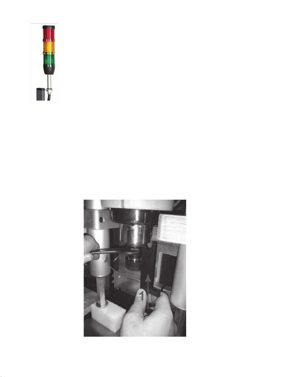
Signal lamps: Red: emergency.
Orange: Machine working in automatic cycle.
Green: Power supplied to the machine.
The machine is provided with one simple collet chucks with axial compensation for drill and tap.
To change the collet chuck:

Page 9
5.3 MANUAL MODE
With the operating mode switch in the MANUAL MODE, the operator can activate the hold down
clamps, the feeder gripper and the saw blade. We recommend that very high feed rate for the saw
blade or high feed rate on the shuttle feed not be used as this would greatly reduce the duration of
the blade and the quality of the cut. The feeder can also be operated for maintenance purposes in
this mode.
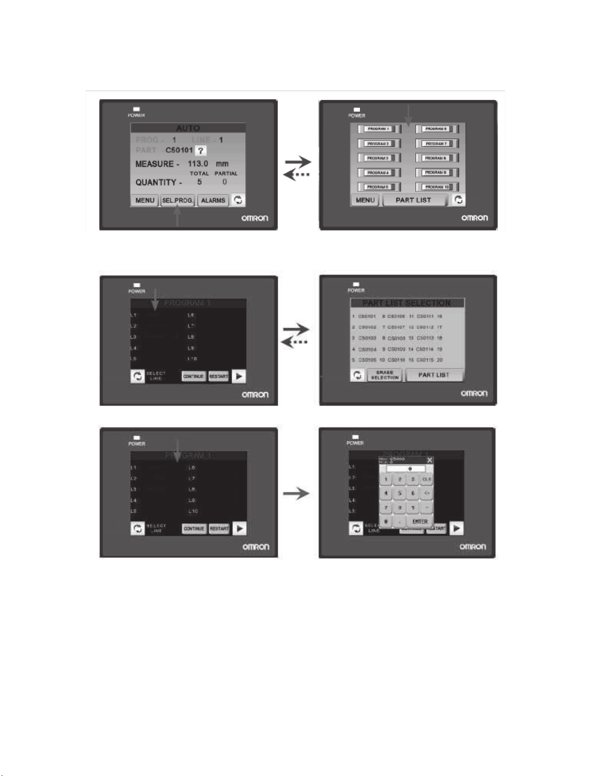
5.4 AUTO MODE
In the auto mode, you can program the part list and the programs of work. To program the part list,
use the following steps:
With the arrows
1 and 2, we can
select the
number of parts
to program. It
is possible to
program the
total length
and six
drilling
positions.
Page 10
TO CREATE, TO MODIFY AND TO EXECUTE A PROGRAM OF WORK:
1. Select the program of work.
2. Select the part list and the number of pieces.
If you don’t program code of piece or number of pieces, the program is finished.

Page 11
3. To execute the program:
A - To select line of beginning.
B - To continue the program in the last line in execution.
C - To execute the program from the first line.
When the machine is prepared for the execution of the program, follow the steps below:
1. Adjust the desired height of the cut, using the travel end stop at the right of the machine.
2. Position the machine hold-down clamps and the feeder gripper close enough to the material so that
they do not travel more than 5 millimeters (2/10 of an inch).
It is important that the horizontal hold-down clamp of the feeder gripper is a maximum of 5mm
from the material. If not, it will not allow the machine to be turned.
3. Position the bar over the feeder so that it passes by about 10mm (4/10 of an inch) from the saw blade
groove.
4. Fasten the material by operating the hold-down clamps of the feeder gripper.
5. Start the working cycle by pressing the START button.
The machine will stop automatically when the material is finished, the stop button is pressed, the
alarm is produced or when the program is finished. During the work of the machine, we can see
the measures of the part in execution.
Page 12
5.5 GENERAL RULES AND SAFETY CHECKS
Before using the machine, check the efficiency and perfect operation of all safety devices and check
that the moving parts of the machine are not blocked, that there are no damaged parts and that all
machine components are positioned and work correctly.
All safety devices must be kept in working order.
DO NOT operate this machine without the protective shield in position.
ALWAYS wear gloves and protective eyewear.
ALWAYS wear regulation work clothes that are not loose fitting and are fastened.
Before operating the machine, the operator must ensure that all tools used for maintenance or
adjustment have been removed.
In the event of a fire, use powder extinguishers and disconnect the machine from the electric system.
6.0 RECOMMENDATIONS AND MAINTENANCE
6.1 TYPE AND FREQUENCY OF INSPECTIONS
The operator’s knowledge of the machine is one of the best ways of daily control of any possible problem.
If any failure is detected, work must be stopped and qualified personnel must be informed immediately.
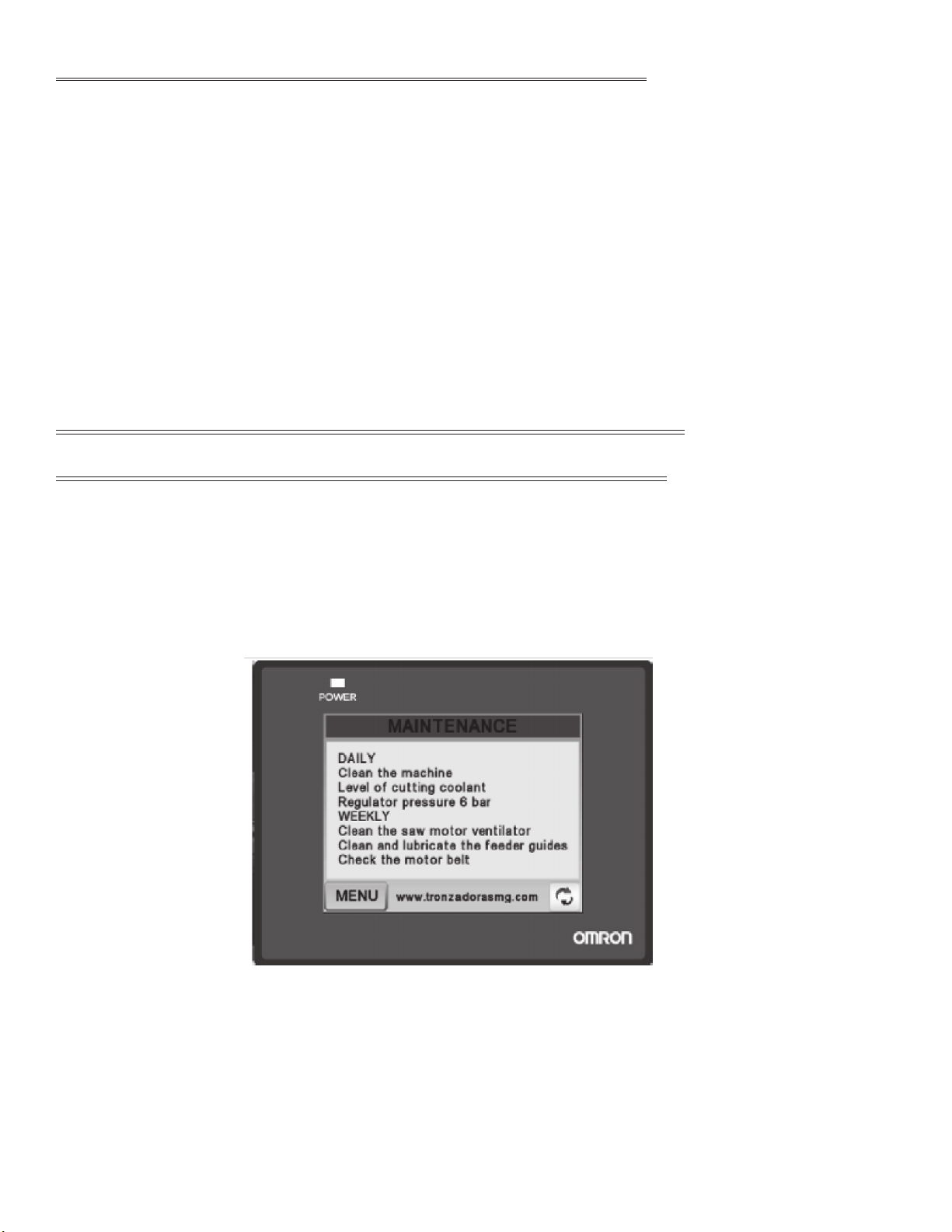
NOTE: ALWAYS CLEAN THE MACHINE AND THE WORK AREA AT THE END OF THE
WORKDAY.
Page 13
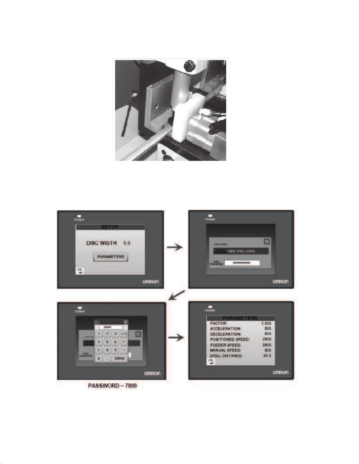
ATTENTION: Every eighty hours LUBRICATE - 2 strokes - KLUBER ISOFLEX NBU 15.
In the SETUP menu, we can modify the parameters of the machine.
The password 7890 may be used by qualified personnel only.

Page 14
6.2 QUALIFIED PERSONNEL FOR MAINTENANCE/REPAIR
All repairs shall be made exclusively by qualified personnel; thereby, always using original
replacement parts. If not, the machine may be damaged or the user may be injured.
The maintenance and cleaning of the machine must not be neglected. The life of the machine
and its optimal operation depend on it considerably.
6.3 POSSIBLE BREAKDOWNS
NONE OF THE MACHINE COMPONENTS WORK.
Check that there is voltage at the input and output of the main switch.
Check the control circuit fuse.
Check the condition of the transformer.
THE FEEDER DOES NOT WORK CORRECTLY.
Check the status of all end-of-travel stops and the positioning of same.
Check the condition of SERVO DRIVE.
Check the condition of the PLC and the voltage on the line itself (24 VDC).
THE SHIELD RAISED INDICATOR DOES NOT TURN OFF.
Ensure that the PLC is not receiving a signal at input ch103. If it is, check the detector located
on the shield cylinder.
THE BLADE DOES NOT RAISE CORRECTLY.
Check the cylinder and regulator.
Check the pressure at the filter regulator.
Check that the advance may be too high.
Check the "raise blade" push buttons.
THE FEEDER DOES NOT MOVE CORRECTLY.
Check the feeder guides.
Check the ball-screw.
Check that the advance may be too high.

Page 15
6.4 MANUFACTURER’S RECOMMENDATIONS
In the event that the machine is broken down or the saw blades must be replaced, place a padlock
on the protection switch and place the keys under the care of qualified personnel.
Before working on any electrical devices, disconnect the plug from the power supply.
If extension cords are used, ensure that the cable has the appropriate cross-section for the power
of the machine.
Whenever any part has to be replaced, use an original replacement part and endeavor to use the
oil recommended by the manufacturer.
NOTE: IN CASE OF ANY DOUBT OR PROBLEM, DO NOT HESITATE TO CONSULT THE
MANUFACTURER.
ATTENTION: THE MANUFACTURER GUARANTEES THE SUPPLY OF EACH ONE OF THE
PARTS OR COMPONENTS FOR AT LEAST THREE YEARS FROM THE MANUFACTURING
DATE OF THE MACHINE.
ATTENTION: THE MANUFACTURER IS NOT RESPONSIBLE FOR BREAKDOWNS
CAUSED DUE TO THE IMPROPER USE OF THE MACHINE.

Page 16
7.0 DRAWINGS AND SCHEMATICS

Page 17

Page 18

Page 19

Page 20
Table of contents
Other Scotchman Industrial Equipment manuals

Scotchman
Scotchman CPO-315-RFA-BL User manual

Scotchman
Scotchman DO-150-24M User manual

Scotchman
Scotchman PRESSPRO 66 User manual

Scotchman
Scotchman IRONWORKER 6509-24M User manual

Scotchman
Scotchman PRESSPRO 176MT User manual

Scotchman
Scotchman 6509-24FF User manual

Scotchman
Scotchman GAA-600-90 CNC User manual


