Far Tools TDM 400B User manual
114135-D-20120201 ©FAR GROUP EUROPE
www.fartools.com
FR
EN
Metal lathe( Original version translation )
Tour à métaux ( Version originale )
Professional Machine
TDM 400B
114135-Manual-D-EN.indd 1 21/03/12 10:44:10

©FAR GROUP EUROPE
Huile / Oil : SAE 30-50
Après 20 jours d’utilisation / After 20 days of using.
Ajout d’huile tous les six mois ( après nettoyage ) / Re-adding every 6 months ( must be
cleaned first )
L’adjonction d’huile ne doit pas dépasser les 2/3 de la jauge / The oil adding level
souldn’t be higher than 2/3 of the oil gauge.
TRANSPORTATION AND STORAGE
Always show care when transporting or lifting the machine. Always leave this work
to qualified personnel. When loading / unloading the machine, be sure to not trap
anyone with the machine. Never pass under the machine while it is being lifted by a
crane or hoist.
Protect from damp and impacts.
The machine must be stored at temperatures of between 5°C and 45°C
LUBRIFICATION / LUBRIFICATION
18
1403
17
16
15
114135-Manual-D-EN.indd 2 21/03/12 10:44:12

©FAR GROUP EUROPE
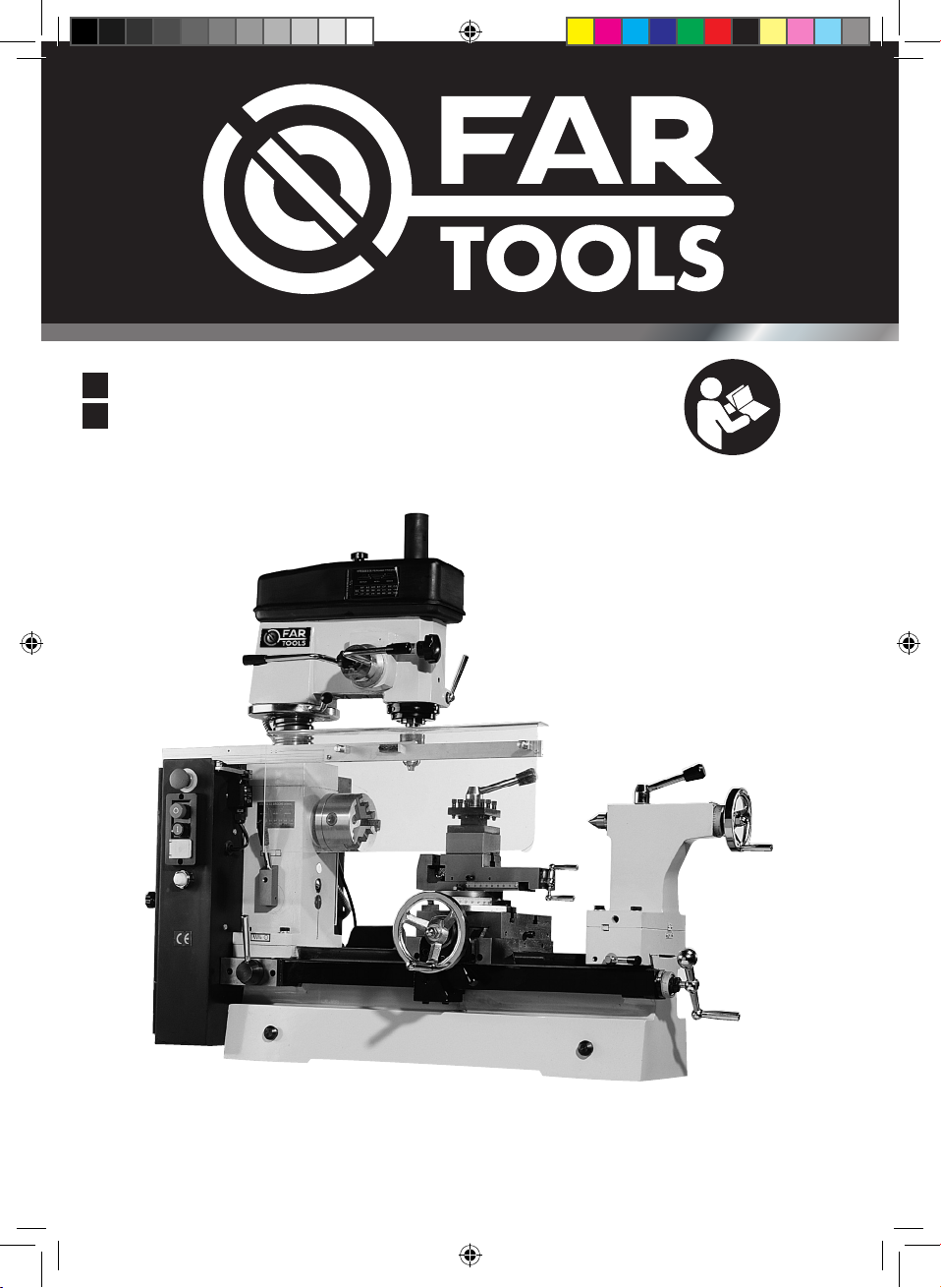
PREPARING THE INSTALLATION LOCATION
SLINGING DEGREASING
The bench where the unit is to be installed must measure at least: L 1000 mm, W 600 mm,
H 550 mm and must be able to bear 150 Kg. For safety reasons, the bench must be placed
against a wall while still leaving access to the rear of the machine. Four holes must be
drilled in the bench (see diagram).
Before slinging the machine,
take care to remove the wooden
spacers located on either side of
the base. See below for the most
suitable locations for placing the
sling under the machine
Degreasing is carried out using a
cloth dampened with white spi-
rit. Beware of the vapours that
can be toxic and be sure to pro-
perly ventilate the room
20 mm
690 (790) +/- 0,4 mm
750 (850) mm
210 mm
150 +/-0,2 mm
114135-Manual-D-EN.indd 3 21/03/12 10:44:13

©FAR GROUP EUROPE
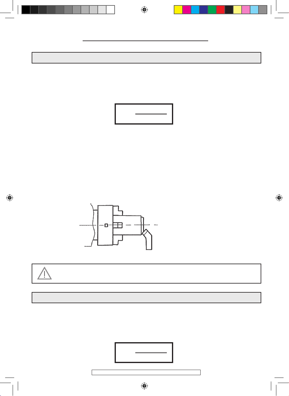
BALL VALVE OILER
with white spirit. Beware of the vapours that can be toxic and be sure to properly venti-
late the room. 13/ BALL VALVE OILER 14/ Using a stiff tip oil can, regularly oil those points
fitted with a ball valve oiler
LUBRICATING UNPROTECTED AREAS
Using an oiled brush, coat areas like the drive screw, the sliders, the cast iron bench...
BEFORE USE
Always let the lathe run under no load for 5 to 10 minutes so that the gearbox gears
can become lubricated
MAINTENANCE
During use, the lathe must receive regular maintenance to avoid impacting its produc-
tivity or its service life. After the first 20 days in service, drain the gearbox oil (using a
syringe not supplied). The oil is filled using the filter cap located on the top of the mo-
tor. The visual level indicator is located under the chuck (it must always be kept on the
halfway mark). Subsequently, oil changes should be made approximately every three
months (depending on frequency of use). Before starting a working session, lubricate
the machine in line with its lubrication requirements. WARNING: The oil level in the
chuck gear box must be checked regularly.
SPECIFIC SAFETY RULES
1- Always remove the chuck key from the chuck,
2- Never wear loose fitting clothing,
3- Always wear protective eye goggles,
4- Before replacing working tools or changing the speed or advance settings, always stop
the motor, disconnected the power connector and wait until the chuck has come to a
complete stop,
5- Attaching the part: Carefully attach the part before starting the lathe,
6- Stopping the lathe: Stop the lathe before taking any measurements on the part.
7- Braking: Braking the part or the chuck is dangerous
8- Eliminating chips: Never eliminate chips with your hands, always use a hook to do so.
114135-Manual-D-EN.indd 4 21/03/12 10:44:13

©FAR GROUP EUROPE
SLAVED SAFETY CASING
114135-Manual-D-EN.indd 5 21/03/12 10:44:23

©FAR GROUP EUROPE
QUICK SPINDLE LOWERING USING THE ARMS: DRILLING
SLOW SPINDLE LOWERING USING THE KNOB: GRINDING
BELT TENSION
114135-Manual-D-EN.indd 6 21/03/12 10:44:33

©FAR GROUP EUROPE
RAISING/LOWERING AND AIMING THE DRILLING HEAD
114135-Manual-D-EN.indd 7 21/03/12 10:44:39

©FAR GROUP EUROPE
MAIN CHARACTERISTICS
- Milling:
Max. machining diameter: 400 mm
Distance between tips: 400 mm
Max. longitudinal apron travel: 410 mm
Max. transverse carriage travel: 80 mm
Tool turret of size 20 x 20 max.
No. 3 jaw taper tailstock
Seven rotation speeds from 160 to 1360 rpm
Metric thread leadscrew (19 metric increments from 0.2 to 3 mm )
- Drilling/milling:
Max. drilling diameter: 16 mm
Max. milling diameter: 12 mm
No. 3 jaw taper mandrel
14 speeds (117 to 1300 rpm),
Working table: 150 x 200 mm
CAPACITY DIAGRAM
114135-Manual-D-EN.indd 8 21/03/12 10:44:46
©FAR GROUP EUROPE
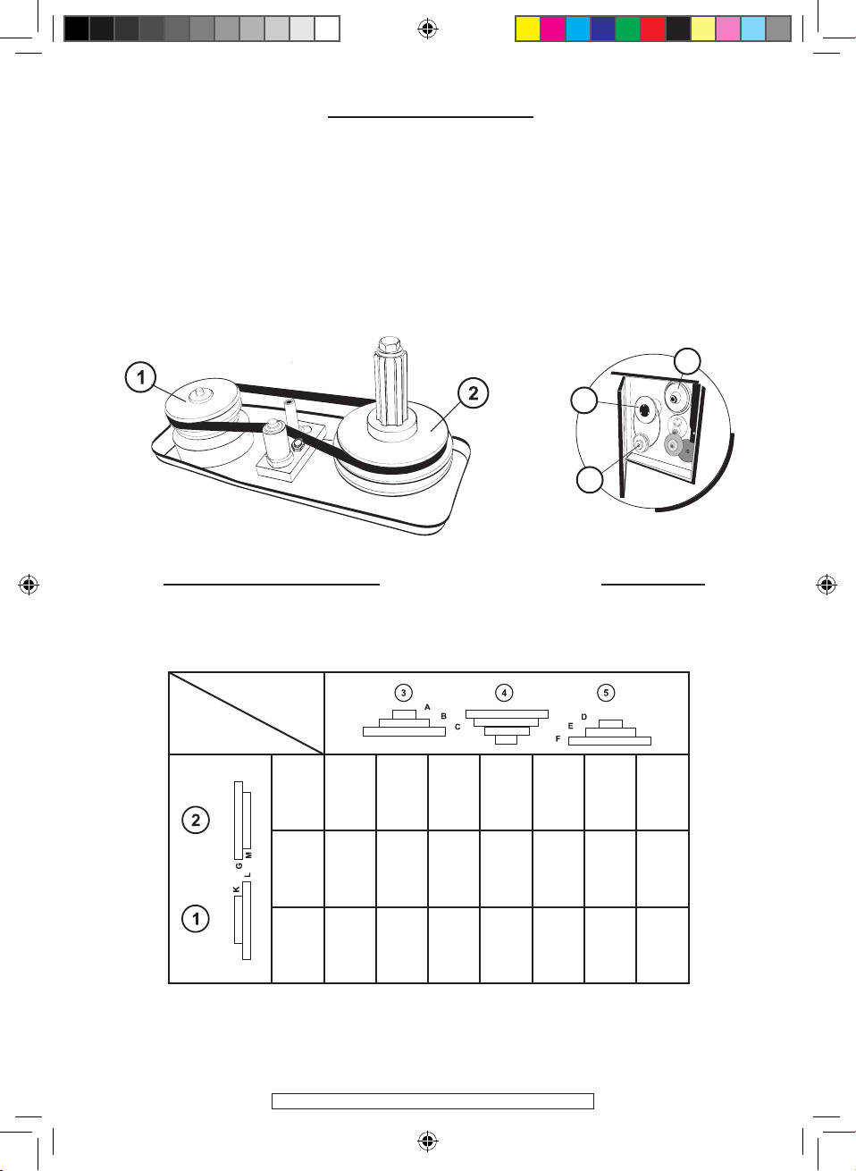
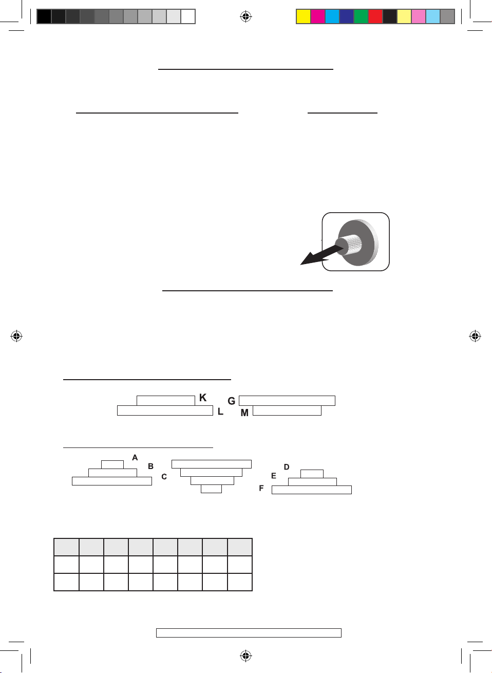
TRANSMISSION SYSTEM
Spindle speed settings: (in rpm)
The spindle speed is set to match the diameter of the part and the material to be ma-
chined, The setting is made after calculating the number of rpm and after determining
the position of the belts on the pulleys, referring back to the chart provided on the
machine.
DRILLING/MILLING UNIT LATHE UNIT
A-F A-E A-D B-F C-F B-E C-D
K-G 150 290 360 450 575 836 1300
L-M 117 220 276 345 440 640 1000
Drilling /
Milling
3= Motor pulley
4= Intermediate pulley
5= Spindle pulley
Lathe
Speed in rpm
3
5
4
114135-Manual-D-EN.indd 9 21/03/12 10:44:48
©FAR GROUP EUROPE
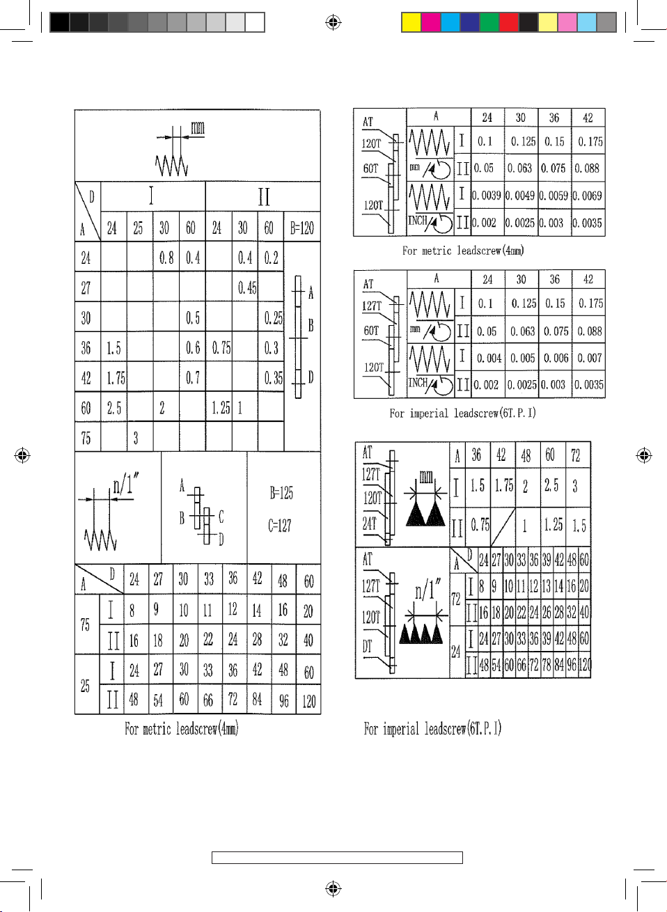
PROCEDURE FOR CHANGING GEARS TO ADJUST THE ADVANCE
The advance is set by changing the gears which are located in the cabinet on the left
hand side of the machine and by making reference to the table.
Gear A: 16 mm open end wrench
Gear B: 5 mm Allen wrench
Gear D: 16 mm open end wrench
Gear D adjustment screw: 5 mm Allen
wrench
Choose the advance or increment to be performed, refer back to the table below for the
choice of gears to use. I and II correspond to the No. 3 lever position.
Slacken and remove the nuts from gears A and D using a 16 mm wrench,
Slacken the 6 mm hollow head bolt on gear B using a 5 Allen wrench.
Slacken the 6 mm hollow head bolt used to adjust gear D using a 5 mm Allen wrench.
Remove gears A and D (taking care to not lose the key!),
Take the gears that match the advance or increment to be performed.
Reassembly: Refit gear A and tighten down the 16 mm nut, Adjust gear B in relation to
gear A and tighten down the 6 mm Allen head bolt, Lastly, refit gear D onto gear B by
sliding the support and locking down the 6 mm Allen head bolt
WARNING: Before performing any gear replacement operation, ensure that the power
cable is disconnected.
Transmission box
Unit: mm
I II
24 25 30 60 24 30 60
24 0,8 0,4 0,4 0,2
27 0,45
30 0,5 0,25
36 1,5 0,6 0,75 0,3
42 1,75 0,7 0,35
60 2,5 2 1,25 1
75 3
AD
114135-Manual-D-EN.indd 10 21/03/12 10:44:52
©FAR GROUP EUROPE
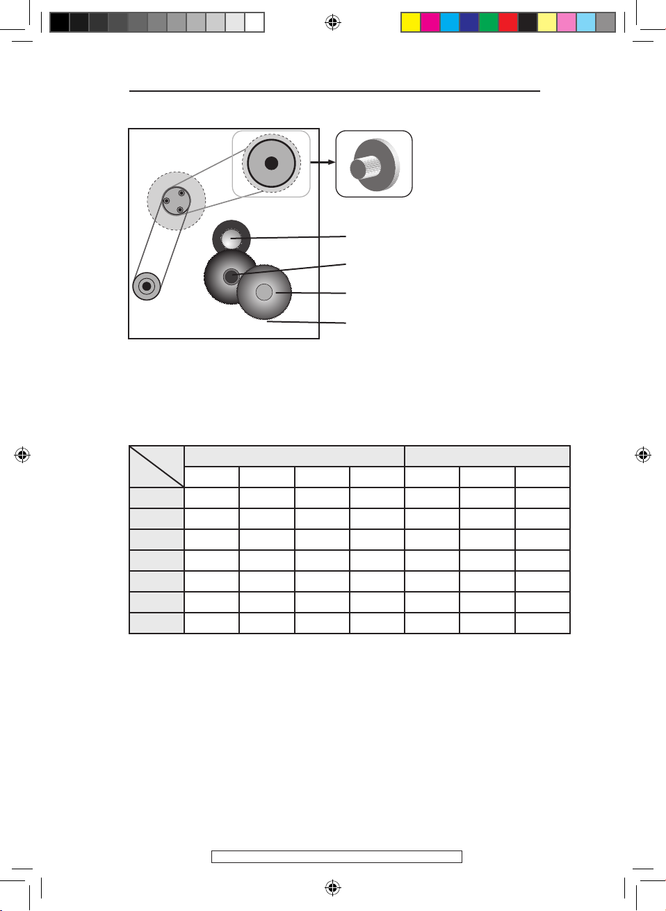
MOVING AND ADJUSTING THE TAILSTOCK CENTRE
114135-Manual-D-EN.indd 11 21/03/12 10:44:53
©FAR GROUP EUROPE
USING THE MILLING DRILLING HEAD
SETTING MILLING SPINDLE SPEEDS
DRILLING-MILLING HEAD PULLEYS
PULLEYS IN THE REAR CASING
When using the drilling/milling head and for improved ease of working, it is preferable
to remove the mandrel from the lathe.
There are 14 speed adjustment possibilities ranging from 117 to 1300 rpm. The spindle
speed is set depending on the diameter of the cutter or drill used and the material to
be machined or drilled. This is set after calculating the rpm and the position of the belts
on the pulleys..
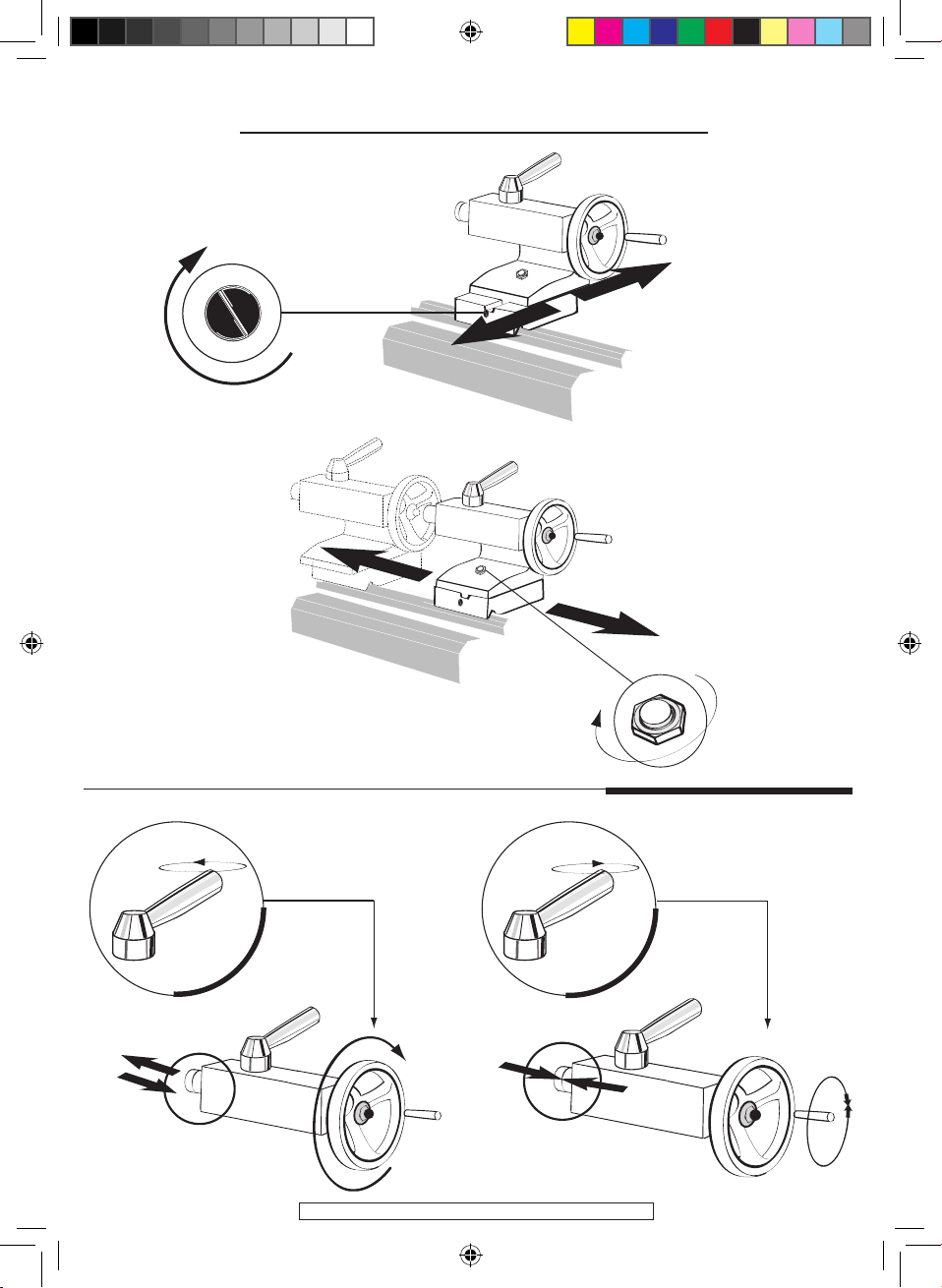
RAISING / LOWERING THE HEAD HEAD CLUTCH
Slacken the 6 mm hollow head
bolt using an 8 mm Allen wrench.
Turn the chromed ring using the
levers
- Clockwise to lower,
- Counter clockwise to raise, As
the head position is set, align
the drilling chuck axis with the
lathe spindle axis (to better use
the drilling head), Lock the head
using the hex head bolt.
To engage the drilling/milling
head:
Open the transmission system
door then push the knobbed
ring all the way in, which auto-
matically releases the lathe spin-
dle and engages the milling head
spindle
To change the drilling head belt posi-
tion:
Remove the casing,
Slacken the belt tensioner,
Change the position of the belts then
retighten the tensioner while applying
pressure to the belt.
Refit the casing.
A-F A-E A-D B-F C-F B-E C-D
K-G 150 290 360 450 575 836 1300
L-M 117 220 276 345 440 640 1000
Speed in rpm
Spindle pulleys
MOTOR PULLEYS INTERMEDIATE PULLEYS SPINDLE PULLEYS
114135-Manual-D-EN.indd 12 21/03/12 10:44:54
©FAR GROUP EUROPE
114135-Manual-D-EN.indd 13 21/03/12 10:44:55
©FAR GROUP EUROPE
Matière / Material
Outil coupant / Cutting tool
Acier rapide /
Steel
Carbure / Carbide
Acier / Steel
Doux /Soft 30-40 daN/mm230-40 m.min-1 140-300 m.min-1
40-50 daN/mm228-34 m.min-1 130-280 m.min-1
Demi dur /
Half hard
50-60 daN/mm223-30 m.min-1 100-240 m.min-1
60-70 daN/mm220-25 m.min-1 85-200 m.min-1
Dur / Hard 70-80 daN/mm217-22 m.min-1 70-160 m.min-1
80 daN/mm2-> 12-15 m.min-1 60-120 m.min-1
Laiton / Brass 40-65 m.min-1 300-600 m.min-1
Bronze 26-33 m.min-1 270-500 m.min-1
Bronze phosphoreux / phosphorous 18-24 m.min-1 250-400 m.min-1
Aluminium / Aluminum 120-165 m.min-1 800-1300 m.min-1
Cuivre / Copper 90-125 m.min-1 600-900 m.min-1
Fonte / Cast iron 15-25 m.min-1 30-100 m.min-1
N = 1000 x V
π x D
N : Vitesse de rotation ( tr.min-1 ) / Rotation speed ( rpm ).
V : Vitesse de coupe ( m.min-1 ) / Cutting speed ( m.min-1 ).
D : Diametre de la pièce ( mm ) / Workpiece diameter ( mm ).
Expl : Alu ø 40 mm.
N = 1000 x 120
π x 40
N = 955
40 mm
SPEED CHOOSING
Le choix de la profondeur de passe et de la vitesse d’avance doit être basée sur la matière
de la pièce, le type de l’outil et le niveau de l’opérateur.
The choice of cutting depth and feeding speed should be based on the workpiece, the
tool and the operator’s skill level. (114070 / Choosing drive speeds / Gear combinations
for straight turning / thread cutting)
En alésage, la vitesse doit être diminuée de 10 à 20 %
During boring, the speed must be lowered from 10 to 20%
114135-Manual-D-EN.indd 14 21/03/12 10:44:55
©FAR GROUP EUROPE
SHARPENING TOOLS
Note: The grinding head is the ideal tool for this operation. The grinding head may be
fitted with a green grinder (green silicon carbide) specially designed to sharpen carbide
tools
Never heat the carbide and cool it regularly in water
Always pass the carbide plate support part over a fettling grinder.
Metal carbides
WARNING: Always wear protective goggles while sharpening
(Cobalt, tungsten, titanium, boron combinations) These carbides that are obtained with
a special heat treatment called sintering, are used in the form of disks or “inserts”. The
latter are placed onto the tool body and attached by brazing using a special brazing
powder
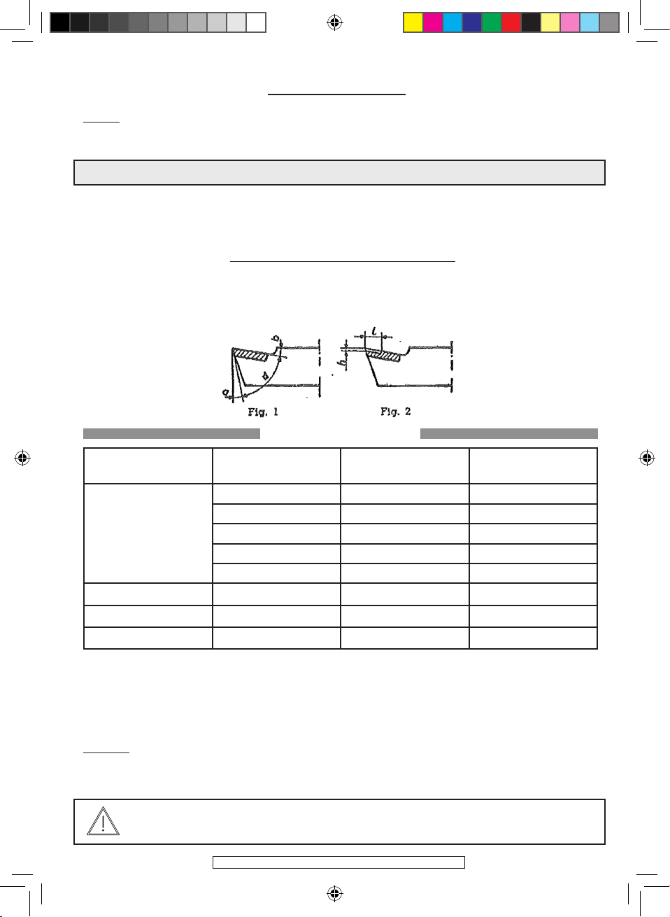
LATHE TOOLS with metal carbide tabs
a, delivery angle.
. Characteristic angles: b, sharpening slope
(a+b+d=90°) d, cutting angle.
Angle values a and b
Metals and alloys to
be machined
/ Resistance R
kg/mm2
Delivery
angle a
Sharpening slope
t
Steel
up to 50 kg 6° 22 to 25°
50 to 60 kg 6° 18 to 20°
60 to 70 kg 6° 15 to 18°
70 to 80 kg 5° 12 to 15°
80 to 95 kg 5° 10 to 12°
Grey cast iron 6° 8 to 10°
Various bronzes 7° 5 to 6°
Aluminium 8° 25 to 30°
Chip breaker (Fig.2): When machining steel grades only, the tool cutting edge receives suitable
sharpening. The length l of the chip breaker varies according to the grade of steel and the pass
load:
For steel up to 50 kg/mm2.............. l= 3.5 mm
For steel of 55 to 75 kg/mm2.............. l= 3.0 mm
For steel of 80 to 95 kg/mm2.............. l= 2.5 mm
Remark. The depth or the height of the chip breaker does not vary, it is 0.5 mm (approximately).
114135-Manual-D-EN.indd 15 21/03/12 10:44:56
©FAR GROUP EUROPE
VARIOUS GRINDING/MILLING OPERATIONS
a/ Comprises removing metal from the part surface,
b/ Clamp the part into the chuck, always use the same jaw tightening square. Never let
the part protrude by more than twice its diameter (spinning in the air),
c/ Position the tool tip so that it is perfectly aligned with the part axis (to do this, use steel
shims that are placed under the tool body)
d/ Start the machine after first setting the speed in rpm.
e/ Angle the tool to the part face, push the tool back, set a cutting depth of 0.5 to 1 mm
max. by turning wheel 17 on the longitudinal carriage, then advance towards the centre
of the part by turning wheel 18 on the transverse carriage at a consistent rate.
f/ Never remove the part if it is to be corrected
g/ Where possible, lubricate using a can containing soluble oil and water and a brush.
a/ This comprises removing material over the diameter of the part,
b/ Use a cutting tool, position the tool tip perfectly in line with the part axis,
c/ Start the machine to allow automatic advance after first setting the speed in rpm
FACING
STRAIGHT TURNING
N = 1000 x V
π x D
N = 1000 x V
π x D
WARNING: Always wear protective goggles and remove the chips using a
hook, never with your hands
A right hand 45° facing tool
114135-Manual-D-EN.indd 16 21/03/12 10:44:56

©FAR GROUP EUROPE
Example:
To advance by 0.2 mm per revolution: Gear A=24, B=120, D=60, lever No. 3 on position II,
d/ Set the tool at a tangent to the part diameter. Reverse the tool to the right to escape
from the part. Set a penetration depth of 0.5 mm.
10 divisions on the Vernier callipers = 1 mm in diameter.
Start the AUTO advance function using lever No. 3 .
e/ Release at the desired moment (desired length). Be careful to allow for inertia.
f/ Reverse the tool away to the right,
g/ Stop the machine and take measurements
This operation is required before boring. It uses a drill bit. There are two kinds of drill
bits as described below. Refer to the table for more detailed explanations
Cylindrical or conical:
Cylindrical: For bits with a diameter of 0.5 to 13 mm that fit into a self tightening chuck
(option 111482).
Conical: For larger diameter bits that fit directly into the cone on the sliding headstock,
a/ Position the conical drill bit into the cone on the sliding headstock, first making sure
that the bit is properly sharpened,
b/ Start the machine after first setting the rpm,
c/ Move the tailstock centre up to the part, and lock (lever 16),
d/ Then move the bit by turning the handle smoothly.
WARNING: Avoid hitting the tool in the jaws. If the part is too long, then
you will need to fit the centred tailstock fitted with a spinning tip. Always
wear protective goggles.
Always remove the chips using a hook, never with your hands
WARNING: We recommend lubricating the part using a can containing so-
luble oil and water and a brush. For very long drilling lengths, we recom-
mend removing flashing from time to time. Before starting any drilling,
mark the centre point using a centring drill mounted in the self tightening
chuck
DRILLING
Cutter tool
114135-Manual-D-EN.indd 17 21/03/12 10:44:57

©FAR GROUP EUROPE
BORING
a/ Comprising removing matter from a hole to enlarge it so as to achieve a good surface
condition,
b/ Use a boring tool with a 45° angle to bore a through hole or make a chamfer or use a
boring-dressing tool when boring a non-though hole, bring the tool to the same height
(again using shims) as the part axis or slightly higher,
c/ Start the machine in automatic advance mode, after first setting the rpm and the
advance
Example:
Advance by 0.25 mm per revolution: Gear A=30, B=120, D=60, Lever 3 on position II,
d/ Set the tool at a tangent to the part face by turning wheel 17. Make a mark on the
Vernier callipers, then bring to a tangent inside the hole in the part by turning wheel 14.
PAY ATTENTION to the anti-clockwise direction, make a mark on the Vernier callipers.
e/ Disengage the tool from the part using wheel 17. Take a cutting depth of 1 mm per
pass off the diameter (10 divisions of the Vernier calliper for wheel 14), then regularly
advance using wheel 17 or in automatic mode by actuating lever 2. When the bore is a
through one (to bore a 10 mm depth), then have the wheel 17 Vernier callipers perform
ten turns from the point where you made a mark.
f/ Disengage the tool then take a measuremen
N = 1000 x V
π x D
WARNING: Always wear protective goggles and remove the chips using a
hook, never with your hand
Rotation speeds & advances
Helicoidal drills
angles of the edges
Steel Steel Steel
Cast iron
Metal to work
Normal cut Normal cut
Insufficient cut
Excessive cut
Boring tool angled 45 ° Boring tool - dressing tool
RPM
Advance
mm/r
Drill diameter
Advance
mm/r
Advance
mm/r
Advance
mm/r
RPM
RPM
RPM
114135-Manual-D-EN.indd 18 21/03/12 10:44:58

©FAR GROUP EUROPE
CUTTING
OUTER AND INNER THREAD CUTTING
a/ Comprises cutting a part that has already been drilled and
bored to obtain a spacer or washer,
b/ Use a cutting tool. Bring the tool tip to the same height as
the axis (again using shims) or a little below the part centre,
c/ Start the machine after first setting the rpm,
d/ Offset your tool to the left (wheel 17) using a straight edge to check the distance
between the part face and the right hand side of your tool. Stop as soon as you obtain
the desired distance and add 1 mm to it to correct the face surface.
e/ Manually and regularly advance the tool using wheel 14. We recommend lubricating
(with soluble oil and water) using a brush. As soon as the tool drills through into the
bore, reverse and disengage to the right
Designation: Threads are designated by the M symbol, followed by their diameter and
pitch in mm, separated by a multiplication sign. Example: M 30 x 3.5, i.e. M 30 for a 30
diameter thread with a 3.5 mm thread pitch. Standard threads are:
/ Outer thread: The tool profile sharpening angle for cutting a metric thread is 60°, The
tool profile sharpening angle for cutting a Whitworth thread (English pitch) is 55°,
CUTTING A TRIANGULAR THREAD
Tool penetration
- Normal penetration (see Fig. below).
The tools are aimed and their profiles sharpened to 60°
or 55° using angle centre gages.
Tool height position. Absolutely aligned with the tip
axes (part axis).
nominal Diameter M Typical pitch P (mm)
M 3 0,6
M 4 0,7
M 5 0,8
M 6 1
M 8 1,25
M 10 1,50
M 12 1,75
M 14 2
M 16 2
M 18 2,5
M 20 2,5
M 22 2,5
M 24 3
M 27 3
M 30 3,5
N = 1000 x V
π x D
Outer
threading
tool
Outer threa-
ding tool
Cutting tool
114135-Manual-D-EN.indd 19 21/03/12 10:44:59

©FAR GROUP EUROPE
The tool is aligned with the part using a centre gage. This centre gage is useful when
checking tool sharpening.
1/ Once the tool is correctly sharpened and aligned, set the rpm, a setting that will be far
slower than the theoretical rpm rate, (approx. 50% less).
Example: For an M 20 x 2.5, semi-hard steel=30
setting that will be far slower than the theoretical rpm rate, (approx. 50% less).
Example: For an M 20 x 2.5, semi-hard steel=30 132/ To cut a thread, a speed of 220 rpm
will be used
2/ Then the pitch will be set by changing the gears. For a 2.5 mm pitch, the choice will be
A=60 teeth, B=120 teeth and D=24 teeth and lever 3 will be set to I,
3/ Before starting machining, calculate the tool penetration depth using the following
formula:
Example:
For a 2.5 mm pitch: 0.61 x 2.5 = 1.525 mm in radius
4/ Pull the part far enough out of the chuck when cutting a thread so that no collision
occurs between the thread cutting tools and the chuck jaws (as the chuck does not have
a brake). The technique used to stop thread cutting is first of all to shutdown the motor
and then to quickly withdraw the tool.
5/ Start up. Place the tool at a tangent to the part. The part has a nominal diameter of
20. For an M 20 x 2.5 mm thread, make a pencil mark on the Vernier callipers. Disengage
the tool to the right on removing it from the part.
Take a 0.5 mm cutting depth (for the first pass only), i.e. 10 divisions on the Vernier cal-
lipers. Stop the machine.
Engage lever 2 (leadscrew clutch),
Lubricate the part with cutting oil.
Start up and place one hand on wheel 14 to disengage the tool when it reaches the de-
sired thread length, then place the other hand on the motor stop button.
Reverse the machine to return the tool to its starting position, and start another 0.25
pass (5 divisions on the Vernier calliper in addition to the 10 divisions already taken du-
ring the first pass)
- Repeat the operation six times to achieve the theoretical 1.525 cutting depth.
- After the final pass, perform one more blank pass to correct tool part flex,
- Back off the tailstock centre and try the thread with a 20 mm 2.5 pitch nut.
Pdp = 0,61 x P
N = 1000 x 30 = 477 tr/ min
π x 20
WARNING: Do not disengage lever 2 for the tool may no longer fit into
the same pitch during the next pass.
114135-Manual-D-EN.indd 20 21/03/12 10:44:59
Table of contents
Other Far Tools Lathe manuals


Popular Lathe manuals by other brands


Grizzly
Grizzly G1495 parts list

Jet
Jet E-1440VS Operating instructions and parts manual

Gude
Gude GDM 1000 Translation of original operating instructions

Central Machinery
Central Machinery 65044 Set up and operating instructions

Delta
Delta 46-756 instruction manual

Southbend
Southbend SB1015F insert Manual insert


