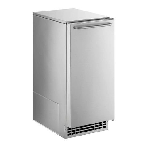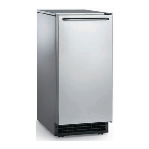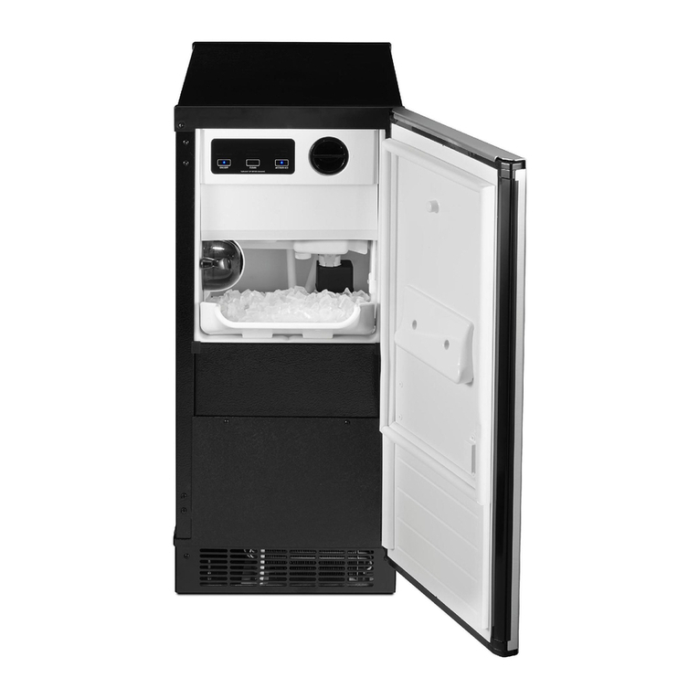
FOR THE INSTALLER: Stacking
KSNM30 STACKING KIT INSTRUCTIONS
The purpose of the this kit is to connect the ice
level controls from the bottom machine to an
additional circuit board so that they control
both machines.
/////////////////////////////////////WARNING//////////////////////
/////////
Disconnect electrical power to both
machines while installing this kit.
////////////////////////////////////////////////////////////////////////////
//////////
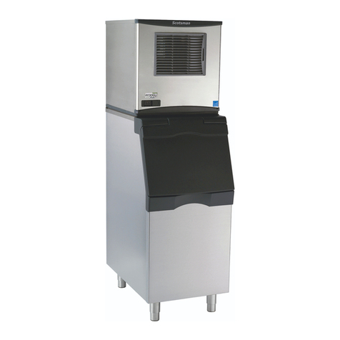
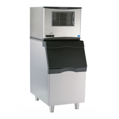
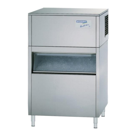
1. Stack the two unit’s by removing the top
panel from the lower unit (assumed to be
already installed on the bin) and, using a
mechanical lift, place the upper unit onto the
lower one. Secure the two units together with
the hardware (straps and bolts) provided with
the upper unit.
2. Remove the front panels from both units.
3. Remove the lower unit’s existing ice chute
cover, and replace it with the one from the kit.
Transfer the spout switch assembly to the new
cover:
A. Remove microswitch.
B. Pull o-ring out from between chute cover
and spout switch assembly, push spout switch
assembly through chute cover. Reverse to
reassemble on the new cover.
4. From below the upper unit base, insert the
ice chute extension (from the kit) through the
upper unit ice chute port, and onto the upper
unit’s ice chute.
5. Pull the chute extension down and slide it
into the lower unit’s new ice chute cover.
6. Remove the control box covers from both
units.
LOWER UNIT:
7. Remove the two lower control box mounting
screws and use them to mount the stacking kit
circuit board (upper flange only) in between
the control box and the bulkhead panel.
8. Remove the bushing that the ice level
sensor wires pass through from the control
box.
9. Unplug the "photo trans" ice level sensor
from the connection on the ice machine circuit
board, pull it out of the control box, and plug it
into the "photo stack" plug on the stacking kit
circuit board.
10. Unplug the "LED" ice level sensor from the
ice machine circuit board, pull it out of the
control box, and plug it into the "LED Stack"
connection on the stacking kit circuit board.
11. One by one, pass all of the wires from the
stacking kit circuit board through the hole in
the control box, and reinstall the bushing
removed in step 8, then:
A. Plug the two pin plug onto the ice machine
circuit board socket marked "LED" (CX2).
B. Plug the 3 pin plug onto the ice machine
circuit board socket marked "Photo Trans"
(CX4).
12. Unplug the wire harness connecting the
transformer to the ice machine circuit board,
and remove from the machine, then:
A. Plug the 4 pin plug into the ice machine
circuit board socket marked "power" (CX1).
B. Connect the two free wires from the 4 pin
plug (connected above) to the transformer
(marked "load").
13. Plug the last wire from the stacking kit
circuit board into the "Remote Lamp" (located
in the upper left corner of the board) plug on
the ice machine circuit board.
UPPER UNIT:
14. Unplug, but leave in the control box the
"photo trans" and "LED" ice level sensor
wires. Leave in place on ice chute.
15. There are two different wires in the kit
separate from the circuit board; one has a
three pin connector and the other has a two
pin connector. Find the one with the three
pins, and insert the big end onto "photo trans"
on the ice machine circuit board. Pass the
other (smaller) end of the wire through the
bushing in the control box, and through the
bushing beside the ice chute in the base of
the upper unit.
16. Find the wire with the two pin connector,
and insert the bigger two pin plug onto "LED"
FM1500R
November, 1988
Page 8
