7
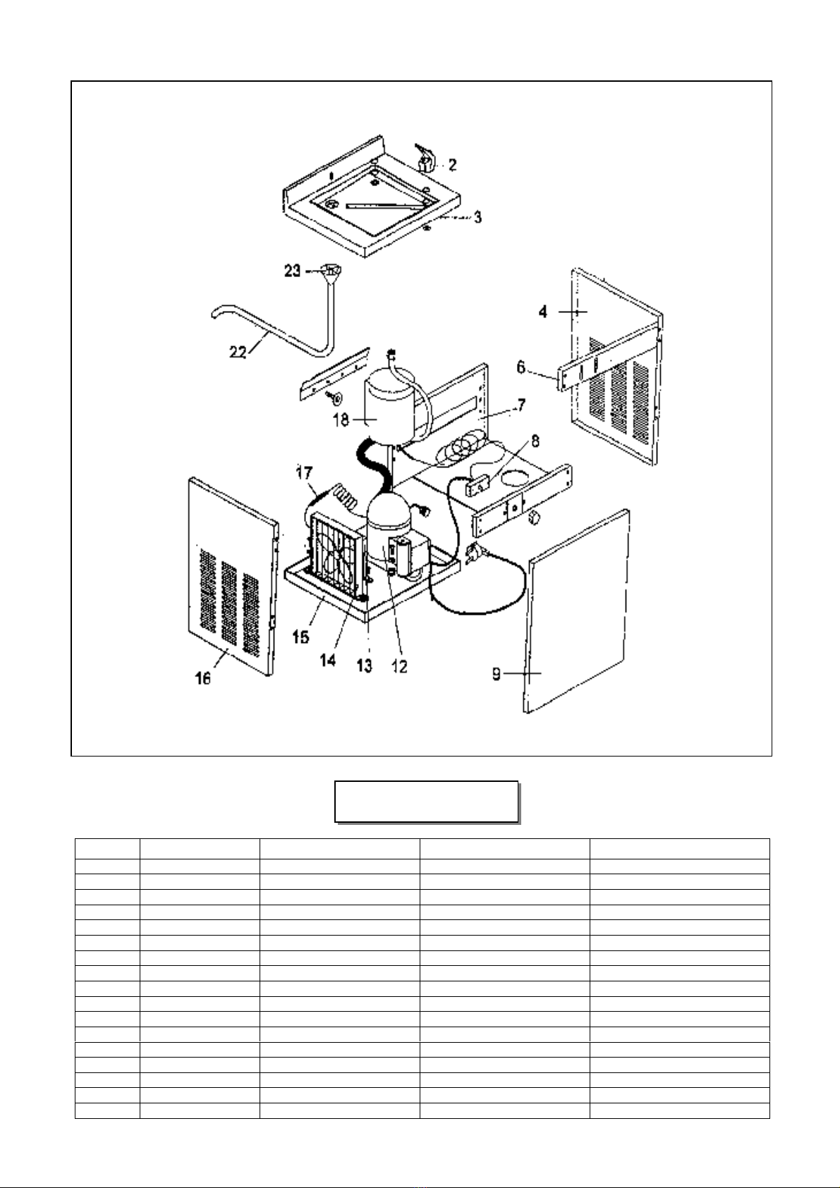
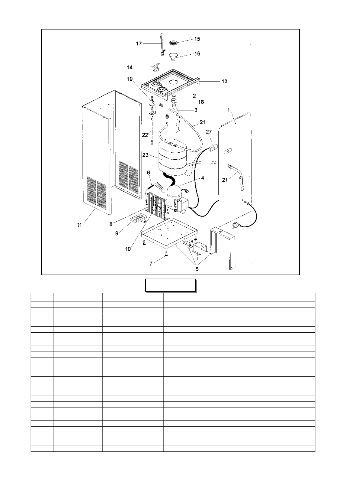
ITEM PART NUMBER DESCRIPTION DESIGNATION DESCRIZIONE
1 CS 00001702728 REAR PANEL PANNEAU ARRIERE PANNELLO POSTERIORE
2 CS 00002661525 GASKET GARNITURE GUARNIZIONE
3 CS 00002801334 DRAIN TUBE TUYAU TUBO SCARICO
4 CS 00001581174 COMPRESSOR 230/50-60/1 COMPRESSEUR 230/50-60/1 COMPRESSORE 230/50-60/1
5 CS 00001702724 UNIT BASE ENS. CHÂSSIS BASAMENTO
6 CS 00002641411 DRIER DESHYDRATEUR FILTRO DEUMIDIFICATORE
7 CS 00002781315 LEG PIED PIEDINIO
8 CS 00001601109 CONDENSER CONDENSEUR CONDENSATORE
9 CS 00002781187 FOOT PEDAL PEDALE PEDALE
10 620419 00 FAN MOTOR 230/50-60/1 MOTEUR VENTILATEUR MOTOVENTILATORE 230/50-60/1
11 CS 00001702727 FRONT/SIDES PANEL PANNEAU AVANT/LATERAL PANNELLO FRONTALE/LATERALE
13 CS 00002781142 SINK CUVETTE LAVELLO
14 CS 00002521707 PROJECTOR PROJECTEUR RUBINETTO A ZAMPILLO
15 CS 00002641419 FILTER FILTRE FILTRO
16 CS 00002781143 DRAIN FUNNEL ENTONNOIR PILETTA SCARICO
17 CS 00002521705 GLASS FILLER COL DE CIGNE RUBINETTO A COLLO DI CIGNO
18 CS 00002521320 DRAIN FITTING RACCORD EVACUATION RACCORDO DI SCARICO
19 CS 00815613112 WATER REG. VALVE ENS. REGULATEUR EAU VALVOLA REG. ACQUA
21 CS 00002801349 TUBE PE (1 METER) TUYAU (1 METRE) TUBO PE (1 METRO)
22 CS 00002781191 FOOT PEDAL CABLE CÂBLE DE PEDALE CAVO PEDALE
23 CS 00811003011 EVAPORATOR EVAPORATEUR EVAPORATORE
CS 00005681902 INSULATION ISOLATION ISOLAMENTO
27 CS 00003824910 THERMOSTAT THERMOSTAT TERMOSTATO
SCW 14 B