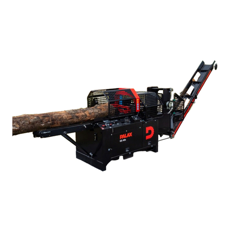
Palax COMBI M User manual

INSTRUCTION MANUAL
PALAX COMBI M
Powered by tractor
Powered by electric motor
Featuring conveyor

Ohjekirja Palax combi M 2004.1 En
2

Ohjekirja Palax combi M 2004.1 En
3
1 FOREWORD........................................................................................................................................................... 7
1.1 EU DECLARATION OF CONFORMITY ..................................................................................................................... 7
1.2 INTENDED USE OF THE MACHINE ........................................................................................................................... 8
Maximum size of the wood:....................................................................................................................................... 8
1.3 MARKINGS AFFIXED TO THE MACHINE .................................................................................................................. 8
1.4 NAMEPLATES ........................................................................................................................................................ 8
Nameplate on the machine ........................................................................................................................................ 8
Nameplates on the electric drive............................................................................................................................... 8
1.5 SAFETY INSTRUCTIONS.......................................................................................................................................... 9
1.6 NOISE EMISSION AND VIBRATION .......................................................................................................................... 9
1.7 RESPONSIBILITIES OF THE OPERATOR .................................................................................................................... 9
1.8 OPERATING CONDITIONS ..................................................................................................................................... 10
1.9 MACHINE CONFIGURATIONS................................................................................................................................10
1.10 TERMS OF WARRANTY .................................................................................................................................... 10
The warranty covers................................................................................................................................................ 10
The warranty does not cover................................................................................................................................... 11
1.11 OPERATING INSTRUCTIONS FOR THE COMBUSTION ENGINE ............................................................................ 11
2 TAKING DELIVERY AND PRE-ASSEMBLY OF THE MACHINE ............................................................ 11
2.1 THE TRANSPORT SET-UP AND UNPACKING ........................................................................................................... 11
2.2 ACCEPTANCE INSPECTION ................................................................................................................................... 11
2.3 MAIN PARTS OF THE MACHINE ............................................................................................................................ 12
2.4 ASSEMBLY OF THE TABLE EXTENSION, FIGURE 2 ................................................................................................ 12
2.5 ASSEMBLY OF THE CONVEYOR SUPPORT, FIGURE 2............................................................................................. 12
2.6 PROTECTIVE COVER OF CROSS-CUT SAW-BLADE, FIGURE 3................................................................................. 13
2.7 PROTECTIVE NET OF CROSS-CUT SAW-BLADE, FIGURE 3 ..................................................................................... 13
2.8 PROTECTIVE COVER OF SPLITTING TROUGH, FIGURE 4 ........................................................................................ 13
2.9 ASSEMBLY OF THE LOG-STOP, FIGURE 5 ............................................................................................................. 13
2.10 SETTING THE LOG-STOP .................................................................................................................................. 13
2.11 TOPPING UP HYDRAULIC OIL........................................................................................................................... 13
2.12 ASSEMBLY OF THE CONVEYOR, FIGURE 6....................................................................................................... 14
2.13 INSTALLING THE V-BELT, FIGURE 6 ............................................................................................................... 14
2.14 INSTALLING THE ATTACHMENT PLATE AND THE SUPPORT WIRES, FIGURE 8................................................... 14
2.15 INSTALLING THE CONVEYOR WINCH, FIGURE 9 .............................................................................................. 14
2.16 INSTALLING THE WINCH WIRE ........................................................................................................................ 15
2.17 BRINGING THE CONVEYOR INTO THE TRANSPORT POSITION............................................................................ 15
2.18 BRINGING THE CONVEYOR INTO THE WORK POSITION .................................................................................... 15
2.19 FIXING THE LIFTING HANDLE, FIGURE 10 ....................................................................................................... 15
2.20 LOCKING THE DEBRIS TRAY, FIGURE 10 ......................................................................................................... 15
2.21 LIFTING AND TRANSFERRING THE MACHINE, FIGURE 11 ................................................................................ 15
3 OPERATION OF THE FIREWOOD PROCESSOR POWERED BY DIFFERENT POWER SOURCES 16
3.1 POWERED BY A TRACTOR .................................................................................................................................... 16
3.2 EMERGENCY STOP SWITCH OF THE TRACTOR POWERED MACHINE, FIGURE 12 .................................................... 16
Operation of the clutch, Figure 12.......................................................................................................................... 16
Adjusting the clutch, Figure 13 ............................................................................................................................... 16
Required measures in an emergency situation........................................................................................................ 17
3.3 ELECTRIC DRIVE, START AND EMERGENCY STOP................................................................................................. 17
Starting.................................................................................................................................................................... 17
Emergency stop of a machine powered by electric motor, Figure 14 ..................................................................... 17
Starting the electric motor at sub-zero temperature, Figure 12.............................................................................. 17
Selecting the power source, electricity or tractor, Figure 15 and 16...................................................................... 18
3.4 HONDA PETROL ENGINE, START, STOP AND EMERGENCY STOP............................................................................ 18
Starting the engine .................................................................................................................................................. 18
Stopping .................................................................................................................................................................. 18
Emergency stop ....................................................................................................................................................... 18
3.5 LOMBARDINI DIESEL ENGINE, START, STOP AND EMERGENCY STOP.................................................................... 18
Stopping .................................................................................................................................................................. 18
Emergency stop ....................................................................................................................................................... 18
4 USE OF THE FIREWOOD PROCESSOR, CROSS-CUT OPERATION ...................................................... 19
4.1 PREPARATIONS BEFORE THE USE OF THE MACHINE, ALL MODELS........................................................................ 19
4.2 OPERATING THE CROSS-CUT SAW, BEFORE THE OPERATION ................................................................................ 19

Ohjekirja Palax combi M 2004.1 En
4
4.3 DURING THE OPERATION ..................................................................................................................................... 19
4.4 PLACING THE WOOD ON THE DECK ...................................................................................................................... 19
Right, the log is supported by the rollers, Figure 18............................................................................................... 20
4.5 CROSS-CUT OPERATION....................................................................................................................................... 20
4.6 DISTURBANCES DURING CROSS-CUT OPERATION AND THEIR REMEDY................................................................. 20
Crooked trees .......................................................................................................................................................... 20
Big trees .................................................................................................................................................................. 20
4.7 CUTTING THE SMALL TREES ................................................................................................................................20
5 USE OF THE FIREWOOD PROCESSOR, SPLITTING OPERATION........................................................ 20
5.1 SPLITTING CYLINDER .......................................................................................................................................... 20
5.2 MANUALLY-OPERATED HIGH-SPEED VALVE, FIGURE 20 ..................................................................................... 20
5.3 AUTOMATIC HIGH-SPEED VALVE ......................................................................................................................... 21
5.4 SPLITTING WEDGES ............................................................................................................................................. 21
Short, straight wedge, optional ............................................................................................................................... 21
In 2/4 ways, standard .............................................................................................................................................. 21
In 2/6 ways, option .................................................................................................................................................. 21
5.5 MANUAL ADJUSTMENT OF THE SPLITTING BLADE, FIGURE 21............................................................................. 21
5.6 HYDRAULIC HEIGHT ADJUSTMENT OF THE SPLITTING BLADE, OPTIONAL ............................................................ 21
5.7 ADJUSTING THE SPEED OF THE SPLITTING BLADE ADJUSTMENT CYLINDER, FIGURE 23 ....................................... 22
Adjustment............................................................................................................................................................... 22
5.8 DISTURBANCES DURING THE SPLITTING OPERATION AND THEIR REMEDY ........................................................... 22
Stuck wood .............................................................................................................................................................. 22
5.9 RE-SPLITTING THE LOGS SAFELY ......................................................................................................................... 22
5.10 HOW THE SAFETY FEATURES AFFECT THE OPERATION OF THE MACHINE ........................................................ 22
Foot pedal, Figure 24 ............................................................................................................................................. 22
Protective cover of splitting trough, Figure 25 ....................................................................................................... 23
6 OPERATION OF THE SPLITTING DEVICE.................................................................................................. 23
6.1 SENSOR, FIGURE 26 ............................................................................................................................................ 23
6.2 PARTS OF THE SPLITTING DEVICE, FIGURE 27...................................................................................................... 23
6.3 OPERATIONAL PRINCIPLE OF LAUNCHING............................................................................................................ 23
6.4 HAND-START OF THE SPLITTING MOTION, FIGURE 28.......................................................................................... 23
CONTROLS OF THE HYDRAULIC VALVE ......................................................................................................................... 24
Tightener, part 1 ..................................................................................................................................................... 24
Locking lever, part 2 ............................................................................................................................................... 24
Launching rod, part 3 ............................................................................................................................................. 24
Control lever, part 4................................................................................................................................................ 24
Hydraulic valve, part 5 ........................................................................................................................................... 24
Launching spring, part 6......................................................................................................................................... 24
Launching lever, part 7........................................................................................................................................... 24
Adjustment mark, 8 ................................................................................................................................................. 24
7 MAINTENANCE OF THE MACHINE.............................................................................................................. 24
7.1 CROSS-CUT SAW-BLADE...................................................................................................................................... 24
Removing the cross-cut saw-blade, Figure 30 ........................................................................................................ 24
Sharpening the blade, hard-metal blade ................................................................................................................. 24
Pre-stressing the saw-blade, hard-metal blade....................................................................................................... 25
7.2 GUIDE OF CROSS-CUT SAW-BLADE, FIGURE 31 ................................................................................................... 25
Adjustment of the saw-blade guide.......................................................................................................................... 25
7.3 V-BELTS OF THE ANGULAR GEAR, FIGURE 32...................................................................................................... 25
Tightening the belts................................................................................................................................................. 25
Replacement of the V-belts, angle gear, Figure 33................................................................................................. 26
7.4 CHANGING THE OIL IN THE ANGULAR GEAR ........................................................................................................ 26
7.5 LUBRICATING THE MACHINE, FIG 34................................................................................................................... 26
7.6 ADJUSTMENT OF THE CONVEYOR BELT ............................................................................................................... 26
Tightening the conveyor belt, Figure 35 ................................................................................................................. 26
Sideways adjustment of the belt, upper end ............................................................................................................ 27
Sideways adjustment of the belt, lower end, Figure 36 ........................................................................................... 27
7.7 CLEANING THE CONVEYOR.................................................................................................................................. 27
6.8 WASHING THE MACHINE ..................................................................................................................................... 27
7.9 STORING THE MACHINE. ...................................................................................................................................... 27
8 MAINTENANCE SCHEDULE ........................................................................................................................... 28

Ohjekirja Palax combi M 2004.1 En
5
9 MALFUNCTIONS AND THEIR REMEDY...................................................................................................... 29
Remedy.................................................................................................................................................................... 29
10 ELECTRICAL DIAGRAM ................................................................................................................................. 30

Ohjekirja Palax combi M 2004.1 En
6

Ohjekirja Palax combi M 2004.1 En
7
1 Foreword
Congratulations for purchasing your new PALAX Firewood Processor.
The uncompromised aim in the development of this machine has always been high quality,
reliability of operation and safety.
We believe you will be satisfied with this machine which meets all the safety requirement
codes set out by the European Union. In confirmation of this, the machine comes provided
with the CE-mark, the EU Declaration of Conformity and the Instruction Manual.
Ylistaron Terästakomo Oy
1.1 EU Declaration of Conformity
Manufacturer: Ylistaron Terästakomo Oy
Lahdentie 9
FI-61400 Ylistaro
Finland
Product: PALAX Combi M firewood processor with conveyor
Powered by: tractor PTO, electric motor or combustion engine
Models: TR, Powered by tractor equipped with own hydraulic system
TR/SM, Powered by tractor / electric motor
PMG Mobil, Honda petrol engine / equipped with a platform for
transportation
PMD Mobil, Lombardini Diesel engine/ equipped with platform
for transportation
The following standards have been applied in manufacturing the machine
SFS-EN 60204-1 Electrical equipment of machines
SFS-EN ISO 14982 Electro-magnetic compatibility
SFS-EN 292-2+A1 Basic concepts, general design principles
SFS-ISO 11684 Safety signs and hazard pictorials
SFS-handbook 93 Safety of machines
EN 982 Hydraulics
EN 294, EN 847-1 Sawblades
EN 609- 1: 1999 Logsplitters
EN 1553: 2000 P.t.o etc
EN 1870- 6: 2002 Firewood saws
EN 620 Conveyor
Notified body: Deutsche Prüfstelle für Land- und Forsttechnik DPLF
CE- certificate B- EG 2004 / 011
GS- certificate B- GS 2004 / 018
Ylistaron Terästakomo Oy
Jaakko Viitamäki
Managing Director

Ohjekirja Palax combi M 2004.1 En
8
1.2 Intended use of the machine
This Firewood Processor with Conveyor is intended for the purpose of producing firewood
primarily of round timber, but of logs as well.
Use of the machine for any other purposes is prohibited.
Maximum size of the wood:
For cutting, the maximum diameter of the tree is about 25 cm.
The maximum length of the log is 4 m.
If the trees are longer than this, they must be pre-cut to a suitable length.
1.3 Markings affixed to the machine
Beware the saw-blade Read the instruction manual Always use eye guards and
protectors hearing
.
Stopping the splitting Hydraulic height adjustment Manual start of the splitting
cylinder with the foot pedal of the splitting blade, optional cylinder
High-speed splitting Normal splitting speed Speed of the PTO shaft
1.4 Nameplates
Nameplate on the machine
The name and address of the manufacturer
Designation of the machine type
Serial number and year of manufacture
Total weight of the machine
Diameter of the circular saw-blade 700 mm, the hole 35 mm.
The highest permitted rotational speed 2,000 r.p.m.
Nameplate at the rear of the blade housing
Nameplates on the electric drive
3-phase motor
Voltage 230 / 380 V or 380 / 600 V, may vary depending on the country.
Output 7.5 kW.

Ohjekirja Palax combi M 2004.1 En
9
1.5 Safety instructions
Always use eye guards and hearing protectors.
Do not wear loosely-fitting clothing.
Keep the working space clear of foreign objects.
Never use the machine indoors, owing to the risk of dust generation or the danger of
exhaust gases for a unit powered by a combustion engine.
Keep the exhaust pipe of the combustion-engine-driven unit at a safe distance (i.e. at
least 1 metre) from anything which might catch fire: danger of fire!
Beware of the hot exhaust pipe on the combustion-engine-driven unit!
Always stop the engine for refuelling.
Only operate the machine in a properly lit space.
Make sure that all other people stay outside the operating range. The machine is
intended for operation by one person only.
The machine is exclusively intended for the production of firewood.
During the cut-off operation, make sure that the tree is always supported by the support
rollers of the cross-cut deck: danger of rolling over!
Exercise particular caution when cutting knotty or crooked trees, because, as a result
of faulty cutting, the tree may roll over or twist the saw-blade with a force which breaks
or splits the blade.
Carelessness during the cut-off operation constitutes a serious danger.
Always stop the machine before servicing.
Always ensure that the electric conductors, if any, are intact.
Always shift and lock the table extension into its rear position for transportation.
Always lock the cross-cut deck in the rear position for transportation.
Never remove any safety-related devices from the machine. Remember that you are
responsible for any injuries caused if safety-related devices have been removed from
the machine.
Always carry out the required preparations before starting the operation.
Only use fault-free power take-off drive shafts and attach the chains for the shaft-guard
to the machine.
WARNING! Beware of low bridges and other obstacles!
A machine equipped with a 3.5 m conveyor is about 3.6 m high, hence fitted to the
three-point linkage of a tractor its height may exceed 4 metres. The 4.5-metre conveyor
is intended for stationary use only.
1.6 Noise emission and vibration
The A-weighted sound-pressure level at the workstation is 87.5 dB (A) and the sound
power level is 102.0 dB (A). The vibration emission values do not exceed 2.5 m/s2.
1.7 Responsibilities of the operator
The machine may only be used to produce firewood.
All the safety-related devices included in the machine are necessary to ensure a
sufficient level of safety.
The PALAX is a very safe machine provided that the instructions supplied are properly
followed, the regular maintenance routines are duly executed and the work is carried
out without haste.
The machine operator is responsible for the flawless operation of the safety-related
devices and for ensuring that the machine is serviced in a due manner.
The operator is responsible for ensuring that no one else is subjected to any danger.
Modifying the construction of the machine is prohibited.
Remember that as the operator you are responsible for any injuries caused if safety-
related devices have been removed from the machine.

Ohjekirja Palax combi M 2004.1 En
10
1.8 Operating conditions
Never use the machine indoors because of the risk of dust creation and the danger of
exhaust gases.
Only operate the machine in an adequately lit space.
Make sure that no other people, especially children, are present inside the operating
range.
It is recommended that a suitable stand be purchased or made that enables the trees
to be processed where the logs are ready at the level of the in-feed deck. Hence,
unnecessary lifting may be avoided and the work can proceed much faster.
Always place the machine on as level a surface as possible.
The most suitable temperature range for operation is approximately - 20 to +30
degrees Centigrade. Otherwise, the weather conditions do not set any restrictions on
the operation.
When starting the machine in severe frost, allow it first to idle at about 1/4 of the
maximum speed for about 5 to 10 minutes. This way, the oil warms up and flows better,
so risk of damage to the seals is reduced.
1.9 Machine configurations
PALAX COMBI M –TR P.T.O drive, for three-point hitch
PALAX COMBI M -TR/SM P.T.O drive/electric motor, 7,5 kW, for
three-point hitch
PALAX COMBI M -TR/SM+ MOBIL B P.T.O drive/electric motor, 7,5 kW,
single axle with brakes for trailing at
80 km/h
PALAX COMBI M -Honda GASOLINE
13 Hp
Petrol engine, Honda type GX 390,
10 kW
PALAX COMBI M – GASOLINE 13
Hp + MOBIL A
Single axle platform without brakes
for trailing at 80 km/h
+ MOBIL B Single axle platform with brakes for
trailing at 80 km/h
PALAX COMBI M - DIESEL 15 Hp Diesel engine, Lombardini type 7 LD
665, 11 kW
+ MOBIL B Single axle platform with brakes for
trailing at 80 km/h
PALAX belt conveyor of 3,5 m with manual winch
PALAX belt conveyor of 4,5 m with manual winch
1.10 Terms of warranty
The warranty period runs for 12 months from the date of purchase.
The warranty covers
Parts which have been damaged during normal operation of the machine due to any
defects in material or workmanship.
The reasonable repair cost as set forth in the agreement between the buyer and the
manufacturer.
A new part delivered to replace a defective one.

Ohjekirja Palax combi M 2004.1 En
11
The warranty does not cover
Defects due to normal wear, faulty operation or negligent maintenance.
The cross-cut saw-blade, V-belts or oils.
Defects in the machine due to any modifications which the buyer has made or ordered
from a third party and which have affected the machine in such a way that it can no
longer be considered to correspond to its original configuration.
Other possible expenses or financial demands due to the above-mentioned measures.
The travel expenses incurred while making repairs under warranty.
The combustion engine, whose obligations under warranty lie with the manufacturer of
the engine.
The warranty for parts changed during the warranty period expires at the same time as the
warranty period of the machine.
Consult your dealer about matters related to the warranty.
1.11 Operating instructions for the combustion engine
Refer to the engine’s instruction manual for detailed operating and servicing
instructions.
2 Taking delivery and pre-assembly of the machine
2.1 The transport set-up and unpacking
The machine is fixed to the pallet at three points.
Remove the plastic shroud covering the machine.
Take away all loose parts from the package.
Use a forklift truck to turn the machine into the horizontal position.
Remove the transportation pallet only after the machine has been turned.
2.2 Acceptance inspection
In order to save on freight expenses and to avoid damage during transportation, the
machine is delivered partly dismantled, with all the protruding levers and protective
structures removed and packed separately.
Check the delivered goods without delay.
If the product shows transport damage, contact the transport company and your dealer
immediately.

Ohjekirja Palax combi M 2004.1 En
12
2
1
23
2.3 Main parts of the machine
1. Table extension 8. Log-stop control lever 15. Oil tank
2. Emergency stop lock 9. Splitting blade 16. Disengaging clutch of the
angular gear
3. Emergency stop 10. Debris tray 17. Saw-blade cover
4. High-speed valve lever 11. Conveyor 18. Saw-blade cover net
5. Manual start of splitting motion 12. Supporting wire of conveyor 19. Splitting trough cover net
6. Cross-cut deck 13. Lifting winch of conveyor 20. Conveyor support
7. Splitting blade adjustment lever
(1)
14. Electric motor starter
(1). (only in connection with hydraulic adjustment)
2.4 Assembly of the table extension, Figure 2
Remove the limiting bolt from the end of pipe 3 in the
table extension.
Draw the quick-release lock open and push the pipe
into the pipe in the table.
Fix the limiting bolt (13 mm spanner).
2.5 Assembly of the conveyor support, Figure 2
Place the conveyor support 1 in the sleeve at the
machine frame.
Wrench the screws 2 tight (19 mm spanner).
11 2 3 4 5 6 7 8 9 10 11 12 13
14 15 16 17 18 19 20

Ohjekirja Palax combi M 2004.1 En
13
1 2 3 4
3
4
1
2
3
4
51 2 3 4 5 6 7
2.6 Protective cover of cross-cut saw-
blade, Figure 3
Put the protective cover of saw-blade 1 in
place.
Put the shaft pin in place.
Do not wrench too tight. The casing must
be easy to move (17 mm spanner).
2.7 Protective net of cross-cut saw-blade,
Figure 3
Put the cover net of saw-blade 2 in place
(19 mm spanner).
2.8 Protective cover of splitting trough,
Figure 4
Put the protective cover 4 (Figure 3) in
place.
Fix the limiting bolt 3 in accordance with
Figure 3.
Fix the plastic cover extension 1 (Figure 4).
Put the safety wedge 2 (Figure 4) in place.
Fix the plastic rear cover 3 (Figure 4).
Do not fix the conveyor belt cover 4 until
the assembly of the conveyor is completed.
2.9 Assembly of the log-stop, Figure 5
Remove the cotter 6 from the end of shaft
2.
Remove the log-stop (24 mm spanner).
First push the shaft end through the lug 3,
place the log-stop on the shaft and push
the shaft through the lug 6 in the table end
and put the cotter in place.
Attach the end of the spring 1 to the lower
edge of the support plate at the table.
2.10 Setting the log-stop
Set the desired cutting length using the
scale, and wrench tight the screw of the log-stop.
As you draw back the table, the limiter turns automatically to the limiting position.
As you push the table in, the log-stop automatically turns away from the log, allowing it
to fall down freely.
2.11 Topping up hydraulic oil
Hydraulic oil volume 40 litres.
Oil type Univis 32, SHELL Tellus 32, NESTE HYDRAULI 32 or equivalent.
Only use fresh, clean oil.
Observe particular cleanliness during the oil change, because the smooth operation of
the machine is highly dependent on the purity of the oil.

Ohjekirja Palax combi M 2004.1 En
14
6
1
3
2
4
7
1
1
2
8
9
3
1 2 1
4
2.12 Assembly of the conveyor, Figure 6
At this stage the conveyor is on the ground.
Remove bolts 1 and 2 from the attachment fork
(19 mm spanner).
Push the attachment fork on the conveyor into the
corresponding fork on the machine.
Put the attachment bolts in place and tighten them
slightly, allowing the conveyor to still move in the
fork on the machine.
2.13 Installing the V-belt, Figure 6
Put the V-belt 4, type A 136 on the angular gear
and conveyor pulleys.
Put the belt onto pulley 1 as illustrated in Figure 7,
in order to prevent the sawdust from falling on the
belt.
Adjust the tightness of the belt close to the
suitable tightness with adjustment screw 3.
Tighten the attachment screw 1 of the conveyor early enough to prevent the tightening
of the belt from drawing the conveyor to an oblique position.
After that, tighten the belt to its final tension. The tension is ideal when the belt gives
way about maximum 5 cm under a 2 kg force in the middle.
Tighten the attachment screw – and the other one as well.
Put the V-belt cover in place.
Lift the conveyor into the upright position against
the transport support.
2.14 Installing the attachment plate and the
support wires, Figure 8
Lift the conveyor into the upright position against
the transport support.
Fix the plate to the lugs 2 at the conveyor.
The attachment plate has three holes for
attachment of the conveyor support wire.
Put the wires into the holes, as required.
If you are processing firewood onto a trailer with high sides, then fix the wires in the top
holes.
If you are processing firewood in, for example, a low transport cage, then fix the wires
in the lowest holes.
2.15 Installing the conveyor winch, Figure 9
optional
Fix the winch in the lugs 2 at the conveyor.
Fix the winch wire in the attachment bolt 3.
Fix the support wires in holes 1. The attachment
plate has three holes for attachment of the wire.
If you are processing firewood onto a trailer with
high sides, then fix the wires in the top holes.
If you are processing firewood in, for example, a
low transport cage, then fix the wires in the lowest
holes.

Ohjekirja Palax combi M 2004.1 En
15
10
1
2
11
1 2
2.16 Installing the winch wire
The wire is spooled on drum 2.
There is an 8 mm-thick plate of polyethylene on top of the wire drum. This plate serves
as a wire guide and also prevents the wire from unwinding from the drum.
2.17 Bringing the conveyor into the transport position
When you lift the conveyor with the winch, leave it near the top-dead-centre and push it
the rest of the way by hand to the transport support.
Doing this helps to keep the rope tight on the drum and prevents it from getting
mangled.
Lock the conveyor with the chain and pin in the transport support.
2.18 Bringing the conveyor into the work position
Disconnect the locking chain of the conveyor.
Pull the conveyor out with the rope.
Lower the conveyor and leave it supported by the wires.
WARNING! If the conveyor is equipped with a winch, always hold it by the handle during
lowering. Always leave the conveyor supported by the wires.
2.19 Fixing the lifting handle, Figure 10
Fix the lifting handle 1 to the edge of the debris
tray.
The handle also serves as a support for the net
cage.
2.20 Locking the debris tray, Figure 10
Swing the debris tray to the operating position
Push the cotter pin into the hole 2.
2.21 Lifting and transferring the machine,
Figure 11
You can lift the machine either with a forklift
truck or by slinging it by the frame pipe 2 in the
upper part of the machine.
If the conveyor is attached to the machine,
sling the machine by the support pipe of the
conveyor to ensure its balance.
You can lift the machine under the frame pipes
with a forklift truck.
WARNING! Beware of electric cables and other overhead obstacles!
A machine equipped with a 3.5 m conveyor may be over 4 m high when fitted to the
three-point linkage of a tractor.
The machine with a 4.5-metre conveyor is intended for stationary use only.

Ohjekirja Palax combi M 2004.1 En
16
12
A
13
2
3
1
4
3 Operation of the firewood processor powered by different power
sources
The Palax Combi M firewood processor may be driven by a tractor, an electric motor or a
combustion engine.
3.1 Powered by a tractor
Always hitch the machine to the three-point linkage of the tractor.
A suitable power take-off drive shaft is, for example, a BONDIOLI A 3 or
WALTERSCHEID W 2100.
No safety clutch is required for the power take-off shaft.
Only use fault-free power take-off drive shafts and attach the chains of the shaft-guard
to the machine.
As you disconnect the power take-off shaft from the tractor, support it using the hook
on the machine.
The machine is equipped with 22 mm pins and 28 mm bushings. If you only use 28 mm
pins, we recommend attaching the bushings at their outer ends to the 22 mm pins by
small welded seams to prevent them from getting lost.
If the power take-off of the tractor has a high-speed range, then it should be used,
because the horsepower requirement of the circular saw is small.
Make sure that the speed of the power take-off shaft does not exceed 540 r.p.m.
The suitable revolutions range is 450…500 r.p.m.
3.2 Emergency stop switch of the tractor powered machine, Figure 12
The machine powered by a tractor is equipped with a
special emergency stop device to immediately disengage
the transmission between the angular gear and the saw-
blade shaft.
In case of an emergency, draw the lever A to the rear and
push it down.
Operation of the clutch, Figure 12
The V-belts between the angular gear and the saw-
blade shaft are tightened by means of a lever with
eccentric plate.
To tighten the belts, turn the clutch lever A upwards. Thus the push rod pushes the
angular gear bed downwards and the belts tighten.
To slacken the belts, push the lever forward in the direction of the arrow.
The tightness of the V-belts may be suitably adjusted by means of the M16 thread at
the end of the push rod.
Adjusting the clutch, Figure 13
Unscrew the lower nut 3 (24 mm spanner).
Correspondingly, tighten the upper nut 2.
The angular gear bed tilts at the joints 4 and the belts
tighten.
When tightening the V-belts, the clutch lever must be
in the tightening position, i.e. turned to the upright
position.
If the tension of the V-belts is correct, then the
adjustment of the clutch is also right.
The tightness of the V-belts is controlled as follows:
push the V-belts through the opening (1) using about
3 cm wide and about 50 cm long wooden strip.

Ohjekirja Palax combi M 2004.1 En
17
14
B
A
15
The tightness is correct if the belts are pushed down about 10…15 mm under a force of
2 kg.
Required measures in an emergency situation
If the clutch has been used in an emergency situation, e.g. when a log has stuck in the
circular saw-blade as a result of a mistake during the sawing, then immediately
disconnect the power take-off transmission of the tractor as well, because the pulley of
the angular gear can wear down the V-belts unnecessarily.
NOTE! The clutch must be reset in the operating position as the power take-off drive shaft
is disconnected. Only use the clutch in an emergency situation!
3.3 Electric drive, start and emergency stop
The power output of the motor is 7.5 kW and the speed is 1450 r.p.m.
The machine is equipped with a starter with an emergency stop switch.
All electric installations must be completed.
In the 380 V system, the fuse size is 16 A, slow.
The cross-section of the required extension cord is 2.5 mm2.
Check the direction of rotation when starting up the machine. If the circular saw is
rotating in the wrong direction, then switch the positions of two phases in the plug. If
you are not sure how to do this, leave it to a professional.
The machine can be powered by either a tractor or an electric motor.
The machine is equipped with a system to prevent simultaneous operation in two
modes.
When the cover plate is shifted to the left (Figure 15), it is possible to connect the
extension cable, and when it is shifted to the right, it is possible to connect the power
take-off shaft.
Starting
Turn the switch A to the right to position Y.
Once the motor revolutions have increased to the maximum, turn the switch to position
D.
Emergency stop of a machine powered by electric motor,
Figure 14
To activate the emergency stop push down the emergency
stop button B on the starter.
The button is reset by pulling it up.
Starting the electric motor at sub-zero temperature, Figure
12
Slacken the V-belts of the angular gear using the clutch A
(Figure 12).
During severe frost, the hydraulic oil, the oil in the angular gear,
the V-belts and the conveyor belt can become so cold and stiff
that the motor cannot be started.
Therefore it is possible to disengage the angular gear and the
firewood conveyor in order to make the starting easier.

Ohjekirja Palax combi M 2004.1 En
18
1 6
Selecting the power source, electricity or tractor, Figure 15 and 16
The machine with electric drive is equipped with a special
selector plate for choosing the power source.
The power take-off shaft and the electric cord may not both
be connected to the machine at the same time.
3.4 Honda petrol engine, start, stop and emergency stop
Refer to the engine’s instruction manual for its detailed
operating and servicing instructions.
Check the engine’s oil level and top it up if necessary.
WARNING: petrol is highly flammable!
Use 95E petrol in the combustion engine.
Always stop the machine for refuelling.
Take care not to spill petrol on the hot engine.
Starting the engine
Check that the engine V-belts have been slackened using the clutch.
Shift the gas lever to about half-way, activate the choke and pull the starter grip.
As soon as the motor starts, reduce the setting of the choke gradually to make the
engine run smoothly.
Switch on the V-belt drive by shifting the clutch lever B and increasing the engine
revolutions to maximum.
The pre-set engine revolutions are equal to about 2,000 revolutions on the saw-blade
shaft.
Stopping
Shift the gas lever to idling.
Switch off the engine with the key-switch.
Close the fuel valve.
We recommend keeping the V-belts tightened during transportation, in order to prevent
the engine from “jumping”.
Emergency stop
Switch off the engine with the key-switch.
3.5 Lombardini Diesel engine, start, stop and emergency stop
Refer to the engine’s instruction manual for detailed operating and servicing
instructions.
Check the engine oil level and top it up if necessary.
WARNING: diesel fuel is highly flammable!
Always stop the machine for refuelling.
Take care not to spill diesel fuel on the hot engine.
Stopping
Shift the gas lever to idling.
Switch off the engine with the key-switch.
We recommend keeping the V-belts tightened during transportation, to prevent the
engine from “jumping”.
Emergency stop
Switch off the engine with the key-switch.

Ohjekirja Palax combi M 2004.1 En
19
17
Note! In connection with repair and maintenance work on the combustion engine, take
care not to increase the engine revolutions and thus make the speed of the saw-blade
exceed 2,000 r.p.m.
4 Use of the firewood processor, cross-cut operation
The machine is intended for operation by one person only.
Never leave the machine, which is easy to start, unattended.
4.1 Preparations before the use of the machine, all models
Release the conveyor by removing the lock pin. Put the lock-chain back in the slot
leading it under the conveyor and put the lock pin in place.
Swing the debris tray to the operating position. Thus the cross-cut deck may also be
turned to the open-position.
Open the locking of the extension table and pull out the table. Lock the extension table
in position.
Note! If the length of the log you intend to cut is, for example, 3 metres, then the extension
table may be almost in its inner position provided that the log to be processed is placed on
the table with its root-end first.
Doing so makes the feeding process easier, as the log stays on the rollers the maximum
amount of time.
4.2 Operating the cross-cut saw, before the operation
Cleanse the new circular saw-blade of any protective grease, because a greasy blade
accumulates resin easily, making it heat up, lose its tension and start to wobble.
4.3 During the operation
Exercise caution, always keep your hands away from the saw-blade.
Do not cut slender trees more than two at a time, because if many trees are being cut
at the same time, some of them may twist the blade strongly, thus making it heat up
and lose its tension.
Never stop the saw-blade by pressing a log against its side or its teeth.
During the cross-cut operation, make sure that the log is always supported on the roller
at the cutting point.
Make sure that the setting of the saw-blade is correct.
A suitable setting for sawing fresh wood is 1.0…1.2 mm and for sawing dry wood
1.4…1.6 mm.
If a hard-metal blade is used, a particular setting is not necessary as the hard-metal
blade is always slightly thicker than the blade-disc itself.
Note! A blade without setting heats up easily and requires
a lot of driving power.
4.4 Placing the wood on the deck
Wrong, the log is not supported by the rollers, Figure 17.
WARNING! Wrongly positioned trees may get turned on
the deck by the cutting force. Thus they may twist the
blade badly, causing it to break.

Ohjekirja Palax combi M 2004.1 En
20
18
19
20
Right, the log is supported by the rollers, Figure 18.
The log is supported by both rollers.
No risk of rolling over
4.5 Cross-cut operation
Press the log smoothly against the saw-blade
Support the log with your hand.
Be especially careful when cutting knotty or crooked
trees.
4.6 Disturbances during cross-cut operation and
their remedy
Crooked trees
Cut crooked trees where they bend.
When cutting crooked trees, make sure that the log is properly supported by the rollers.
Big trees
Make sure that the rotational speed of the saw-blade is correct.
If the cutting sound is soft, the cutting speed and the saw-blade revolutions are correct.
If the cutting sound is loud and cracking, the blade is proceeding too fast and the
sawdust grooves get clogged. Check the rotational speed or reduce the advancing
speed.
If the log is stuck in the saw-blade due to incorrect performance of sawing operation:
Stop the machine immediately. Stop machines powered by
electricity or combustion engine with their emergency stop
button, and the machine powered by tractor by pulling the clutch
A, Figure 12. Also disengage the power take-off shaft.
Inspect the stuck saw-blade before continuing the cutting and
verify no cracks have appeared in the roots of the teeth.
A faulty saw-blade must not be used for cutting.
4.7 Cutting the small trees
It is also possible to cut small trees, 3 - 8 cm in diameter, two at a
time. First remove the wedge. Push the processed firewood directly
onto the conveyor (Figure 19).
5 Use of the firewood processor, splitting operation
5.1 Splitting cylinder
The machine can be equipped with a splitting cylinder
of either 3.5 tons or 5.6 tons.
5.2 Manually-operated high-speed valve, Figure 20
As standard, the machine comes equipped with a
manually-operated high-speed valve (Figure 20) which
increases the splitting speed by about 30%.
Table of contents
Other Palax Farm Equipment manuals
Popular Farm Equipment manuals by other brands

MS Schippers
MS Schippers MS Tornades Series Handbook

LELY
LELY SPLENDIMO TRIPLO 920 C SUPPLEMENTARY INSTRUCTION

Land Pride
Land Pride Powered Rakes PR1660 Operator's manual

PÖTTINGER
PÖTTINGER TOP 722 Operator's manual

TOPMAQ
TOPMAQ COBA0400 Original instruction

Newstripe
Newstripe Dirt Doctor Junior Assembly & operating instructions